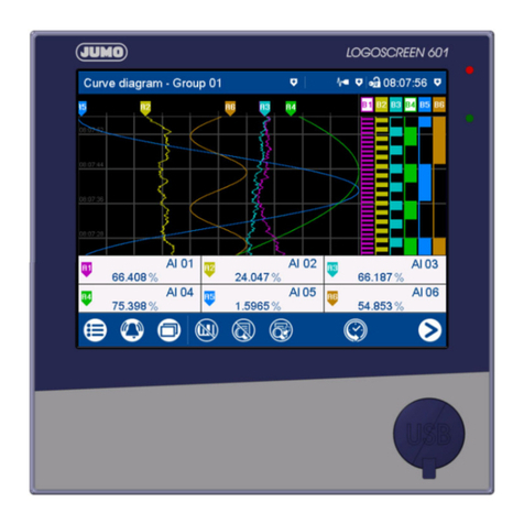
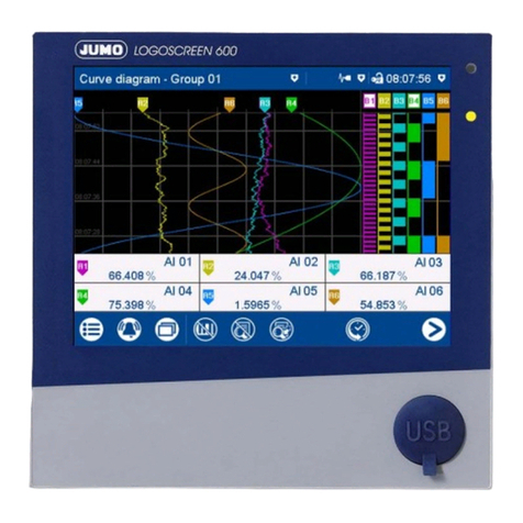
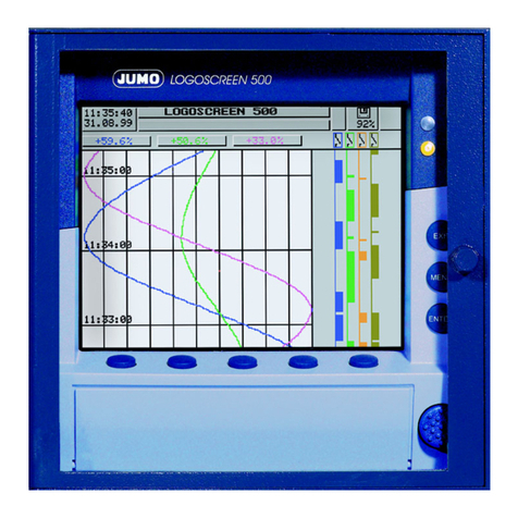
JUMO LOGOSCREEN Series User manual

Paperless Recorder
for secure acquisition
of FDA-compliant
measurement data
B 95.5011.4
Installation Instructions
11.04/00415650
es

Menu structure of the paperless recorder

Contents
1 Introduction 5
1.1 Preface .......................................................................................................... 5
1.2 Arrangement of the documentation ........................................................... 6
1.3 Typographical conventions ......................................................................... 8
2 Identifying the instrument version 9
2.1 Nameplate ..................................................................................................... 9
2.2 Type designation ........................................................................................ 10
2.3 Standard accessories ................................................................................ 11
2.4 Accessories ................................................................................................ 11
3 Installation 13
3.1 Location and climatic conditions .............................................................. 13
3.2 Mounting in position .................................................................................. 13
4 Electrical connection 15
4.1 Installation notes ........................................................................................ 15
4.2 Procedure .................................................................................................... 16
4.3 Connection diagram .................................................................................. 17
5 Function check 21
6 Device replacement / software update 23
7 Technical data 25
8Index 29

Contents

5
1 Introduction
1.1 Preface
Please read these Installation Instructions before commissioning the instru-
ment. Keep the instructions in a place that is accessible to all users at all
times.
Please assist us to improve these installation instructions, where necessary.
Your suggestions will be appreciated.
HIf any problems should occur during commissioning, please do not
carry out any manipulations on the unit, as this could endanger
your rights under the instrument warranty!
Please contact the nearest subsidiary or the head office in such a
case.
EWhen returning modules, assemblies and components, the regula-
tions of EN 61340-5-1 and EN 61340-5-2 “Protection of electronic
devices from electrostatic phenomena” must be observed. Use
only the appropriate ESD packaging for transport.
Please note that we cannot accept any liability for damage caused
by ESD (electrostatic discharge).
B

1 Introduction
6
1.2 Arrangement of the documentation
The documentation for this instrument is addressed to the equipment manu-
facturer (OEM) and users with appropriate technical expertise. It consists of
the following parts:
Sales documentation in PDF file format
White Paper The White Paper presents the company’s position with regard to the legislation
“21 CFR Part 11” of the American health authority FDA (Food and Drug Ad-
ministration). With each section of the regulatory text, the user is given infor-
mation on the fulfillment of the requirements.
Product
description The product description illustrates the safety and operating concepts behind
the system, and the results that can be achieved by JUMO in the course of the
validation of an installation. It is intended to serve as an introduction to the
system, and not as a formal technical documentation.
Instrument documentation in printed form
B 95.5011.1 Operating Instructions
The operating instructions are an extract from the operating manual. They co-
ver the basic operation of the paperless recorder.
B 95.5011.4 Installation Instructions
The installation instructions describe the installation of the paperless recorder
and the connection of the supply and signal cables. The instructions also con-
tain a list of the technical data.
Instrument documentation in PDF file format
The “Instrument documentation in PDF file format” is on the CD that is inclu-
ded in the delivery.
B 95.5011.0 Operating Manual
It contains information about commissioning, operation and parameter setting
on the instrument as well as through the PC setup program (option).
B 95.5011.1 Operating Instructions
The operating instructions are an extract from the operating manual. They co-
ver the basic operation of the paperless recorder.

7
1 Introduction
B 95.5011.2.0 Interface description (serial interfaces)
This provides information on the communication (RS232; RS422/RS485) with
supervisory systems.
Interface description (Ethernet interface)
This provides information on the connection of a paperless recorder to a com-
pany-internal network. The description is incorporated in the B 95.5011.2.0
B 95.5011.2.1 Interface description (LON interface)
This provides information on the connection and use of modules of the “JUMO
mTRON automation system”.
B 95.5011.2.3 Interface description (PROFIBUS-DP interface)
This provides information on the connection of a paperless recorder to a
PROFIBUS-DP system.
B 95.5011.4 Installation instructions
The installation instructions describe the installation of the paperless recorder
and the connection of the supply and signal cables. They also contain a list of
the technical data.
T 95.5011 Data sheet
The data sheet contains general information, the order details and the techni-
cal data.
HAll documents are available on the Internet for downloading at
www.jumo.net

1 Introduction
8
1.3 Typographical conventions
Warning signs
The signs for Danger and Caution are used in this manual under the following
conditions:
V
Danger
This symbol is used where there may be danger to personnel if the instruc-
tions are disregarded or not followed accurately!
ACaution
This symbol is used where there may be damage to equipment or data if the
instructions are disregarded or not followed accurately!
E
Caution
This symbol is used where special precautions must be taken when handling
electrostatically sensitive components.
Note signs
HNote
This symbol is used to draw your special attention to a remark.
vReference
This sign refers to further information in other manuals, chapters or sections.
abc1Footnote
Footnotes are comments that refer to specific parts of the text. Footnotes
consist of two parts: a marking in the text and the footnote text.
The marking in the text is arranged as continuous superscript numbers.
h
Action
This sign marks the description of a required action.
The individual steps are indicated by this asterisk, e. g.
hPress the hkey
hConfirm with E

9
2 Identifying the instrument version
2.1 Nameplate
Identification
Position The nameplate is affixed to the paperless recorder.
Contents It contains important information such as:
Typ Please compare the type that was supplied with your order details. You can
identify the type by referring to Chapter 2.2 “Type designation”.
VARTN The sales number unambiguously designates the article in the catalog. It is
used for communication between the customer and the sales department.
F-Nr The production number indicates the production date (year/week). The figures
concerned are in position 12, 13, 14, 15.
Example:
F-Nr 0022969000003130006
This shows that the paperless recorder was manufactured in 2003, week 13.
Repeat order for a recorder in the identical version
When placing a repeat order for a paperless recorder of the same type, it is ne-
cessary to state “Typ”, “VARTN” and “F-Nr.” This is the only way an instrument
of the same type can be produced.
Description Designation on
nameplate Example
Instrument type Typ 955011/10-888,000-51-
0032-0032-23,020
Sales number VARTN 95/00342163
Production number F-Nr 0022969000003130006
Supply voltage AC 110 … 240V
+10/-15%, 48…63Hz

2 Identifying the instrument version
10
2.2 Type designation
Paperless recorder for secure acquisition of FDA-compliant meas. data
(1) Basic version
955011/00 paperless recorder, no analog inputs
955011/01 paperless recorder, no analog inputs, incl. PC
software package and interface cable/adapter
955011/10 paperless recorder with 6 analog inputs
955011/20 paperless recorder with 6 analog inputs, incl. PC
software package and interface cable/adapter
955011/11 paperless recorder with 12 analog inputs
955011/21 paperless recorder with 12 analog inputs incl. PC
software package and interface cable/adapter
(2) Inputs 1 — 6 (configurable)
x x 000 not assigned
x x x x 888 factory-set
(3) Inputs 7 — 12 (configurable)
x x x x 000 not assigned
x x 888 factory-set
(4) Interface
x x x x x x 51 RS232C (standard)
x x x x x x 54 RS422/485
x x x x x x 66 RS232C and LON
x x x x x x 67 RS422/485 and LON
x x x x x x 68 RS232C and PROFIBUS-DP
x x x x x x 69 RS422/485 and PROFIBUS-DP
(5) Internal memory
x x x x x x 0032 32MB backup memory
x x x x x x 0064 64MB backup memory
x x x x x x 0128 128MB backup memory
(6) External memory
x x x x x x 0000 no external memory
x x x x x x 0032 32MB CompactFlash memory card
x x x x x x 0064 64MB CompactFlash memory card
x x x x x x 0128 128MB CompactFlash memory card
(7) Supply
x x x x x x 23 110 — 240V AC +10/-15%, 48 — 63Hz
xxxxxx 25 20—30VAC/DC,48—63Hz
(8) Extra codes
x x x x x x 008 Ethernet connection
x x x x x x 020 lithium battery for memory buffering (ex-factory)
xxxxxx 021 storage capacitor (instead of extra code 020)
x x x x x x 061 UL approval
x x x x x x 258 7 logic inputs, 1 open-collector output,
4 relay outputs, voltage output 24V DC 50mA
xxxxxx 350 universal carrying case TG-352
x x x x x x 444 stainless steel front with membrane keys
(1) (2) (3) (4) (5) (6) (7) (8)
Order code - , - - - - / ,...
Order example 955011/10 - 888 , 000 - 51 - 0032 - 0032 - 23 / 0201
1. List extra codes in sequence, separated by commas.
2. The UL approval (061) only applies to the panel-mounting unit.

11
2 Identifying the instrument version
2.3 Standard accessories
- 1 Installation Instructions B 95.5011.4
- 1 Operating Instructions B 95.5011.1
- 2 mounting brackets
- 4 cable-tie with foot (can be released)
for strain relief of the sensor connection cables
- 1 CD with additional documentation
(see Chapter 1.2 “Arrangement of the documentation”)
2.4 Accessories
- PC software package consisting of:
setup program,
PC evaluation software (PCA3000),
PCA communications software (PCC),
PC Security Manager software (PCS) and
PC Audit Trail Manager software (PCAT).
- PC interface cable with TTL/RS232 converter and adapter,
for setup program, Sales No. 95/00350260

2 Identifying the instrument version
12

13
3 Installation
3.1 Location and climatic conditions
The location should be as free as possible from shock and vibration. Stray
electromagnetic fields from motors, transformers etc. should be avoided.
The ambient temperature at the location can be 0 to +45°C, at a relative hu-
midity of ≤75%, no condensation.
vChapter 4.1 “Installation notes”
3.2 Mounting in position
Outline
drawings

3 Installation
14
Fitting into
the panel
Fitting in
position hInsert the paperless recorder from the front into the panel cut-out.
hFrom the back of the panel, hook the two mounting brackets into the
recesses on the sides of the housing. The flat sides of the brackets must be
against the housing.
hPlace the mounting brackets against the rear of the panel and tighten
them evenly.
Panel
min. 200

15
4 Electrical connection
4.1 Installation notes
kThe choice of the cable, the installation and the electrical connection
must conform to the requirements of VDE 0100 “Regulations on the In-
stallation of Power Circuits with nominal voltages below 1000V”, or the
appropriate local regulations.
kWork inside the instrument must only be carried out to the extent de-
scribed and, like the electrical connection, only by qualified personnel.
kIf contact with live parts is possible while working on the instrument, it
must be isolated from the supply on both poles.
kThe electromagnetic compatibility (EMC) conforms to the standards and
regulations listed under Technical Data.
vChapter 7 “Technical data”
kRun the input, output and supply cables separately, and not parallel to
one another.
kAll input and output cables without connection to the supply network
must be arranged as twisted and screened cables. Earth the screen on
the instrument side to the earth potential.
kEarth the instrument at the PE terminal to the protective conductor. This
cable should have the same cross-section as the supply cable. Earthing
cables should be run in a star layout to a common earthing point which is
connected to the protective conductor of the supply. Do not loop the
earthing cable, i.e. do not run it from one instrument to another.
kDo not connect any additional loads to the supply terminals of the instru-
ment.
kThe instrument is not suitable for use in hazardous areas.
kInductive loads close to the instrument, such as contactors or solenoid
valves, should have RC modules fitted for interference suppression.
kThe supply to the instrument must be provided with additional fusing.
Depending on the supply voltage, the following fuse values apply:
20 — 30V AC/DC, 48 — 63Hz : fuse 2A slow
110 — 240V AC +10/-15%, 48 — 63Hz : fuse 1A slow
A type-G miniature cartridge fuse marked F1 is built into the instrument
itself:
20 — 30V AC/DC, 48 — 63Hz : fuse 1.6A slow
110 — 240V AC +10/-15%, 48 — 63Hz : fuse 0.63A slow

17
4 Electrical connection
4.3 Connection diagram
Back panel Rear view with pluggable screw terminals
Cover for
back panel
VThe electrical connection must only be carried out
by qualified personnel.
(L-)
(L+)
Hole for lead sealing
Holes provided for the
cable-ties supplied,
for strain relief of the
connection cables

4 Electrical connection
18
Terminal assignment
Connector
Connection diagram
Supply Supply voltage
as per data sheet
L1(L+)
N (L-)
PE
Analog
inputs Thermocouple 1 to 12
Resistance thermometer
in 2-wire circuit
1 to 12
Resistance thermometer
in 3-wire circuit
1 to 12
Resistance thermometer
in 4-wire circuit
1 to 12
Resistance transmitter 1 to 12
Potentiometer in 2-wire circuit 1 to 12
Potentiometer in 3-wire circuit 1 to 12
Potentiometer in 4-wire circuit 1 to 12
Voltage input ≤ 200mV 1 to 12
Voltage input > 200mV 1 to 12
Current input 1 to 12
Interfaces RS232C 9-pole SUB-D socket
2 RxD receive data
3 TxD transmit data
5 GND ground
20
RL
RAR=R
AL
21 345
21 345
21 345
RL
RAR=R
AL
21 345
21 345
21 345
2
1
3
4
5
6
7
8
9

19
4 Electrical connection
Interfaces RS422 9-pole SUB-D socket
(extra code)
3 TxD+ transmit data +
4 RxD+receive data +
5 GND ground
8 TxD- transmit data -
9 RxD- receive data -
20
RS485 9-pole SUB-D socket
(extra code)
3 TxD+/RxD+ transmit/receive data +
5 GND ground
8 TxD-/RxD- transmit/receive data -
20
LON 9-pole SUB-D socket
(extra code)
3Net_A
9Net_B
21
PROFIBUS-DP 9-pole SUB-D socket
(extra code)
3 RxD/TxD-P B-cable
receive/transmit data-Plus
5 DGND data transmission potential
6 VP supply voltage-Plus
8 RxD/TxD-N A-cable
receive/transmit data-N
21
Ethernet RJ45 socket
(extra code)
1 TX+ transmit data +
2 TX- transmit data -
3 RX+ receive data +
6 RX- receive data -
22
Setup interface
The recorder also has a setup interface
on the front panel (wired in parallel).
Do not use both at the same time.
23
Relay
outputs Relay K1
(changeover, 3A, 230V AC)1
30
Relay K2 to K5
(make/break contact, 3A, 230V AC)1
(extra code)
31
1. with resistive load.
SELV circuits and supply circuits must not be combined.
Terminal assignment
Connector
Connection diagram
2
1
3
4
5
6
7
8
9
2
1
3
4
5
6
7
8
9
2
1
3
4
5
6
7
8
9
2
1
3
4
5
6
7
8
9
8
1
21 3
21
K2
43
K3
65
K4
87
K5

4 Electrical connection
20
Digital I/O Open-collector output
(25V max., 100mA max.)
(extra code)
3 ground
4 collector
32
Logic inputs, voltage-operated
(extra code)
LOW = -3 to +5V DC
HIGH = 12 to 30V DC
1 +24V/50mA
auxiliary supply not stabilized
2GND
5 Logic input 7
6 Logic input 6
7 Logic input 5
8 Logic input 4
9 Logic input 3
10 Logic input 2
11 Logic input 1
32
Example:
input 4 (terminal 8)
contact-operated
Input Terminal
111
210
39
48
57
66
75
Terminal assignment
Connector
Connection diagram
2345678910111
+–
Other manuals for LOGOSCREEN Series
1
Table of contents
Other JUMO Voice Recorder manuals

JUMO
JUMO LOGOSCREEN Series User manual

JUMO
JUMO LOGOSCREEN es User manual

JUMO
JUMO LOGOSCREEN nt User manual

JUMO
JUMO LOGOSCREEN 600 Reference guide

JUMO
JUMO Logoline 500 junior User manual

JUMO
JUMO LOGOSCREEN 601 User manual

JUMO
JUMO AQUIS touch S User manual

JUMO
JUMO LOGOSCREEN 500 User manual

JUMO
JUMO LOGOSCREEN cf User manual

JUMO
JUMO LOGOLINE 500d User manual