JUMO LOGOLINE 500d User manual

LOGOLINE 500d
Pen recorder with text printing
and LED dot matrix display
B 70.6021.0
Operating Manual
2011-01-19/00331468

Levels and key functions
Key functions
e- Chart fast forward when
recording is stopped
(in basic status)
- Aborting parameter input
(Exit)
- Level change backwards
S-Start/Stop recording
- Decimal place selection
during value input
- For text input:
rapid character selection
(jump to “ ”,“0”,“A”,“a”,
“°”, “²”,“À”,“à”)
F-Function key
for special function
(hold down at least 4sec)
factory setting:
scale printout
l,r- Cursor left/right
(select digit)
l+r- Deactivate/activate
display of status/error
messages
h,R- Select display:
- date and time
- channel measurements
- bargraph
- system states
- Parameter selection
- Channel selection
- Value selection
from value table
- Increment/decrement
current digit
h+R- Level change forwards
E- Initiate parameter input
- Enter input
- Acknowledge error
message
- Activate/ deactivate
static display
(in basic status)

Contents
1 About this Manual 6
1.1 Introduction .............................................................................................................. 6
1.2 Arrangement of the documentation ........................................................................ 7
1.3 Typographical conventions ...................................................................................... 8
1.3.1 Warnings ................................................................................................................... 8
1.3.2 Notes ........................................................................................................................ 8
1.3.3 Presentation .............................................................................................................. 9
2 Identifying the instrument version 10
2.1 Instrument description ............................................................................................ 10
2.2 Type designation .................................................................................................... 11
2.3 Accessories ............................................................................................................ 12
3 Installation 13
3.1 Location and climatic conditions ........................................................................... 13
3.2 Fitting in position .................................................................................................... 14
4 Electrical connection 15
4.1 Notes on installation ............................................................................................... 15
4.2 Connection diagram ............................................................................................... 16
5 Starting up 18
5.1 Display and controls ............................................................................................... 18
5.2 Opening and closing the door ............................................................................... 18
5.3 Marking the channel label ...................................................................................... 18
5.4 Fitting the fibre pens ............................................................................................... 19
6 Preparation 20
6.1 Operating modes and status .................................................................................. 20
6.2 Operating principle ................................................................................................. 22
7 Text printing 30
7.1 Printing priorities ..................................................................................................... 30
7.2 Printing modes ....................................................................................................... 33
7.3 Clock time ............................................................................................................... 35
7.4 Scaling .................................................................................................................... 36
7.5 Changing the chart speed ...................................................................................... 38
7.6 Recording start and end ......................................................................................... 40
7.7 External text, binary-linked text, relay texts ........................................................... 41
7.8 Incrementing the event counter ............................................................................. 43
7.9 Statistical report ...................................................................................................... 44
7.10 Print test .................................................................................................................. 45
7.11 Service print ............................................................................................................ 46

Contents
8 Programming 47
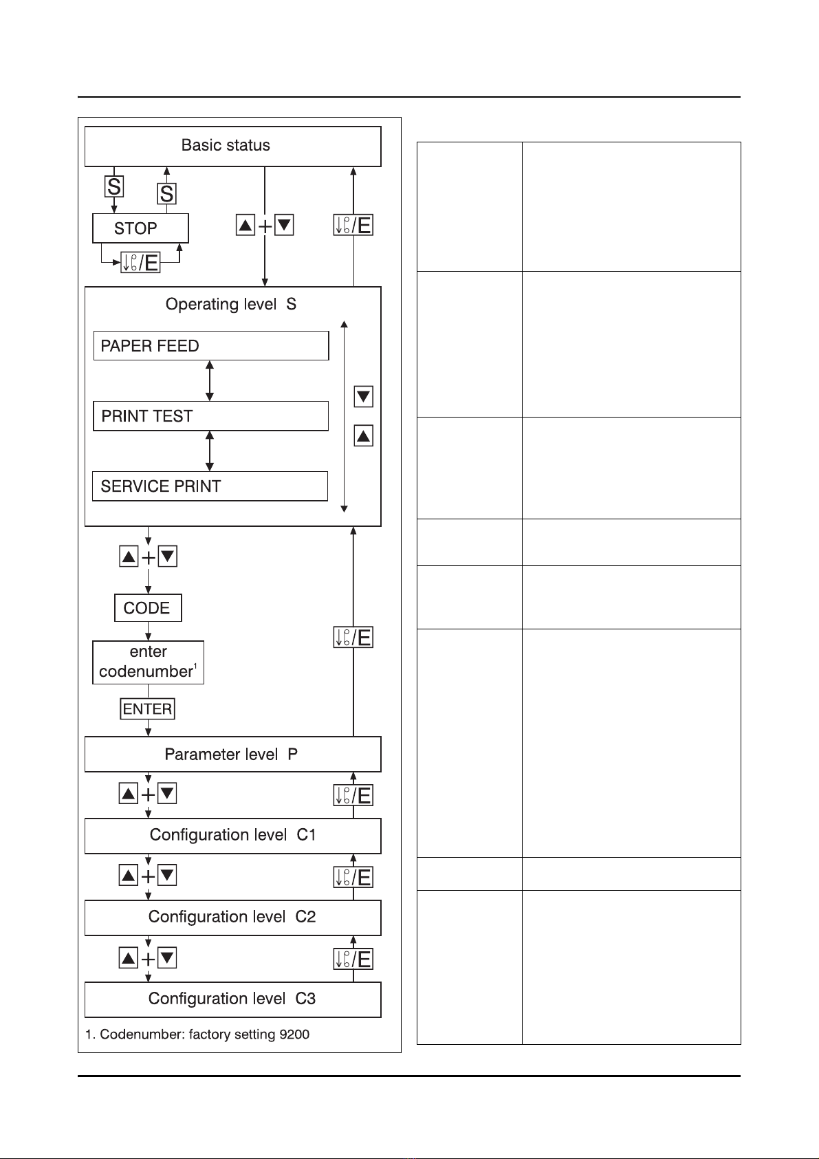
8.1 Basic status ............................................................................................................ 47
8.2 Operating level ....................................................................................................... 49
8.2.1 Chart speed ............................................................................................................ 50
8.2.2 Print test .................................................................................................................. 51
8.2.3 Service print ............................................................................................................ 52
8.2.4 Level inhibit and code request ............................................................................... 53
8.3 Parameter level ....................................................................................................... 55
8.3.1 Language ................................................................................................................ 56
8.3.2 Date and time ......................................................................................................... 57
8.3.3 Summer time .......................................................................................................... 58
8.3.4 Display brightness .................................................................................................. 59
8.3.5 Relay limits .............................................................................................................. 60
8.3.6 Display of time ....................................................................................................... 61
8.4 Configuration level 1 ............................................................................................... 62
8.4.1 Writing status .......................................................................................................... 63
8.4.2 Measurement/signal input .................................................................................... 64
8.4.3 Scaling .................................................................................................................... 73
8.4.4 Channel designation .............................................................................................. 74
8.4.5 Limit operation ........................................................................................................ 75
8.4.6 Plotarea (zoom) ...................................................................................................... 76
8.4.7 Presentation range (offset) ..................................................................................... 77
8.5 Configuration level 2 ............................................................................................... 78
8.5.1 Instrument designation ........................................................................................... 80
8.5.2 Speed programming mode .................................................................................... 81
8.5.3 Speed limit operation ............................................................................................. 82
8.5.4 Timed operation ..................................................................................................... 83
8.5.5 Scale printing .......................................................................................................... 84
8.5.6 Time printing ........................................................................................................... 85
8.5.7 Pen offset compensation ........................................................................................ 86
8.5.8 Statistical report ..................................................................................................... 87
8.5.9 Text at beginning .................................................................................................... 88
8.5.10 Text at end .............................................................................................................. 89
8.5.11 Presetting ................................................................................................................ 90
8.5.12 Codenumber .......................................................................................................... 91
8.6 Configuration level 3 ............................................................................................... 92
8.6.1 Relay output ........................................................................................................... 93
8.6.2 Maths and logics module ....................................................................................... 95
8.6.3 Interface .................................................................................................................. 96
8.6.4 External text ............................................................................................................ 98
8.6.5 Binary-linked external text ...................................................................................... 99
8.6.6 External stop ......................................................................................................... 100
8.6.7 External speed ...................................................................................................... 101
8.6.8 Event counter ....................................................................................................... 102
8.6.9 External scaling .................................................................................................... 103
8.6.10 External report ...................................................................................................... 104

Contents
9 Consumables 105
9.1 Summary of consumables ................................................................................... 105
9.2 Removing and replacing the chart cassette ........................................................ 106
9.2.1 Changing the roll chart ........................................................................................ 108
9.2.2 Changing the fanfold chart ................................................................................... 109
10 Extra Codes and accessories 110
10.1 Converting the chart cassette .............................................................................. 110
10.2 Extra Code 259 ..................................................................................................... 111
10.3 External relay module ER8 ................................................................................... 112
10.4 Setup program ..................................................................................................... 115
10.5 Maths and logics module ..................................................................................... 117
10.6 Interface (RS422/RS485) ..................................................................................... 118
11 Fault finding 119
11.1 What to do if... ...................................................................................................... 119
12 Appendix 121
12.1 Technical Data ...................................................................................................... 121
12.2 Error messages .................................................................................................... 125
12.3 Hardware fault ...................................................................................................... 127
12.4 Status messages .................................................................................................. 128
12.5 Character set ........................................................................................................ 129
12.6 Summary of the parameters ................................................................................. 130
13 Index 132

6
1 About this Manual
1.1 Introduction
Please read this Manual before
starting up the instrument. Keep the
Manual in a place which is at all
times accessible to all users.
Please assist us to improve this
Manual where necessary.
Your suggestions will be most wel-
come.
Phone
in Germany (0661) 6003-727
from abroad (+49) 661 6003-0
Fax
in Germany (0661) 6003-508
from abroad (+49) 661 6003-607
All necessary settings and, where
appropriate, alterations inside the
instrument are described in this
Operating Manual. However, if any
difficulties should arise during start-
up, please do not carry out any
manipulations. You could endanger
your rights under the instrument
warranty!
Please contact the nearest subsidi-
ary or the head office in such a
case.
E
When returning modules, assem-
blies or components, the regula-
tions of EN 61340-5-1 and 61340-5-
2 “Protection of electronic devices
from electrostatic phenomena”
must be observed. Use only the
appropriate ESD packaging for
transport.
Please note that we cannot accept
any liability for damage caused by
ESD.
ESD=electrostatic discharge

1 About this Manual
7
1.2 Arrangement of the
documentation
The documentation for this instrument con-
sists of the following parts:
Operating Manual B 70.6021.0
This Operating Manual is always supplied
with the instrument. It is addressed to the
OEM (original equipment manufacturer)
and to the user with appropriate technical
know-how.
In addition to installation and electrical con-
nection it contains all the information on in-
strument start-up, operation and parameter
setting.
Interface Description B 70.6001.2
This Operating Manual is supplied with the
instrument, if one the interfaces (RS422 or
RS485) has been ordered. It provides infor-
mation on communication with higher-level
(supervisory) systems.
Online help
The online help is part of the setup program.
It is a Windows1online help.
1. Microsoft und Windows are registered trade-
marks of the Microsoft Corporation
Section 10.4

1 About this Manual
8
1.3 Typographical conventions
1.3.1 Warnings The signs for Danger and Warning are
used in this Manual under the following con-
ditions:
VDanger This symbol is used when there may be
danger to personnel if the instruction is
disregarded or not followed accurately.
Warning This symbol is used when there may be
damage to equipment or data if the
instruction is disregarded or not followed
accurately.
EWarning This symbol is used where precautions
have to be observed during the handling of
components which may be damaged by
electrostatic discharges.
1.3.2 Notes
Note This symbol is used if your special atten-
tion is drawn to a remark.
Reference This symbol refers to additional information
in other handbooks or sections.
abc1Footnote Footnotes are notes which refer to certain
points in the text. Footnotes consist of 2
parts:
Markings in the text and the footnote text.
The markings in the text are arranged as
continuous raised numbers.

1 About this Manual
9
* Action This symbol indicates that an action is being
described.
The individual steps are indicated by this
symbol, e.g.:
* press key h
* enter with E
1.3.3 Presentation
h+EKeys Keys are shown as boxes. Both symbols
and text are possible. Where a key has mul-
tiple functions, the text shown is the one
corresponding to the actual fuctions dis-
cussed.
Program
manager Screen
texts Texts displayed in the setup program are
identified by italics.
Edit
instrument data... Menu items Menu items of the setup program which are
referred to in this Manual are shown in ital-
ics. Menu name, menu item and submenu
item are each separated by the symbol “”.

10
2 Identifying the instrument version
2.1 Instrument description
The pen recorder provides 1, 2 or 3 chan-
nels for recording; the channels are isolated
from each other by optocouplers. Channel 1
can be used to write text in addition to the
signal trace. All three channels are zeroed
using Hall sensors.
A 24-place 5x 5 LED dot matrix display is
available for signal indication and program-
ming. Operation is by eight keys on the in-
strument front and via a setup program us-
ing a PC. The configuration data are stored
permanently in EEPROM.
Input signals include resistance thermome-
ters, resistance transmitters, thermocouples,
standard current and voltage signals. The
necessary linearisation is performed auto-
matically. Eight logic inputs are available for
operating functions. An external relay mod-
ule ER8 for rail mounting supplements the
pen recorder by eight switching outputs.
A 2-wire transmitter can be operated from
an isolated supply. The watchdog monitors
the recorder operation and triggers a restart
in case of a fault. On a power failure the
real-time clock is supplied by a lithium bat-
tery or a storage capacitor.
A summary of all recorder parameters is
given in the Appendix (Section 12.6).

2 Identifying the instrument version
11
2.2 Type designation
The label is affixed to the housing. The in-
strument version can be identified from the
type designation.
The extra Codes are listed in sequence and
separated by a comma.
The voltage of the supply must agree with
the voltage shown on the label.
1. Please specify probe types and measurement
ranges in plain text.
2. This extra code is available in combination with
supply voltage 110—240V AC, not with low supply
voltage. UL approval is not available.
The protection type in the carrying case
corresponds to IP20, outside IP20D.
3. UL approval is not available.
4. Extra codes are listed in sequence and separated
by a comma.
(1) Basic version
706021 LOGOLINE 500d with 1 universal input and text output
706022 LOGOLINE 500d with 2 universal inputs and text output (via channel 1)
706023 LOGOLINE 500d with 3 universal inputs and text output (via channel 1)
(2) Inputs 1 — 3 (programmable)
xxx 8 factory-set
xxx 9 configuration to customer specification1
(3) Interface
xxx 00 notassigned
x x x 52 RS422, Jbus, Modbus
x x x 53 RS485, Jbus, Modbus
(4) Supply
x x x 22 20—53V AC/DC +0/-0% 48—63Hz
x x x 23 110—240V AC +10/-15% 48—63Hz
(5) Extra codes
x x x 020 lithium battery for RAM buffer (ex-factory)
x x x 021 storage capacitor for RAM buffer (instead of extra code 020)
x x x 259 8 logic inputs, interface for external relay module (ER8),
voltage output 24V 50mA DC
x x x 265 door with lock (IP54)
x x x 266 IP65 seal, wide fixing brackets
xxx 350 universal carrying case TG-352
xxx 351 housing with carrying handle3
(1) (2) (3) (4) (5)
Order code /--/
, ...4
Order example 706023 / 8 - 00 -23 /020

2 Identifying the instrument version
12
Standard accessories
- 1 Operating Manual B 70.6021.0
- 2 Mounting brackets
- 3 cable-tie with foot (can be released)
for tension relief of the sensor leads
connected
- 1 Fibre pen, disposable, for each channel
- 2 Chart rolls 16m long
or
1 Chart roll 32m long
(with Code r32)
or
1 Fanfold chart pack 16m long
(with Code fp)
2.3 Accessories
- PC interface with TTL/RS232 converter
- PC interface with USB/TTL converter
- Setup program
External relay module ER8
Section 10.4
Section 10.3

13
3 Installation
3.1 Location and climatic
conditions
The instrument location should as far as
possible be free from shock and vibration.
Stray electromagnetic fields, e.g. from mo-
tors, transformers etc., should be avoided
where possible.
The ambient temperature at the location
may be between –10 and+50 °C at a relative
humidity not exceeding 75 %, without con-
densation.
Corrosive air or fumes may interfere with the
function and life of the recorder.
Section 4.1
Section 12.1

3 Installation
14
3.2 Fitting in position
Side view
(dimension 26 increased to 27 when using
the IP65 seal)
Front view
Panel cut-out
* Insert the recorder from the front into
the panel cut-out.
* From the back of the panel, hook the
mounting brackets (1) into the cut-outs in
the sides of the housing. The flat bracket
faces must lie against the housing.
* Place the brackets against the rear of the
panel and tighten them evenly.
(1)
mm inch
22.5 0.89
30 1.2
36 1.42
60 2.4
100 3.94
108 4.25
110 4.33
120 4.72
136 5.35
138+1 5.43+0.04
144 5.67
227 8.94
16 m 53 ft
32 m 107 ft
1.5 mm20.0025 in2
2.5 mm20.004 in2

15
4 Electrical connection
4.1 Notes on installation
❏The choice of cable, the installation and
the electrical connection of the instru-
ment must conform to the requirements
of VDE 0100 “Regulations on the Instal-
lation of Power Circuits with nominal
voltages below 1000V” or the appropri-
ate local regulations.
❏Earth the instrument at terminal PE to
the earth conductor. This line should
have at least the same cross-section as
the supply lines. Earth lines should be
run in a star layout to a common earth
point which is connected to the earth
conductor of the supply. Do not loop the
earth connections, i.e. do not run them
from one instrument to another.
❏Work inside the instrument must only be
carried out to the extent described and,
like the electrical connection, only by
properly qualified personnel.
❏Do not connect any additional loads to
the supply terminals of the instrument.
❏If contact with live parts is possible when
working on the instrument, it has to be
isolated on both poles from the supply.
❏The instrument is not suitable for instal-
lation in hazardous areas.
❏Electromagnetic compatibility (EMC)
conforms to the standards and regula-
tions listed under Technical Data.
Section 12.1
❏Inductive loads in the neighbourhood of
the instrument, such as contactors or
solenoid valves, should be fitted with RC
modules for interference suppression.
❏Run input, output and supply lines sepa-
rately, and not parallel to each other.
❏The instrument must be provided with
external fusing and disconnection. De-
pending on the supply voltage, the fol-
lowing fuse values apply for the external
fusing:
20 — 53V AC/DC, 48 — 63Hz
fuse 5A slow
93 — 263V AC, 48 — 63Hz
fuse 5A slow
❏All input and output lines that are not
connected to the supply network must
be laid out as shielded and twisted
cables. The shielding must be grounded
to the earth potential on the instrument
side.

4 Electrical connection
16
4.2 Connection diagram
Rear view with screw-clamp
connectors
V
The electrical connection
must only be carried out
by properly qualified
personnel.
Terminals
Supply as on label N neutral
L1 line
PE potential earth
N(L-)
L1 (L+)
PE
Analogue inputs Input 1 Input 2 Input 3
Field Field Field
Voltage input
up to 170 mV
1. 2. 3.
Voltage input
above 170 mV
Current input
Thermocouple
Thermocouple with external
Pt 100 cold junction
recesses for cable-tie with foot for tension relief

4 Electrical connection
17
Analogue inputs Input 1 Input 2 Input 3
Resistance thermometer/
potentiometer in 2-wire circuit
Field Field Field
1. 2. 3.
*Rcomp=Rline
Resistance thermometer/
potentiometer in 3-wire circuit
Resistance thermometer/
potentiometer in 4-wire circuit
Resistance transmitter
with 3-wire connection
A = start
S = slider
E = end
Field
External relay module ER8 Communication with ex-
ternal relay module ER8
8.
Supply for external 2-wire
transmitter
24V ±5%, 45 mA
Logic operating inputs Contact operation
LOW = ROFF ≥100kΩ min.
HIGH = RON ≤ 50 Ωmax.Terminal 7=logic input 1
...
Terminal 14=logic input 8
Minimum pulse duration:
HIGH 500 msec
LOW 500 msec
Voltage operation
LOW = 0 — 5 V DC
(not activated)
HIGH = 20 — 35 V DC
(activated) Terminal 7=logic input 1
...
Terminal 14=logic input 8
Serial interface
RS422 or RS485
Communication with
higher-level systems 9.

18
5 Starting up
5.1 Display and controls
(1) 24-position 5x5 dot matrix
LED display
(2) fibre pen, channel 3, green
(3) fibre pen, channel 2, red
(4) fibre pen, channel 1, blue
(5) chart
(6) setup interface
(behind swing-up LED dot matrix
display)
(7) keys for operation and programming
(8) door
(9) housing to DIN 43700 for flush panel
mounting, galvanised steel
(10) channel marker label
5.2 Opening and closing the
door
Turn the knob to open or close the door.
5.3 Marking the channel label
Please mark the channel label (1) with the
measurement channel designation and the
corresponding range (plot area and offset
where appropriate).
(1)
(2)
(3)
(4)
(5)
(6)
(7)
(8)
(9)
(10)
SF
ENTER
/E
/E SFENTER
(1)

5 Starting up
19
5.4 Fitting the fibre pens
* Open the recorder door
* Stop recording
(e.g. press key S)
* Swing display upwards
* Slide the fibre pen into the holder up to
the stop
* Swing display down again until it clicks
home.

20
6 Preparation
6.1 Operating modes and status
Operating mode/status Description
Basic status Basic status of the recorder with signal acquisition and
processing.
The display shows, depending on setting:
- instrument designation, date and time
- one channel and its measurement as number
or bargraph
- or status/error messages.
The display can be altered during recording, using the
keys hand R.
If there is a status/error message, it is shown flashing at
regular intervals instead of the current display.
Stop
Stop by key Recording is stopped and continued using key S.
In the stop status the display flashes STOP.
Stop via external stop External stop can be operated through a signal at a
logic input on the back of the recorder. In the external
stop status the display flashes EXTERNAL STOP.
Chart speeds
Normal chart speed The chart is advanced at the speed programmed under
chart speed.
Section 8.2.1
Limit operation When input goes above/below the programmed limits,
the recorder switches to the chart speed programmed
under “limit feed”.
Section 8.4.5
Section 8.5.3
Section 10.4
External speed On a signal applied to a logic input at the back of the
recorder, it switches to the chart speed programmed
under “feed extern”.
Section 8.6.7
Section 10.4
Table of contents
Other JUMO Voice Recorder manuals

JUMO
JUMO LOGOSCREEN nt User manual

JUMO
JUMO LOGOSCREEN 500 User manual

JUMO
JUMO LOGOSCREEN es User manual

JUMO
JUMO LOGOSCREEN nt User manual

JUMO
JUMO AQUIS touch S User manual

JUMO
JUMO LOGOSCREEN 601 User manual

JUMO
JUMO LOGOSCREEN cf User manual

JUMO
JUMO Logoline 500 junior User manual

JUMO
JUMO LOGOSCREEN 600 Reference guide

JUMO
JUMO LOGOSCREEN Series User manual