ul. Zgorzelicka 34 , 97-200 Tomaszow Mazowiecki POLAND
JuNa PPHU Manufacturer
7
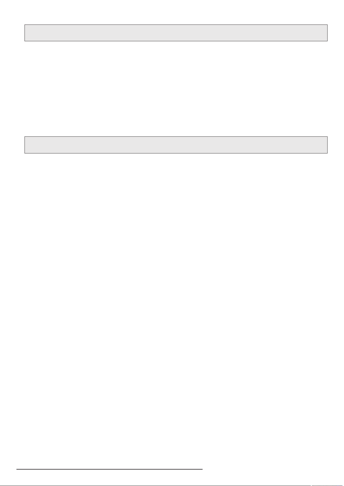
1. Turn the ignition and NTG Command system off
2. Take the NTG Command system out from middle panel
3. Disconnect QUADLOCK connector from NTG Command unit
4. Plug the K-SW102MR connector to QUADLOCK
5. Connect QUADLOCK connector to NTG Command unit
6. Connect K-SW102MR connector to JRDAB-03 module socket
7. Connect W-ZAZ101a connector to JRDAB-03 module socket
8. Connect FAKRA connector to JRDAB-03 module antena socket
9. Connect supply wires from W-ZS101a to QUADLOCK (Pic.5)
10. Plug the header from set to socket in fiber optic cable K-SW102MR
11. lnstall Command NTG unit in middle panel
12. Turn the ignition on and start the unit in car
13. Run module adaptation process to system
1
2
33
4
5
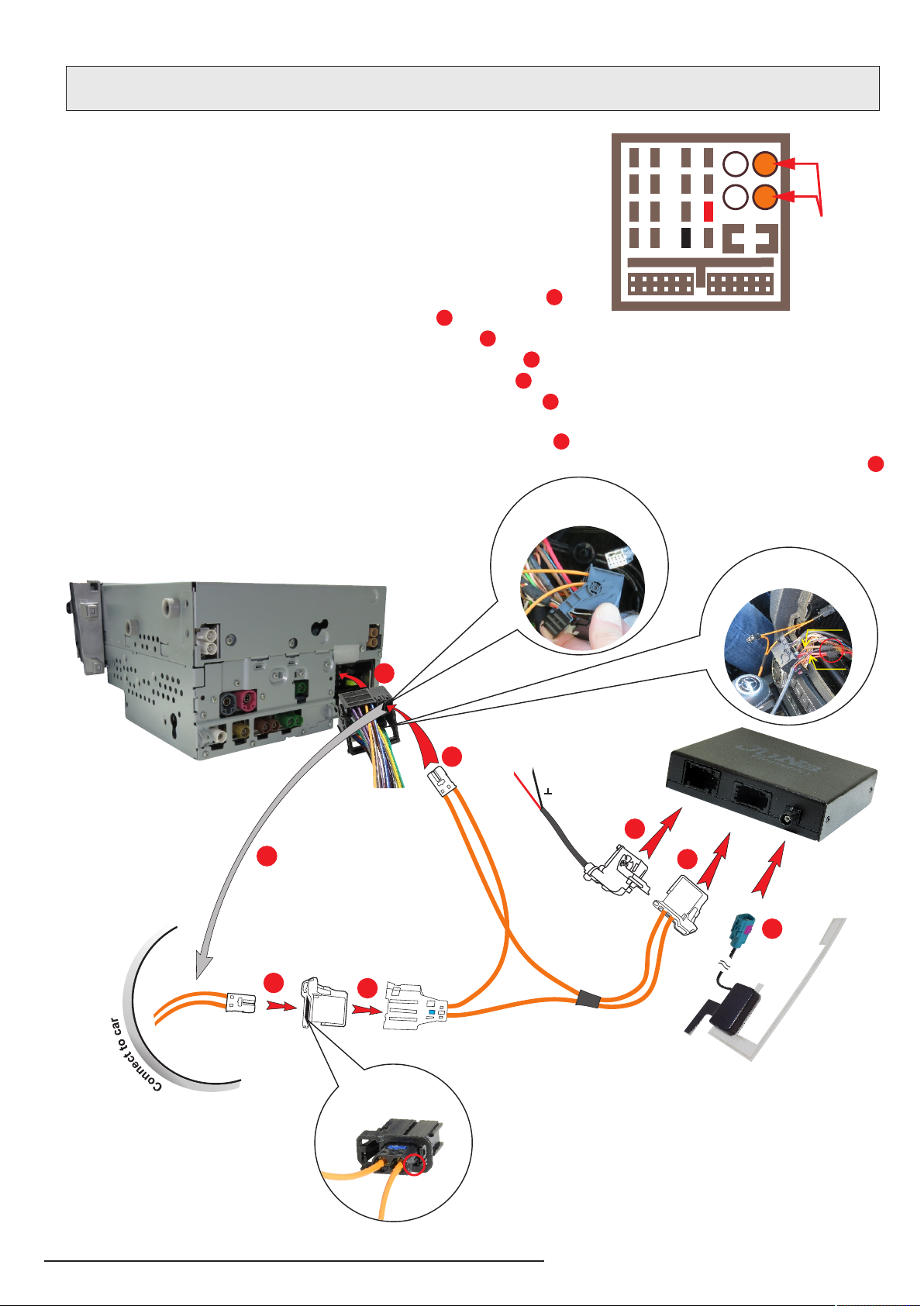
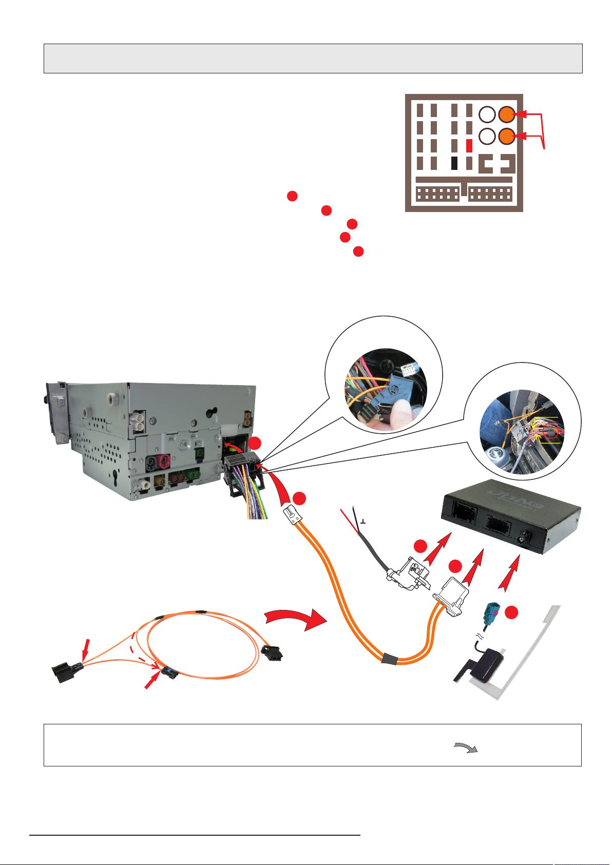
6. CONNECTION DIAGRAM - CASE lI
Connection diagram of JRDAB-03 with multimedia unit Mercedes Benz NTG
for cars not equipped with modules connected to fiber optic bus MOST.
3
4
5
+12V GROUND
Pic.6
1
2
lnformation:
Detailed diagram of preparation fiber optic bundle MOST is on page 8.
A.
B.
In fiber optic bundle added to set:
1. Disconnect wire from fiber optic socket "A".
2. Disconnect wire from fiber optic plug "B".
3. Connect disassembled fiber optic wire "A" to connector "B".
x
x
+12V
Ground
Power connection
the JRDAB-03 module
Connection of the
connector
fiber in QUADLOCK
lnformation: We reccommend to connect
supply wires to QUADLOCK socket - pin 12 ground
and pin . The connection must be electrically 15 (+12V)
durable, preferably soldered and properly insulated.
We do not recommend crimp connections.
Pic.5
FUSE
1
4
5
8
9
12
13
16
2610 14
3711 15
Złącze
MOST