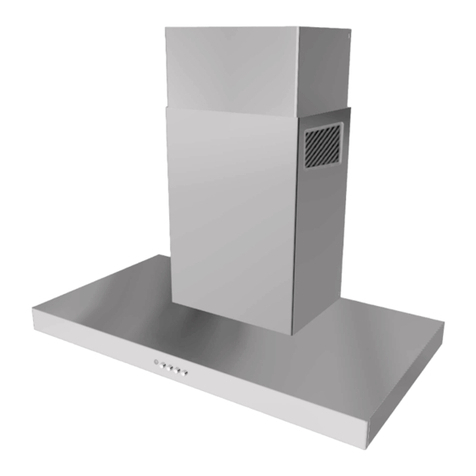
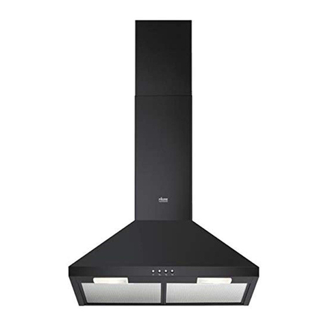
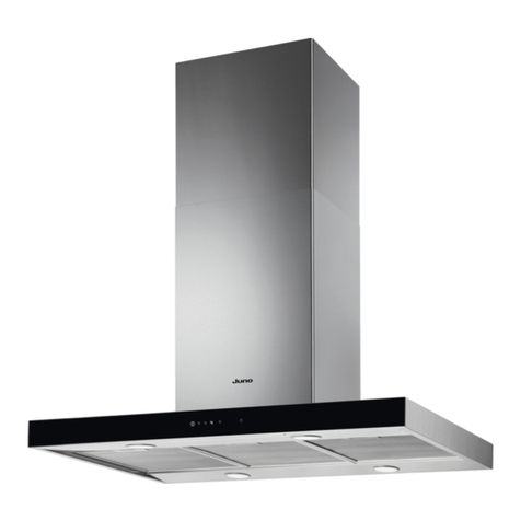
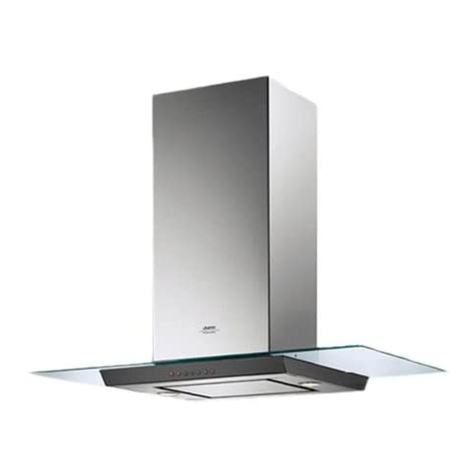
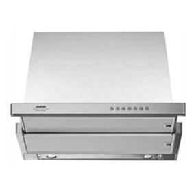
Hood Description
1) Motor speed button
2) Light button
3) Operating light
4) Exhaust grate
5) Work-light
Use
The hood may be used as follows:
— Exhausting version
— Recycling version
Exhausting version
The air is vented outdoors by a duct which
must be connected to the coupling ring A
(Fig. 1).
For JDK 9730 hood only:
Check if the internal shutters Sare opened
before using the hood (Fig. 11).
Choosing the exhausting pipe
The coupling ring Ahas a diameter of
120mm.
We suggest to use Ø 120 mm exhausting
pipe.
Using the multi-connector C, Ø100, Ø110
and Ø125 mm exhausting pipes can be
used.
Ø 120 mm exhausting pipe: the multi-
connector has not to be fitted.
Ø 125 mm exhausting pipe: insert the
multi-connector on the coupling ring and
remove, using a proper tool, the upper
unused Ø 100 and Ø 110 mm rings of the
multi-connector.
Ø 110 mm exhausting pipe: same
procedure,butremovingtheØ100mmring
only.
Ø 100 mm exhausting pipe: apply the
multi-connector on the coupling ring.
Recycling version
Theairisfilteredthroughacarbonfilterand
recirculatedintotheroomthroughthegrating
on the lower chimney part.
Thisversionisusedwhenthereisnoexhaust
duct for venting outdoors or when it is
impossible to install one.
Touse the hood in this version,proceed as
follows:
— If no carbon filter is supplied with the
hood, ask the technical assistance
service or the manufacturing company
for one and specify the hood model.
— Dismount the metal grease filters
— Toinstallthecarbonfilter,fititintheseat
at the back and fasten it at the front with
the two hooks B(Fig. 2).
— Re-fit the metal grease filters.
For JDK 9730 hood only:
Attention!ClosetheshuttersSbeforeusing
the hood in this version.
Installation
When installed, the hood must be not less
than 65 cm. above electric burners or 75
cm. above gas or mixed-fuel burners.
(h,Fig.3).
Warning!
— If the hood is run at the same time as a
burner or fireplace that depend on
ambient air (for example gas, Diesel,
coal or wood heaters, water heaters,
etc.)becareful,becausethehood,when
itexhausts the air, removes the ambient
airrequired by the burnerorfireplacefor
combustion.
— For secure operation and to prevent
dischargedgasfromcomingbackin,the
vacuum must not exceed 0,04 mbr.
Thismaybedone bymaking surethe air
inlet into the room passes through non-
closing openings such as air recycling
wallboxes,doors,windowsorwithother
technical measures.
—No food must be cooked flambé
underneath the hood.
The use of an unprotected flame is
dangerousforthefiltersandcouldcause
fires.
Therefore, never use an open flame
underthehood.Whenfryingfoods,never
leavethepanalonebecausethecooking
oil could flare up.
— The hood must not be connected to fuel
exhaust flues (boilers, heating systems,
water heaters, etc.).
— Please, keep to the provisions of official
directivesregardingthequestionoffume
discharge.
— The manufacturers refuse to accept any
responsibility for damage to the hood or
its catching on fire because of failure to
observe the above instructions.
Suggestions for the installation and
use of the hood
— The horizontal sections of the pipe must
beslanted slightly upwards (about10%)
toensureaneasyflowoftheairoutwards.
— The best performance of the unit is
obtained in the external exhaust model
(suction), therefore in the limits of the
possibilities it is advised to use the
external exhaust (suction) type.
— Thebestperformancesareobtainedwith
short pipes (max. 4 m) and with few
curves.
Electric connection
Before completing any connection, make
sure the house voltage corresponds with
the voltage indicated on the label affixed
inside the hood.
The hood is supplied with a standard plug;
connect it to a correspondingly standard
socket. In the case is intended to connect
the appliance permanently to the mains
after having removed the plug supplied,
mustbefitted atwo-poleswitchconforming
to regulations with an opening distance
between contacts of not less than 3mm.
The manufacturers are not liable for any
problems caused by the user’s failure to
observe the above instructions.
Fastening the hood to the wall
(Fig. 4)
— Position the template in the correct
position and make two 8mm diameter
holes and two 12mm diameter holes.
—Fitthetwo8mmdiameterplugsinthetop
holes.
— Fasten the two hooks Cin the bottom
holes.
— Hang the hood on the hooks and level it
with the screws D.
— Secure it in place with the two 5x45 mm
screws and 5-20 mm diameter washers
inthetopholes.Thescrewsandwashers
are standard equipment.
Installing the duct for exhausting
version (Fig. 5-6)
— FastenthetopsupportEtothewallclose
to the ceiling on the perpendicular of the
bottom connections. To do use the two
8mmdiameterscrewsandplugssupplied
as standard equipment.
Insert the plastic mould Pon the duct.
— Take the measure between the ceiling
and the hood top, and adjust the duct to
this height. Fasten it with the screws
— Insertthe ductwith theslots downwards
andfasten it withthetwo topscrewsand
the two bottom screws G.
Installing the duct for recycling
version
Perform the same operations described in
the preceding paragraph. With screws
supplied, fasten the air conveyor Minside
the duct (Fig. 9).
Fastening of shelves (optional)
(Fig. 7)
FastenthefoursidesupportsItotheadjacent
cabinetsandplacetheshelfonthesupports.
Operation
The hoods JDK 8730 and JDK 9730 are
provided with a motor with several speeds.
For the best performance, we recommend
14 15
GB
