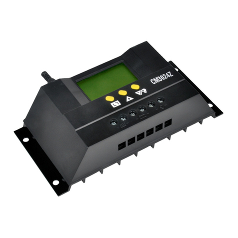
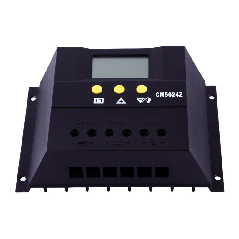
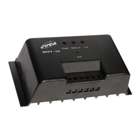
Juta SR1012 User manual

SR User’s Manual For Solar Charge Controller
I. Functions and Features
1. Series PWM charging control makes sure the controllers staying cool when
charging stopped.
2. The controller use a MCU as the controlling core, so charging control process is
more intelligent, and charge control voltage more accurate.
3. 3-stage charging control( Bulk, Absorption, Float), to full-charged battery faster.
4. 4-stage LED indicator which shows the battery’s SOC and charging stage.
5. 2 kinds of settable load working mode: Normal and Automatic light mode. the
controller will power on the load after darkness and will power off the load after
sunrise.
6. 2pcs of 5V USB power output ports.
7. 1 buttons to control the load switching and load mode switching.
8. The controller uses low conduction resistance of MOSFET as the charge and
discharge control device, utilization of solar panel would be more higher, charging
and discharging loss would be more less.
9. All sorts of perfect protect function: reverse-connect protection for battery,
reverse-connect protection for solar panel, prevent backflow function, low-voltage
protect, over-voltage protect, over-load protect.
II. Connection
1
2
3
4 8
5
6
7
Solar panel input terminals
Batter y input terminals
Load output terminals
Batter y SOC indicator
Installing hole
Load status indicator
USB power port
Load control button
1 2 3
5
7
4 6
8
100%
75%
50%
25%
N o rma l
Auto
O N O FF

III. LED Indicator Instruction
Battery’s Indicator
25%
50%
75%
100%
Meaning
●
Not flashing: remaining capacity of battery is between
0%~25%.
25% LED:≥12.4V,ON ≤10.7V slow flashing.
●
●
Not flashing: remaining capacity of battery is between
25%~50%.
50% LED:≥12.9V,ON ≤11.6V OFF.
●
●
●
Not flashing: remaining capacity of battery is between
50%~75%.
75% LED:≥13.4V,ON ≤12.0V OFF.
●
●
●
●
Not flashing: remaining capacity of battery is between
75%~100%.
100% LED:≥13.7V,ON ≤12.3V OFF.
●→●● → ●●●
←●●●●
Water lights, bulk charging stage, the controller charging
the battery with the maximum current that which solar
panels could provide.
●
●
●
¤
100% battery indicator continue to slow flashing,
Absorption charging stage, the controller uses PWM
mode to adjust the charging current to make the battery’s
voltage maintain the value of the absorption charge
voltage.
●
●
●
●←
¤
100% battery indicator slow flash 5s and then continue
5s, Float charging stage, the controller uses PWM mode
to adjust the charging current to make the battery’s
voltage maintain the value of the float charge voltage, to
supplement the battery’s discharge.
¤
25% battery indicator slow flash, battery’s voltage below
the low voltage protection point, the load have been
powered off. When the voltage returns to the low voltage
reconnection, the power returns supply automatically.
All battery’s SOC indicator flash quickly, battery’s
voltage over the over-voltage protection point, the load
have been powered off. When the voltage drops to the
over-voltage recovery point and it remains 5S, the
controller automatically recover to load supply.
¤
¤
25%,50% battery’s indicator flash slowly synchronous
for 6s, the controller detect the solar panel
disconnect.(The voltage of solar panels lower than 5V).
¤
¤
75%,100% battery’s indicator flash slowly synchronous
for 6s, the controller detect that the solar panel have been
connected.(The voltage of solar panels more than 6V).
●-on,¤-flash slow, -flash fast.

Load Mode Indicator
Normal
Auto
Meaning
●
The LED indicator is on, load control is in normal
mode, load is in normal power supply condition.
Flashing fastly, load control is in normal mode. Load
over current has occurred.the load have been powered
off automatically. You can manually unlock the
protection or wait the controller automatically unlock at
dusk.
¤
Flashing slowly, load control is in normal mode, load
have been powered off manually. And at this condition,
the controller wouldn’t be power on the load
automatically.
●
The LED indicator is on, the load is in light control
mode and the load is in normal power supply condition.
Flashing fastly, load control is in light control mode.
Load over current has occurred. the load have been
powered off automatically. You can manually unlock
the protection or wait the controller automatically
unlock at dusk.
¤
Low-voltage protection of battery or over-voltage
protection of battery,or load control is in light control
mode and now is daytime,or powered off manually in
light control mode.
●-on,¤-slow flashing, -Quick flashing.
IV. Instructions For Use
1.Battery Charging Control
The Charging process contain three stages: Bulk, Absorption, Float. On Bulk stage,
controller charge the battery with max current from solar panels; on Absorption stage,
controller will adjust the Duty Cycle of current to remain the battery voltage at
charging voltage point for 2H ,so that charge the battery full faster. Controller will
entry this stage only when the battery voltage stays lower than 12.6V for 5mins. If the
battery voltage does not satisfy this condition, the controller will directly enter the
float Stage. On Float Stage, controller will adjust the Duty Cycle of current to remain
battery voltage at Float charging point to supply the consumption of battery.
2.Normal Mode
Normal indicator is on or flickering ,means the load is in normal control mode,so
that the load do not in the the control of lighting.
In this mode, the load will be powered off only when battery low voltage,battery
over-voltage or over-load happened.
3.Lighting Control Mode
Auto indicator is on or flickering ,means load in lighting control moder.In this
mode, the controller will power on the load after darkness and will power off the load
after sunrise.Press the button "load " to turn on or turn off the load by manually.The
Power supply state of the load will be changed if in the face of the turning on or
turning off the load event (such as dawn, battery low voltage, load current).

4.Short Press The Button
Turn on or turn off the load and unlock the protection of controller on any of the
two Load modes (Battery over-voltage protection could not been unlock).
5.Long Press The Button
After 5s, load control mode will switch between the two modes. Corresponding
mode indicator will be on.
V. Fault And Handling
Fault Phenomenon
Causes of Fault
Solutions
After system connection,
all the indicators are off
The polarity of battery
reversed
Checking whether the connection
of battery polarity is right.
Battery voltage is too
low
Replaced battery or connect the
negative of the battery with the
negative of solar panels directly,
then disconnect them after the
controller power on.
Four battery capacity
indicators flicker quickly,
you can’t turn on the load
manually
The battery voltage
exceeds the over voltage
protection point
Checking whether the battery
voltage level is correct Checking
whether the battery's capacity is
matched to the power of the solar
panel.Checking whether there is
bad condition about connecting
line between the controller and
battery.
After Connected the solar
panel, charging indicator is
off
Solar panel connection
reversed
Checking whether the connection
of the polarity of solar panels is
correct.
Solar panel voltage is
too low
Checking whether the voltage of
the solar panel is greater than the
battery voltage.
The load shut down
automatically
Load mode stayed in the
light control mode
Long press the button 5S to switch
the load mode to normal mode.
Battery low-voltage
protection
After full-charged, the controller
started automatically.
Over-load protection
Turn on the load manually after
reducing the load.
VI. Quality Assurance
1. Quality assurance should be carried out according to the following rules:
● The product is guaranteed of replacement, returning and repairing within 7 days
after sale.
● The product is guaranteed of replacement and repairing within 1 month after sale.
● The product is guaranteed of repairing within 12 months after sale.
2. If it is not possible to identify the using date of the controller, we would refer to the
ex-work date, and prescribe 18 months as the warranty period. We need to charge
beyond the warranty period. The controller can be repaired for life no matter when
and where you use it.
3. If the controller is damaged by the following causes, we need to charge even if it is

In the guarantee period:
● Do not operate according to the user's manual.
● Use the controller under the condition which is beyond the using standard and
technical requirements.
● Repair by yourself or reform by yourself.
● The inappropriate environmental condition which can cause the breakdown and
aging of the apparatus.
● Improper carrying or storage.
● Regarding to the service of replacement, returning and repairing, you need to retreat
the product to our company, and we decide whether to replace or repair after we make
clear who should be responsible.
4. We will not note if there is any change of this product.
VII. Technical Data
Model
1012
2012
3012
Rated Voltage
12V
12V
12V
Rated Current
10A
20A
30A
Voltage Drop
0.1V/0.05V
0.2V/0.1V
0.2V/0.1V
Solar Input
≤25V/≤170W
≤25V/≤340W
≤25V/≤510W
Self Consumption
≤16mA
Absorption Voltage
14.4V/2h
Float Voltage
13.8V
LVD Voltage
10.7V
LVR Voltage
12.6V
HVD Voltage
15.5V
HVR Voltage
15.0V
Voltage Tolerance
±0.2V
Charging Control
3step,PWM
Load Mode
Normal, Auto
Photo Detection
Voltage
Dusk:5V, Dawn:6V
Load Over Current
1.1 times the rated current 20S
USB Power Output
2 port ( When using a single interface,
the maximum output current 1A )
Cable Dimension
<6mm2, 10# AWG
<16mm2,7# AWG
Installation Hole
Φ4mm-159mm*56mm
Φ5mm-178mm*60mm
Working
Temperature
-20℃~50℃
Storage
Temperature
-30℃~70℃
Humidity
≤90%, no condensation
Dimension
169mm*90mm*39mm
188mm*90mm*39mm
Weight
210g
253g
290g
This manual suits for next models
2
Other Juta Controllers manuals
Popular Controllers manuals by other brands

Emerson
Emerson Fisher FIELDVUE DVC6000 HW2 instruction manual

Helios
Helios KWL 45 BEU Installation and operating instructions

Veris Industries
Veris Industries G Series installation guide

Induction Solutions
Induction Solutions NPC-2006 user manual

Tech Controllers
Tech Controllers EU-294v1 user manual

Milltronics
Milltronics Accumass BW100 instruction manual