JVC CamiFlex FG-CAM-F4/U User manual


Table of contents
1 INTRODUCTION ............................................................................... 4
1.1 CAUTION – SAFETY INSTRUCTIONS................................................................................4
1.2 SERVICES INFORMATION AND CONTACT..........................................................................
1.3 WASTE ELECTRICAL & ELECTRONIC EQUIPMENT (WEEE)...............................................
1.4 RESTRICTION OF HAZARDOUS SUBSTANCES (ROHS).......................................................
1. GUARANTIES...........................................................................................................
1.6 EMC AND SAFETY...................................................................................................
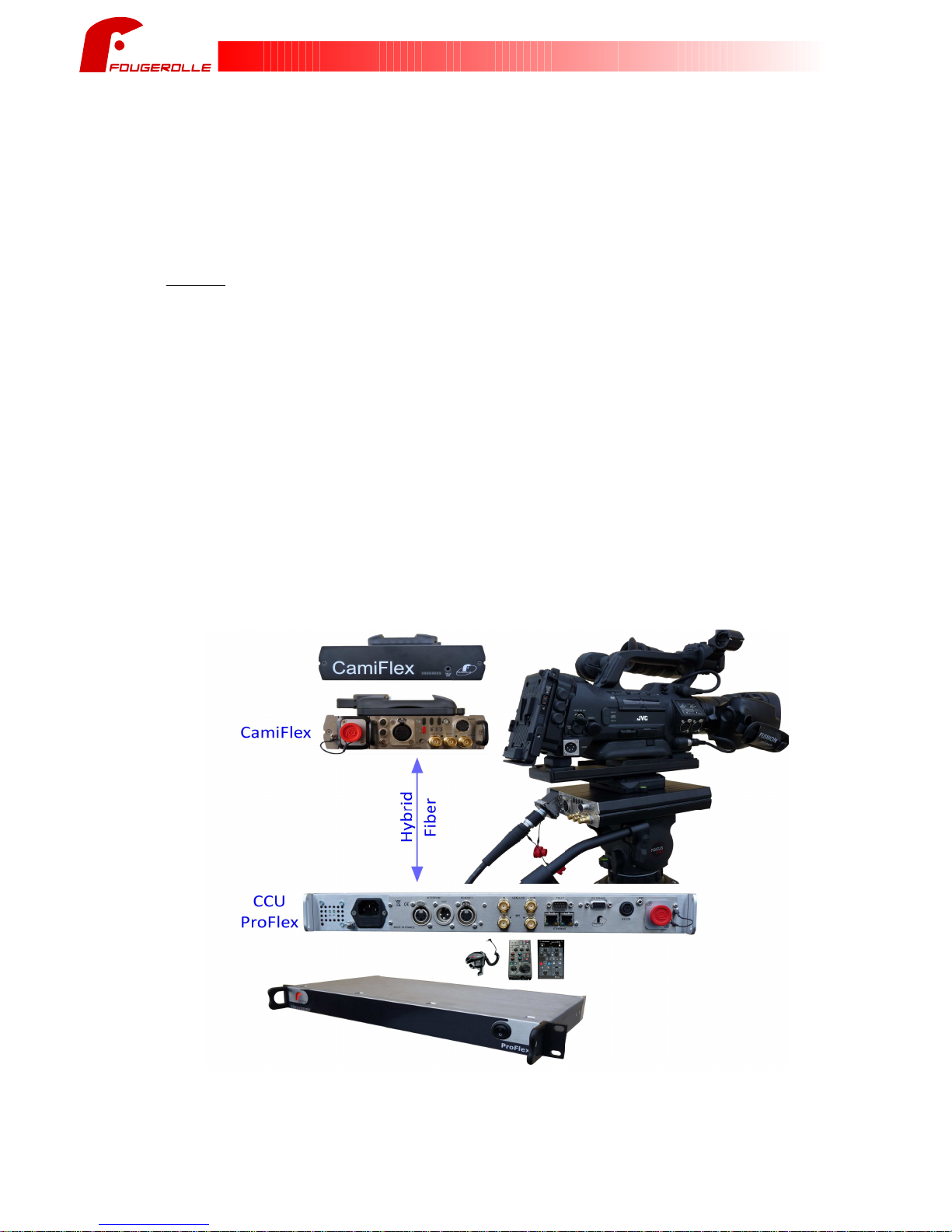
1.7 BASE UNIT – HEAD UNIT..........................................................................................6
1.8 CAMI-VL ADAPTER...................................................................................................7
2 INSTALLATION ................................................................................ 8
2.1 RACK MOUNT - BASE UNIT.........................................................................................8
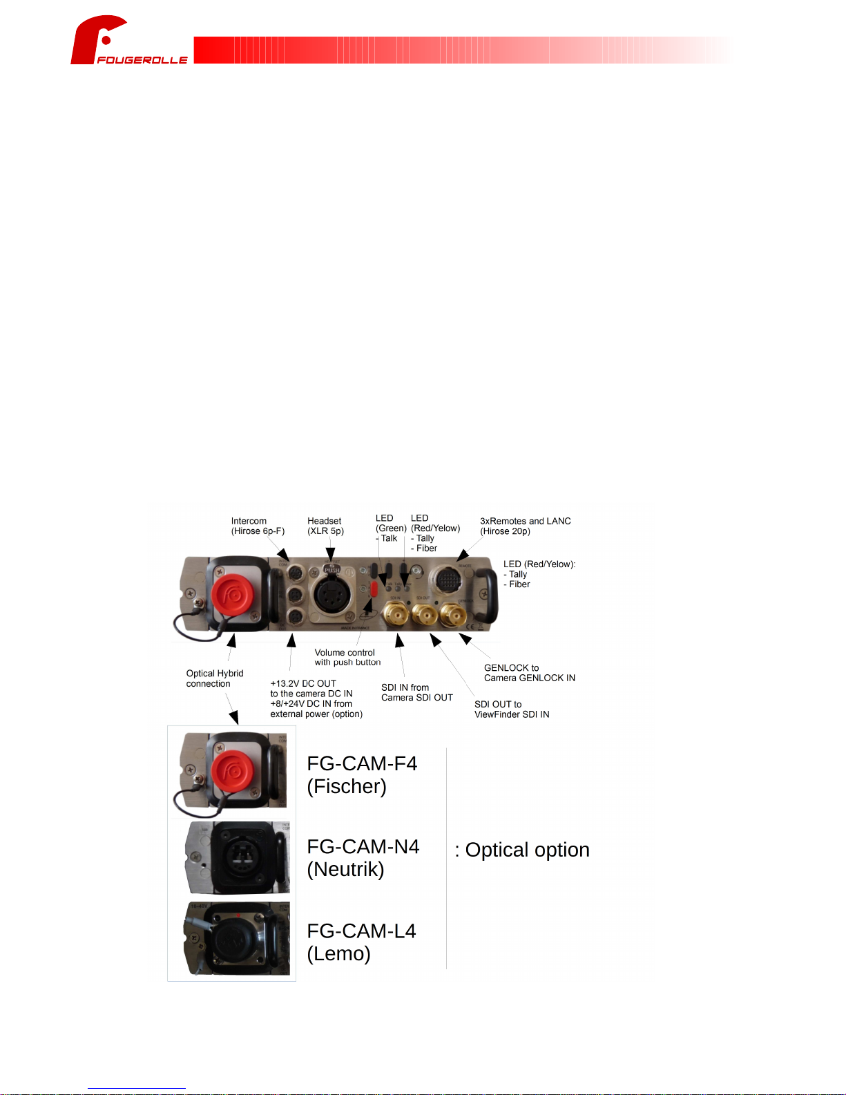
2.2 HEAD UNIT OVERVIEW...............................................................................................8
2.3 BASE UNIT OVERVIEW...............................................................................................9
2.4 HEAD UNIT SHOOTING POSITION.................................................................................10
2.4.1 F
IBRE
ROCKING
SYSTEM
....................................................................................................10
2.4.2 T
ALLY
..........................................................................................................................10
2. CAMI-VL MOUNTING...............................................................................................11
3 OPERATION ................................................................................... 12
3.1 POWER UP...........................................................................................................12
3.2 DC IN................................................................................................................12
3.3 DC OUT............................................................................................................12
3.4 HEADSET: AUDIO SETTINGS – HEAD UNIT...................................................................13
3. HEADSET LIST........................................................................................................13
3.6 AUDIO/HEADSET....................................................................................................14
3.7 INTERCOM.............................................................................................................14
3.8 GENLOCK.............................................................................................................1
3.9 SDI....................................................................................................................1
3.10 REMOTE – RS232/RS422 (REMOTE 1)..................................................................1
3.11 REMOTE – ETHERNET/USB (REMOTE 2)..................................................................1
3.12 REMOTE – RS-232 (TTL REMOTE 3)....................................................................16
3.13 REMOTE – LANC (REMOTE 4)..............................................................................16
4 CONNECTORS PINOUT ................................................................. 17
4.1 BASE UNIT – PINOUT CONNECTORS...........................................................................17
-2-
CamiFlex Base Unit – Head Unit

4.1.1 B
ASE
U
NIT
– R
EMOTE
1 – S
ERIAL
CONNECTION
....................................................................17
4.1.2 B
ASE
U
NIT
– R
EMOTE
2 – E
THERNET
(USB
ON
H
EAD
U
NIT
)..................................................17
4.1.3 B
ASE
U
NIT
– R
EMOTE
3 – S
ERIAL
CONNECTION
....................................................................17
4.1.4 B
ASE
U
NIT
– R
EMOTE
4 – LANC – S
ERIAL
CONNECTION
.......................................................18
4.1. B
ASE
U
NIT
– T
ALLY
CONNECTION
.......................................................................................18
4.1.6 B
ASE
U
NIT
– I
NTERCOM
IN
CONNECTION
..............................................................................19
4.1.7 B
ASE
U
NIT
– I
NTERCOM
OUT
CONNECTION
..........................................................................19
4.1.8 B
ASE
U
NIT
– H
EADSET
IN/OUT
CONNECTION
......................................................................19
4.2 HEAD UNIT – PINOUT CONNECTORS...........................................................................20
4.2.1 H
EAD
U
NIT
– R
EMOTE
/USB/LANC
CONNECTIONS
................................................................20
4.2.2 H
EAD
U
NIT
– I
NTERCOM
IN/OUT
CONNECTION
.....................................................................21
4.2.3 H
EAD
U
NIT
– H
EADSET
IN/OUT
CONNECTION
......................................................................21
4.2.4 H
EAD
U
NIT
– DC IN
CONNECTION
.....................................................................................22
4.2. H
EAD
U
NIT
– DC OUT
FOR
C
AMERA
CONNECTION
...............................................................22
4.2.6 H
EAD
U
NIT
–
EXTERNAL
T
ALLY
CONNECTION
IN
FRONT
OF
H
EAD
U
NIT
.........................................22
TECHNICAL SPECIFICATIONS ..................................................... 23
.1 POWER................................................................................................................23
.2 VIDEO INPUT AND OUTPUT.........................................................................................23
.3 VIDEO SIGNALLING..................................................................................................24
.4 AUDIO/REMOTE.....................................................................................................24
6 ANNEX ............................................................................................ 2
6.1 CAMERA ACCESSORIES.............................................................................................2
-3-
CamiFlex Base Unit – Head Unit

1 INTRODUCTION
1.1 Caution – safety instructions
Please, read these instructions and heed all warnings.
- Do not use this apparatus near water.
- Do not install near any heat sources such as radiators, heat registers, stoves, or other apparatus
(including amplifiers) that produce heat.
- For a full warranty, only use attachments/accessories specified by the manufacturer.
- Refer all servicing to qualified service personnel. Servicing is required when the apparatus has been
damaged in any way, such as power-supply cord or plug is damaged, liquid has been spilled or
objects have fallen into the apparatus, the apparatus has been exposed to rain or moisture, does not
operate normally, or has been dropped.
- To reduce the risk of fire or electric shock, do not expose this product to rain or moisture.
- This device has to be installed by qualified personnel who knows the usual safety procedures and
also follows the recommendations listed in this manual.
- The Base Unit chassis MUST be connected to a power supply with a proper grounding. This power
connector (IEC 320) is the main connector for the network disconnection and must be easily
accessible.
- Both Base Unit and Head Unit must be connected together thanks to hybrid fiber. Connection Base
Unit or Head Unit to another equipment can cause failure and such use may cancel the guarantee.
- The mechanical ground of the equipment must be grounded. It is necessary to use an AC cord with
Earth as the one supplied. If you choose to use another power cord, make sure it is appropriate.
100-240V ~
0/60Hz
1A max
- Real consumption is depending on the power camera need: Lowest consumption value is around
0.3A
- Do not open the equipment when power supply is connected, otherwise there is a risk of electric
shock and death.
Camera does not allow to be powered off by unpluging the DC IN but must be powered down thanks
to camera switch off first.
Turning off the equipment is done with the front panel button.
FOUGEROLLE will not be responsible of any accident to a person or any damage to the equipment
after use of the product without following these safety recommendations. Such use may cancel the
guarantee.
In accordance with current standards, this unit is equipped with a unipolar protection by fuse.
F4AH x20
IEC 127
This means that a voltage is always present in the equipment when the power cord is connected to AC
power. Do not remove the cover of the equipment without unplug the power cord.
-4-
CamiFlex Base Unit – Head Unit

1.2 Services information and Contact
For any question or support use the following contact:
FOUGEROLLE
Rue de la Longueraie
3 20 MELESSE
FRANCE
Tel :+33 (0)2 99 66 08 17 sales @fougerolle-fr.com www.fougerolle-fr.com
1.3 Waste Electrical & Electronic Equipment (WEEE)
This symbol indicate that this product should not be disposed of with household waste, such
as specify the WEEE European Directive (2012/19/EU) and the laws in your country.
This product must be entrusted to a designated collection point, for example, every time you buy a
new similar product or to a collection point for agree recycling the electrical equipment or electronic
(EEE). Inappropriate treatment treating this type of waste is likely to have impacts on environment and
human health due to the presence of potentially hazardous substances generally associated with
electrical or electronic equipment. Your cooperation to the correct disposal of this product will increase
the efficient use of natural resources.
For further information about recycling this product, please contact your local services, your ECO-
organization or the local authorities.
1.4 Restriction of Hazardous Substances (RoHS)
This product is compliant with directive 2012/19/UE, restricts the use of the following six substances:
- Lead (Pb)
- Mercury (Hg)
- Cadmium (Cd)
- Hexavalent chromium (Cr6)
- Polybrominated biphenyls (PBB)
- Polybrominated diphenyl ether (PBDE)
1. Guaranties
A product is faulty if it does not comply with the given description in this manual.
Duration of the guaranty is 3 years for this product against all hidden defects.
The warranty does not include the return shipping costs, degradations of any kind, consequences due
to wrong uses of the product against the recommendations found in this manual and cable made by
the customer.
1.6 EMC and Safety
This product meets all relevant CE:
EMC TESTS REPORT according to the standard(s):
- EN 032: 2012
- EN 103-2: 2009
- EN 61000-3-2: 2014
- EN 61000-3-3: 2013
Safety according to the standard(s):
- IEC 6006 :2001 (Seventh Edition) + A1:200 + A2:2010
- -
CamiFlex Base Unit – Head Unit

1.7 Base Unit – Head Unit
The FG-CAM equipment (also refered as Camiflex in this document) can extend your camera over single mode
hybrid fiber up to 200m (for higher distances, please contact us). It is composed of a base unit located on the
Camera Control Unit (CCU) side, while the Head unit is co-located with the camera.
The Head Unit can be mounted either between the tripod and the camera using a cartoni quick release set option,
or between the camera and its battery using the Vlock docking option.
Compatible with all JVC cameras, this product supports multiple data communication (TTL Serie, RS232, RS422,
LANC) for remote control.
Features:
• 1 x 3G/HD SDI from Head to Base unit
• 1 x 3G/HD SDI from Base to Head unit
• 1 x Genlock from Base to Head unit
• 2 x Tally (Preview / On Air ) integrated on the front of the Head Unit, plus external Tally output via a jack
connector
• 1 x RS-232 / RS-422 configurable + Remote Power: remote 1
• 1 x USB/Ethernet: remote 2 (/U option)
• 1 x RS-232 (TTL remote 3) + Remote Power
• 1 x LANC (remote 4) + Remote Power
• 1 x DC OUT 13.2V to power the camera (up to 40 watts @ 200 meters, contact us if more output power is
required)
• 1 x Single mode hybrid fiber connector
• 1 x Intercom link
• 1 x Microphone/headphone, configurable headset levels thanks to push button on Head Unit
• 1 x DC IN from +8V to +24V for local FG-CAM powered locally (allows to use Tactical Fiber up to 10Km
distance)
Warning: power supply to remote controllers is available directly from the RS connector be careful to not
connect directly the RS port to a computer (See connector PINOUT for details) on CCU side
-6-
CamiFlex Base Unit – Head Unit

1.8 Cami-VL adapter
The Cami-VL adapter can be used to lock the Head Unit between the camera and its battery.
Several ways to use this option:
- If you use Tactical Optical Fiber (or big length of hybrid optical fiber), there will be no power available
to power both Head unit, camera and accessories. In this case, a battery can be used to power the
Camera by using the Cami-VL adapter (see picture below). In this case, the Head Unit can be
powered through an external cable that connects the Head Unit DC IN to the DTAP DC output on the
Cami_VL.
- If you have an hybrid fiber, power supply is available on the Head Unit DC OUT. In this case the
battery is not required and the Head Unit can power the camera by using an external cable connected
between the Head Unit DC OUT and the external DC input of the Camera.
See installation instructions in Cami-VL mounting section
-7-
CamiFlex Base Unit – Head Unit

2 INSTALLATION
2.1 Rack mount - Base Unit
The equipment is designed to be installed in a standard 19" rack or any other support.
The equipment should be placed away from wet projections, with an operating temperature between
+ °C and +40°C.
The mounting of the equipment in the rack should be such that a hazardous situation may not be
completed due to an abnormal mechanical load. Account must be taken for the connection of the
equipment to the power supply and the effect of possible overload protection against overcurrent and
power cables. A study of the characteristics of the equipment must be made.
It is necessary to check the reliability of the grounding of the equipment especially for shunt
connection.
Special extended temperature range products can be produced on customer request.
All equipment connections are done from the rear panel.
The video cables shall not weigh too heavily on the connectors.
The earth connection (bolt with nut) must be connected to the earth of rack.
2.2 Head Unit overview
-8-
CamiFlex Base Unit – Head Unit

2.3 Base Unit overview
Model: FG-CAM-F4/U, FG-CAM-N4/U, FG-CAM-L4/U
/U option: Base Unit with standard RJ4 Ethernet cable and Head unit with LANC+USB cable.
-9-
CamiFlex Base Unit – Head Unit
AC power
input Optical Hybrid
connection
GENLOCK from
Global Generator
SDI OUT to
Switcher SDI IN
SDI IN from
Switcher SDI OUT
LANC
(MiniJack
2. mm 3p)
Intercom IN
(XLR3p F)
Headset
(XLR p)
Intercom OUT
(XLR3p M) Remotes 1&2
(SubD9 F)
Remotes 3
(MiniDIN 6p F)
RJ4
Ethernet
With Loop
LED green :
- signal present
FG-CAM-F4
(Fischer)
FG-CAM-N4
(Neutrik)
FG-CAM-L4
(Lemo)
Optical option :
Tally A&B
(SubD9 M)

2.4 Head Unit shooting position
When Head Unit is located under the camera, the following items can be used
2.4.1 Fibre rocking system
The optical connector can be pull out of the Head Unit in order to release the connector and thus
guide the fibre down to about 4 °.
- To use the system, you need to plug the fibre on Head Unit, then pull gently the connector toward
you to tilt it down.
- To replace the connector, just push it back in the Head Unit.
Rocking s stem
2.4.2 Tally
Tally display is present on top of the Head Unit allowing the cameraman to see whether the signal is
on air or not.
-10-
CamiFlex Base Unit – Head Unit

2. Cami-VL mounting
Inserting the Head Unit inside the Cami-VL V-Lock adapter:
Fasten the set using the 4 crews.
Be careful, those screws are countersunk head M3x10. Other screw MUST NOT be used.
-11-
CamiFlex Base Unit – Head Unit

3 OPERATION
3.1 Power Up
Camera should be switch ON after Base Unit and OFF before. During the product power up, Tally and
Fibre LEDs are blinking in orange indicating the product is booting up. This can take a few seconds.
During the system boot, the fibre LED is lighted in yellow during 2 seconds then switch off if the fibre is
correctly connected. If the fibre LED blinks in red, this means there is a connection problem between
Base Unit and Head Unit.
3.2 DC IN
Head Unit can be powered in 2 ways:
a) Through a Hybrid Fibre: the power supply conveyed on the Hybrid Fibre (48V) is internally
converted by Head Unit for internal and external need (13.2V DC OUT - see next section).
H brid
Fiber
100-240V~ DC OUT
13.2V 40W
Base Unit Head Unit
Head unit can also be powered locally to give power redundancy
H brid
Fiber
100-240V~
DC IN
12V
Base Unit Head Unit
b) Through local power supply: Head Unit is powered by DC IN connector (From +8V to +24V IN).
In such case DC OUT is unused.
Tactical
Fiber
100-240V~
DC IN
12V
Base Unit Head Unit
3.3 DC OUT
The Head Unit provide DC OUT in order to power the Camera + accessories. This output is active
only when using a Hybrid Fibre
The certified maximum output power is 40W under 13.2V at 200 meters.
-12-
CamiFlex Base Unit – Head Unit

3.4 Headset: Audio settings – Head Unit
Several audio settings are available on the head unit:
- push "+" or "-" to adjust the headphone volume.
- push "MIC" and then "+" or "-" to adjust the microphone volume.
- Talk function: the "Talk" LED lights up when the microphone is enabled. 2 modes are available:
Mode 1: Push "Talk" and hold the button to set the microphone (PushToTalk)
Release the button to disable the microphone
Mode 2: Push "Talk" without holding the button to enable the microphone (ON/OFF)
Push "Talk" without holding the button to disable the microphone
Mode ½ can be changed by pushing simultaneous "MIC" and "Talk" buttons.
If needed, it is possible to recall default settings by pressing simultaneously "Talk", "-" and "+" buttons
during seconds (LED flashing). LED will then remain still to indicate that factory settings has been
applied.
By default, the factory settings are Mode1 (PushToTalk) with medium audio level.
Settings are saved automatically 10 seconds after each change, and are recalled after each new boot.
3. Headset list
Headsets needs XLR -points and Female connector to be plugged on to the Head Unit. Dynamic
microphone is needed.
Here is a short list of compliant Headset with the Head unit. Feel free to contact us if your desired
headset is not in this list.
Brand Model
RTS
PH-44R
PH-88R
PH-1 A M
PH-3 A M
HR-1 A M
HR-2 A M
Clearcom
CC-110-X
CC-220-X
CC-300-X
CC-400-X
Bayerdynamic
DT108 with K 109.38 option
DT109 with K 109.38 option
DT280 with K 190.39 or K 190.41 option
DT290 with K 190.39 or K 190.41 option
-13-
CamiFlex Base Unit – Head Unit

3.6 Audio/Headset
Analog balanced audio is transmitted over fibre
-
+
+
-
+15V
-15V
IN+
IN-
Audio input
-
+
+15V
-15V
OUT+
OUT-
Audio output
Audio
Over
Fiber
Headset
-
+
+15V
-15V
10K
Loud
Speaker
X
-
+
+5V
-5V
MIC
10K
H brid
Fiber
+
-
+
-
+
-
+
-
Line
level
Base Unit Head Unit
IN+
IN-
GND
OUT+
OUT-
Headset
GND
MIC
GND
L+
R+
Headset
XLR5
XLR5
3.7 Intercom
4 wires intercom connection:
4 wires intercom connection with 3 Head units:
H brid
Fiber
Base Unit Head Unit
+
-
+
-
+
-
GND
OUT+
OUT-
IN+
IN-
Headset
GND
MIC
GND
L+
R+
Headset
XLR5 XLR5
H brid
Fiber
Head Unit
+
-
GND
MIC
GND
L+
R+
Headset
XLR5
H brid
Fiber
Head Unit
+
-
GND
MIC
GND
L+
R+
Headset
XLR5
+
-
+
-
+
-
+
-
+
-
+
-
+
-
+
-
300R
300R
300R
300R
300R
300R
Base Unit
+
-
+
-
XLR5
Base Unit
+
-
+
-
XLR5
GND
OUT+
OUT-
IN+
IN-
Headset
GND
OUT+
OUT-
IN+
IN-
Headset
-14-
CamiFlex Base Unit – Head Unit

If needed, this intercom connection can support Time Code transmission
H brid
Fiber
Base Unit Head Unit
+
-
+
-
IN+
IN-
GND
OUT+
OUT-
INTERCOM
OUT+
OUT-
GND
IN+
IN-
INTERCOM
Time
Code
H brid
Fiber
Base Unit Head Unit
+
IN+
IN-
GND
OUT+
OUT-
INTERCOM
OUT+
OUT-
GND
IN+
IN-
INTERCOM
Time
Code
XLR3
XLR3 HRS6
XLR3
XLR3 HRS6
Note: 2 wires intercoms are not yet supported. Connecting a 2 wires intercoms may cause damages
to the system.
3.8 Genlock
Genlock is transmitted over CVBS format and supports the insertion of an extra PAL/NTSC video
stream (view finder, Teleprompter)
H brid
Fiber
PAL
NTSC
Base Unit Head Unit
BNC
Genlock
BNC
Genlock
3.9 SDI
A bidirectional SD/HD/3G SDI is available on the product.
H brid
Fiber
SDI
Base Unit Head Unit
BNC
SDI In
BNC
SDI Out
BNC
SDI Out
BNC
SDI In
3.10 Remote – RS232/RS422 (remote 1)
Serial communication (any rate up-to 900Kbps) is available thought the system:
A specific cable has to be used on Head Unit side (Hirose-20 type) and power can be injected to
power the remote control from the Base Unit side.
H brid
Fiber
Base Unit Head Unit
SubD-9 HRS20
W th spec al cable
3.11 Remote – Ethernet/USB (remote 2)
-1 -
CamiFlex Base Unit – Head Unit

3.12 Remote – RS-232 (TTL Remote 3)
RS-232 communication (TTL level, any rate up-to 900Kbps) is available thought the system:
A specific cable has to be used on Head Unit side (Hirose-20 type) and power can be injected to
power the remote control from the Base Unit side.
H brid
Fiber
Base Unit Head Unit
MiniDIN6 HRS20
W th spec al cable
MiniDIN6
MiniDIN6
3.13 Remote – LANC (Remote 4)
LANC remote communication is available thought the system:
A specific cable has to be used on Head Unit side (Hirose-20 type) and power can be injected to
power the remote control from the Base Unit side.
H brid
Fiber
Base Unit Head Unit
Jack HRS20
W th spec al cable
Jack Jack
-16-
CamiFlex Base Unit – Head Unit

4 Connectors Pinout
4.1 Base Unit – Pinout Connectors
4.1.1 Base Unit – Remote 1 – Serial connection
Remote connection is managed through RS232 or RS-422.
For RS-232 configuration, a short-circuit must be done between Pin 4 & Ground (Pin 1 or Pin ).
Baud rate can be up to 700K baud without any specific configuration.
Pin SubD9-F - Remote RS-232 SubD9-F - Remote RS-422(*)
1 - (Do not used) 1 Ground
2 OUT : TxD 2 OUT : RS_TX-
3 IN : TxD 3 IN : RS_RX+
4 RS-4xx (short-circuit to ground) 4 - (Not used)
Ground Ground
6 - (Not used) 6 OUT : RS_TX+
7 - (Not used) 7 - (Not used)
8 - (Not used) 8 IN : RS_RX-
9 - (Not used) → +12V 9 +12V
* Note: Differential RS-422 inputs includes 120R termination resistors
4.1.2 Base Unit – Remote 2 – Ethernet (USB on Head Unit)
Ethernet (RJ4 ) on Base side is used to connect a remote control or other to the
camera through a dedicated Ethernet or USB cable on Head unit side.
4.1.3 Base Unit – Remote 3 – Serial connection
Serial control can be sent through RS-232(TTL level). Baud rate can be up to 9600
baud.
Pin MiniDIN 6p-F - Remote RS232 (TTL level)
1 Ground
2 IN : RS3_RM/CTL
3 Ground
4 OUT : RS3_SID2
IN : RS3_SID1
6 OUT : +12V
-17-
CamiFlex Base Unit – Head Unit
Female connector

4.1.4 Base Unit – Remote 4 – LANC – Serial connection
Bi-directional serial communication is compliant with LANC protocol (9600 baud)
Pin Mini Jack 2. mm 3p - LANC
1 LANC
2 +6V
3 GND
4.1. Base Unit – Tally connection
Tally input pins need to be in short-circuit with ground to turn ON the Tally LED:
- Tally A: Red light
- Tally B: Yellow light
- Both A&B Tally: Red light
Pin SubD9-M – Tally (A&B)
1 Not used
2 Not used
3 Not used
4 Not usedn
Not used
6 Tally A – Red
7 Ground
8 Tally B – Yellow
9 Not used
-18-
CamiFlex Base Unit – Head Unit

4.1.6 Base Unit – Intercom IN connection
Standard XLR 3p connection:
Pin XLR 3p-F – Intercom IN (Line level)
1 GND
2 IN+
3 IN-
4.1.7 Base Unit – Intercom OUT connection
Standard XLR 3p connection:
Pin XLR 3p-M – Intercom OUT (Line level)
1 GND
2 OUT+
3 OUT-
4.1.8 Base Unit – Headset IN/OUT connection
Pin XLR p-F – Headset IN/OUT (Line level)
1 GND
2 OUT+
3 OUT-
4 IN+
IN-
-19-
CamiFlex Base Unit – Head Unit

4.2 Head Unit – Pinout Connectors
4.2.1 Head Unit – Remote/USB/LANC connections
Pin Hirose 20p-F – Remote
1 IN : - RS1_422_RX-
2 IN : RS1_232_RX RS1_422_RX+
3 OUT : RS1_232_TX RS1_422_TX-
4 OUT : - RS1_422_TX+
IN : GND or No connection RS-232: short-circuit to GND
6 Ground configuration for RS1
7 Ground
8 Ground
9 OUT : RS3_SID1
10 IN : RS3_SID2
11 IN : GND or No connection RS-232: short-circuit to GND
12 LANC_Power configuration for RS2
13 Ground
14 Ground
1 OUT : RS3_RM/CTL
16 LANC
17 USB GND
18 USB VCC
19 USB Data +
20 USB Data -
-20-
CamiFlex Base Unit – Head Unit
This manual suits for next models
2
Table of contents
Other JVC Camera Accessories manuals

JVC
JVC WR-DV75U User manual

JVC
JVC KY-F560U - 3-ccd Color Camera User manual

JVC
JVC Marine Case WR-MG100 User manual

JVC
JVC CB-A260U User manual

JVC
JVC GR-DVM50 User manual

JVC
JVC Studio Kit KA-F5602U User manual

JVC
JVC GR-DVM80 User manual

JVC
JVC GY-HD250U - 3-ccd Prohd Camcorder Dimensional drawing

JVC
JVC KA-F5604U User manual

JVC
JVC CARRYING BAG CB-V77U User manual