Thank you for purchasing the JVC option hater unit.
To obtain the best results from your new camera, read these instructions carefully before use;
retain the manual for future reference.
These instructions are for KA-ZH215U
These are general IMPORTANT SAFEGUARDS and certain items may not apply to all appli-
ances.
●To save energy, turn the power off when not in use.
●This unit is a special heater for TK-C215VP4U, TK-C215VP4E, TK-C215VP12U,TK-
C215VP12E (henceforth referred to TK-C215VP series) Dome camera. It cannot be installed
to other color video cameras.
●Use AC 24 V power supply for TK-C215VP series.
●Do not modify this machine without prior permission. Accidents may occur.
●Refer to the instructions for TK-C215VP series on installing the camera and connecting the
cables.
●After installing to TK-C215VP series , switch off the machine power supply and then connect.
●Always use the desiccant that comes with this unit. Other desiccants or the desiccant that
comes with TK-C215VP series are unable to remove moisture completely under extreme low
temperature.
●When the heater board is installed, the switch on the camera unit is hidden and image adjust-
ment cannot be made. Always adjust the image quality before installing the heater.
●Do not use the heater unit in the following locations:
• Locations where the surrounding temperature exceeds -22Jto 122J(-30fto 50f).
• Locations where corrosive gas occurs.
• Vibrating locations
●Do not touch this unit during operation or after operation as its temperature is high.
It may cause a burn.
Mount this unit onto TK-C215VP series.
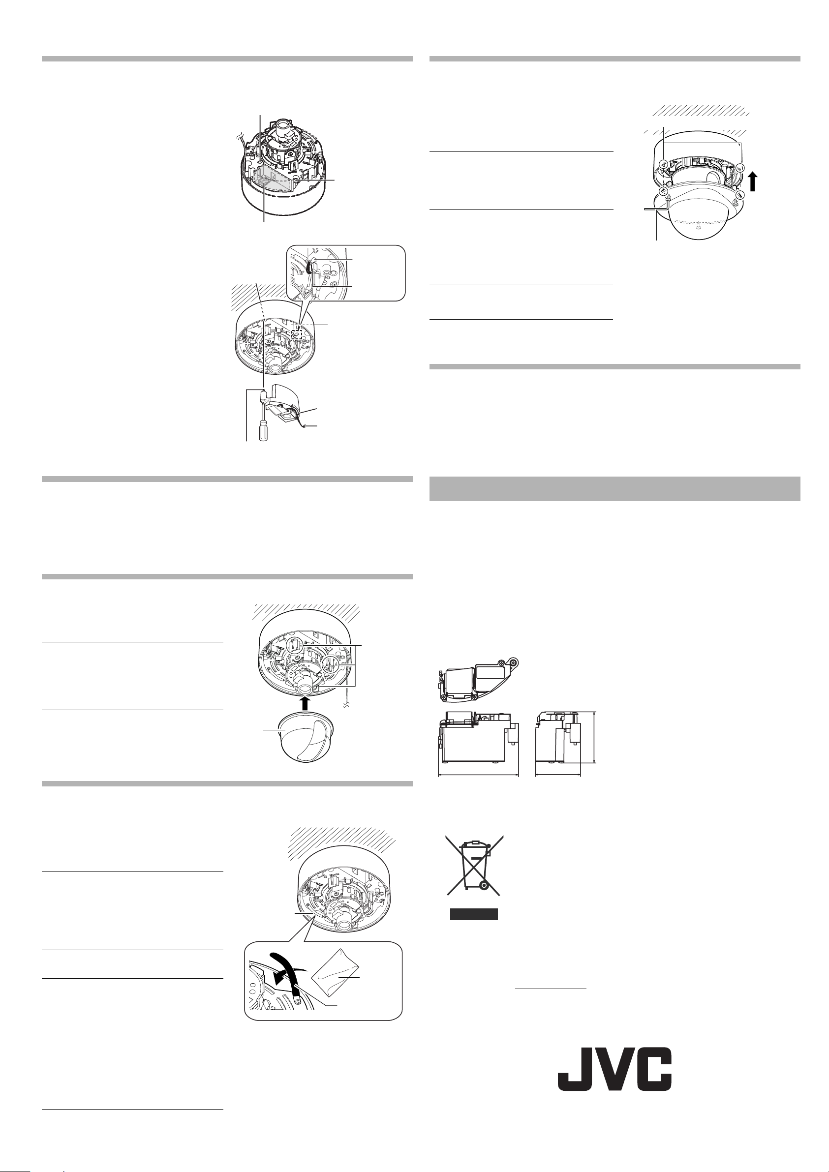
Step1: Disassembling TK-C215VP series
Switch off the power supply of the camera.
1. Removing the dome cover
Remove the dome cover by unfastening the 3
fastening screws using the wrench supplied.
2. Removing the inner dome
The inner dome is fastened using lugs at 3 dif-
ferent positions. Grasp the inner dome and
remove it from the lugs.
HEATER UNIT
KA-ZH215U INSTRUCTIONS
For Customer Use:
Enter below the Serial No. which is located on the
body.
Retain this information for future reference.
Model No.
Serial No.
1. Readall of these instructions.
2. Save these instructionsfor later use.
3. All warningson the product and in the operating instructionsshould beadhered to.
4. Unplug thisappliance system from the wall outlet before cleaning. Do not useliquid cleanersor
aerosol cleaners.Useadamp cloth for cleaning.
5.
Do not useattachmentsnot recommended by the appliance manufacturer as they maycausehazards.
6. Do not use thisappliance nearwater - for example, neara bathtub,washbowl, kitchen sink, or
laundry tub,inawet basement, or nearaswimming pool, etc.
7.
Do not place thisappliance on anunstable cart, stand, or table. The appliance may
fall, causing serious injury to achild or adult, and serious damage to the appliance.
Use only with acart or stand recommended by the manufacturer, or sold with the
appliance. Wall or shelf mounting should follow the manufacturer'sinstructions,
and should useamounting kit approved by the manufacturer. An appliance and
cart combination should be moved with care.
Quick stops, excessive force, and uneven surfacesmaycause the appliance and
cart combination to overturn.
8. Slotsand openingsin the cabinet and the back or bottom are pro-vided for
ventilation, and to insure reliable operation of the appliance and to protect it from
overheating, these openingsmust not beblocked or covered. The openings
should never beblocked byplacing the appliance on abed, sofa,rug, or other similarsurface.
Thisappliance should never beplaced near or over aradiator or heat register. Thisappliance should
not beplaced in abuilt-in installation such asabookcaseunless proper ventilation isprovided.
9.
Thisappliance should be operated only from the type of power source indicated on the marking label.
If youare not sure of the type of power supplied to your home, consult your dealer or local power
company. For appliance designed to operate from battery power, refer to the operating instructions.
10.For added protection for thisproduct during alightning storm, or when it isleft unattended and
unused for long periodsof time, unplug it form the wall outlet and disconnect the antennaor cable
system. Thiswill prevent damage to the product due to lightning and power-line surges.
11.Do not allow anything to rest on the power cord. Do not locate thisappliance where the cord will be
abused by personswalking on it.
12.Follow all warningsand instructionsmarked on the appliance.
13.Do not overloadwall outletsand extension cordsasthiscanresult in fire or electric shock.
14.Never pushobjectsof any kind into thisappliance through cabinet slotsasthey maytouch
dangerous voltage pointsor short outpartsthat could result in afire or electric shock. Never spill
liquid of any kind on the appliance.
15.Do not attempt to service thisappliance yourself as opening or removing coversmay exposeyouto
dangerous voltage or other hazards. Refer all servicing to qualified service personnel.
16.Unplug thisappliance from the wall outlet and refer servicing to qualified service personnel under
the following conditions:
a. When the power cord or plugisdamaged or frayed.
b. If liquid has been spilled into the appliance.
c. If the appliance has been exposed to rain or water.
d. If the appliance doesnot operate normally by following the operating instructions. Adjust only those controls
thatare covered by the operating instructionsasimproper adjustment of other controlsmay result in damage
and will often require extensive work bya qualified techniciantorestore the appliance to normal operation.
e. If the appliance has been dropped or the cabinet has been damaged.
f. When the appliance exhibitsadistinct change in performance - thisindicatesaneed for service.
17.When replacement partsare required, besure the service technicianhas used replacement parts
specified by the manufacturer thathave the same characteristicsasthe originalpart. Unauthorized
substitutionsmayresult in fire, electric shock, or other hazards.
18.Upon completion of any service or repairsto thisappliance, ask the service technician to perform
routine safety checksto determine that the appliance isin safe operating condition.
IMPORTANT SAFEGUARDS
PORTABLE CART WARNING
(symbol provided by RETAC)
S3125A
RISK OF ELECTRIC SHOCK
DO NOT OPEN
CAUTION
FOR USA AND CANADA
ThisClass B digitalapparatus complieswith
Canadian ICES-003.
Duetodesign modifications,datagiven in this
instruction book are subject to possible change
without prior notice.
WARNING:
TO REDUCE THE RISK OF FIRE OR
ELECTRIC SHOCK, DO NOT EXPOSE
THIS APPLIANCE TO RAIN OR
MOISTURE.
AVERTISSEMENT:
POUR EVITER LES RISQUES
D'INCENDIE OU D'ELECTROCUTION,
NE PAS EXPOSER L'APPAREIL A
L'HUMIDITE OU A LA PLUIE.
INFORMATION (FOR CANADA)
RENSEIGNEMENT (POUR CANADA)
The lightning flashwisharrowhead
symbol, within anequilateral triangle
isintended to alert the user to the presence
of uninsulated "dangerous voltage" within
the product'senclosure thatmaybeof
sufficient magnitude to constitute ariskof
electric shock to persons.
The exclamation point within an
equilateral triangle isintended to alert
theuser to the presence of important
operating and maintenance (servicing)
instructionsin the literature
accompanying the appliance.
Cet appareil numeriquedelaClasseBest
conforme alanorme NMB-003duCanada.
TO REDUCE THE RISK OF ELECTRIC
SHOCK. DO NOT REMOVE COVER (OR
BACK). NO USER-SERVICEABLE PARTS
INSIDE.REFER SERVICING TO
QUALIFIED SERVICE PERSONNEL.
CAUTION :
INFORMATION FOR USA
■INFORMATION
This equipment has been tested and found to comply with the limits for a Class B digital device, pursuant
to Part 15 of the FCC Rules.
These limits are designed to provide reasonable protection against harmful interference in a residential
installation. This equipment generates, uses, and can radiate radio frequency energy and, if not installed
and used in accordance with the instructions, may cause harmful interference to radio communications.
However, there is no guarantee that interference will not occur in a particular installation.
If this equipment does cause harmful interference to radio or television reception, which can be
determined by turning the equipment off and on, the user is encouraged to try to correct the interference
by one or more of the following measures:
• Reorient or relocate the receiving antenna.
• Increase the separation between the equipment and receiver.
• Connect the equipment into an outlet on a circuit different from that to which the receiver is con-
nected.
• Consult the dealer or an experienced radio/TV technician for help.
■CAUTION
CHANGES OR MODIFICATIONS NOT APPROVED BY JVC COULD VOID USER’S AUTHORITY TO
OPERATE THE EQUIPMENT.
PRECAUTION
Contents
Installation Method
Memo
●The dome cover and base are connected
with fall prevention wire.
Note
●Before touching the camera unit, make
sure to touch the metal surface of the
[MONITOR] terminal to discharge any
static electricity from your body. Static
electricity may cause the camera to mal-
function.
Dear Customer,
This apparatus is in conformance with the valid European directives and standards regarding
electromagnetic compatibility and electrical safety.
European representative of Victor Company of Japan Limited.is:
JVC Technology Centre Europe GmbH
P.O.Box 10 05 52
61145 Friedberg
Germany
Instructions
1
Warranty Card
1Service Information Card
1
Desiccant
(Service Parts
No.LW40790-001A)
1
HEATER UNIT
1
Wrench
(Supplied)
Fall Prevention
Wire
Inner
Dome
Lug(x 3)
*TK-C215VP4 is used in the illustration.
LST0472-001A