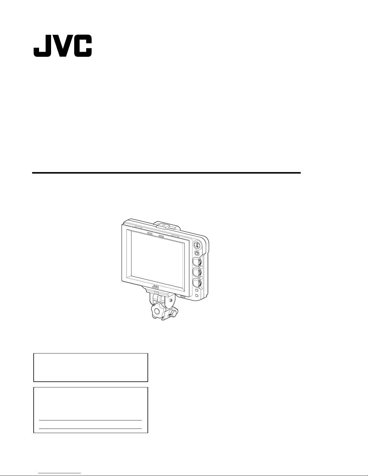
JVC GY-HM750U User manual

For Customer Use:
Enter below the Serial No. which is located on the
body.
Retain this information for future reference.
Model No.
Serial No.
Thank you for purchasing this JVC product.
efore beginning to operate this unit, please read
the instructions carefully to ensure the best
possible performance.
STUDIOVIEWFINDER
VF-HP790G INSTRUCTIONS
LST1110-001A
VF-HP790G

II
Introdu tion
1.
Read all of these instructions.
2.
Save these instructions for later use.
P RTABLE CART WARNING
(symbol provided by RETAC)
S3125A
IMPORTANT SAFEGUARDS
4.
Unplug this appliance system from the wall outlet before cleaning. Do not use liquid cleaners or aerosol
cleaners. Use a damp cloth for cleaning.
5.
Do not use attachments not recommended by the appliance manufacturer as they may cause hazards.
6.
Do not use this appliance near water - for example, near a bathtub, washbowl, kitchen sink, or laundry tub, in a wet
basement, or near a swimming pool, etc.
7.
Do not place this appliance on an unstable cart, stand, or table. The appliance may fall,
causing serious injury to a child or adult, and serious damage to the appliance.
Use only with a cart or stand recommended by the manufacturer, or sold with the appliance.
Wall or shelf mounting should follow the manufacturer's instructions, and should use a
mounting kit approved by the manufacturer. An appliance and cart combination should be
moved with care.
Quick stops, excessive force, and uneven surfaces may cause the appliance and cart
combination to overturn.
8.
Slots and openings in the cabinet and the back or bottom are provided for ventilation, and to insure reliable operation of
the appliance and to protect it from overheating, these openings must not be blocked or covered. The openings should
never be blocked by placing the appliance on a bed, sofa, rug, or other similar surface.
This appliance should never be placed near or over a radiator or heat register.
This appliance should not be placed in a built-in installation such as a bookcase unless proper ventilation is provided.
9.
This appliance should be operated only from the type of power source indicated on the marking label. If you are not sure
of the type of power supplied to your home, consult your dealer or local power company. For appliance designed to
operate from battery power, refer to the operating instructions.
10.
For added protection for this product during a lightning storm, or when it is left unattended and unused for long periods
of time, unplug it form the wall outlet and disconnect the antenna or cable system. This will prevent damage to the
product due to lightning and power-line surges.
These are general IMPORTANT SAFEGUARDSand ertain items may not apply to all applian es.
3.
All warnings on the product and in the operating instructions should be adhered to.
FOR USA
14.
Never push objects of any kind into this appliance through cabinet slots as they may touch dangerous voltage points or
short out parts that could result in a fire or electric shock. Never spill liquid of any kind on the appliance.
15.
Do not attempt to service this appliance yourself as opening or removing covers may expose you to dangerous voltage
or other hazards. Refer all servicing to qualified service personnel.
16.
Unplug this appliance from the wall outlet and refer servicing to qualified service personnel under the following conditions:
a. When the power cord or plug is damaged or frayed.
b. If liquid has been spilled into the appliance.
c. If the appliance has been exposed to rain or water.
d.
e. If the appliance has been dropped or the cabinet has been damaged.
f.
If the appliance does not operate normally by following the operating instructions. Adjust only those controls that
are covered by the operating instructions as improper adjustment of other controls may result in damage and will
often require extensive work by a qualified technician to restore the appliance to normal operation.
When the appliance exhibits a distinct change in performance - this indicates a need for service.
17.
When replacement parts are required, be sure the service technician has used replacement parts specified by the
manufacturer that have the same characteristics as the original part. Unauthorized substitutions may result in fire,
electric shock, or other hazards.
18.
Upon completion of any service or repairs to this appliance, ask the service technician to perform routine safety checks
to determine that the appliance is in safe operating condition.
13.
Do not overload wall outlets and extension cords as this can result in fire or electric shock.
12.
Follow all warnings and instructions marked on the appliance.
11.
Do not allow anything to rest on the power cord. Do not locate this appliance where the cord will be abused by persons
walking on it.

III
SafetyPre autions
CAUTI N:
RISK FELECTRICSH CK
D N T PEN
CAUTION
FORUSAANDCANADA
T REDUCE THE RISK F ELECTRIC
SH CK. D N T REM VE C VER ( R
BACK).
N USER-SERVICEABLE PARTSINSIDE .
REFER SERVICING T QUALIFIED
SERVICE PERS NNEL.
Theexclamationpointwithinanequilateral
triangleisintendedtoalerttheusertothe
presenceofimportantoperatingand
maintenance(servicing)instructionsinthe
literatureaccompanyingtheappliance.
INF RMATI N:
Thisequipmenthasbeentestedandfoundtocomplywiththelimits
foraClassAdigitaldevice,pursuanttoPart15oftheFCCRules.
Theselimitsaredesignedtoprovidereasonableprotectionagainst
harmfulinterferencewhentheequipmentisoperatedina
commercialenvironment.
Thisequipmentgenerates,uses,andcanradiateradiofrequency
energyand,ifnotinstalledandusedinaccordancewiththe
instructionmanual,maycauseharmfulinterferencetoradio
communications.
perationofthisequipmentinaresidentialareaislikelytocause
harmfulinterferenceinwhichcasetheuserwillberequiredtocorrect
theinterferenceathisownexpense.
CAUTI N:
CHANGES RM DIFICAT I NSN TAPPR VEDBYJVC
C ULDV IDUSER’SAUTH RITYT PERATETHE
EQUIPMENT.
THISDEVICEC MPLIESWITHPART 15 FTHEFCC
RULES.
PERAT I NISSUBJECTT THEF LL WINGTW
C NDITI NS:(1)THISDEVICEMAY N TCAUSE
HARMFULINTERFERENCE,AND(2)THISDEVICEMUST
ACCEPTANYINTERFERENCERECEIVED,INCLUDING
INTERFERENCETHATMAYCAUSE UNDESIRED
PERAT I N.
Thelightningflashwitharrowheadsymbol,
withinanequilateraltriangleisintendedto
alerttheusertothepresenceofuninsulated
“dangerousvoltage”withintheproduct’s
enclosurethatmaybeofsufficientmagnitude
toconstituteariskofelectricshockto
persons.
POURCANADA
ATTENTION
RISQUED’ELECTR CUTI NNE
PAS UVRIR
ATT ENTI N:
P UREVITERT UTRISQUED’ELECTR CUTI N
NEPAS UVRIRLEB ITER.
AUCUNEPIECEINTERIEUREN’ESTAREGLER
PARL’UTILISATEUR.
SEREFERERAUNAGENTQUALIFIEENCASDE
PR BLEME.
Lesymboledel’éclairàl’intérieurd’untriangle
équilatéralestdestinéàalerterl’utilisateursurla
présenced’une“tensiondangereuse”nonisolée
dansleboîtierduproduit.Cettetensionest
suffisantepourprovoquerl’électrocutionde
personnes.
Lepointd’exclamationàl’intérieurd’untriangle
équilatéralestdestinéàalerterl’utilisateursurla
présenced’opérationsd’entretienimportantesau
sujetdesquellesdesrenseignementssetrouvent
danslemanueld’instructions.
Cessymbolesnesontutilisésqu’auxEtats-Unis.
INFORMATION(FORCANADA)
RENSEIGNEMENT(POURCANADA)
ThisClassAdigitalapparatuscomplieswithCanadian
ICES-003.
CetappareilnumériquedelaClassAestconformeàla
normeNMB-003duCanada.
WARNING:
TOREDUCETHERISKOFFIREORELECTRIC
SHOCK,DONOTEXPOSETHISAPPLIANCETORAIN
ORMOISTURE.
CAUTION:
Thisunitshouldbeusedwith12VDConly.
Topreventelectricshocksandfirehazards,doN Tuseany
otherpowersource.
AVERTISSEMENT:
ATTENTION:
Cemagnétoscopenedoitêtreutiliséquesurducourantdirecten12V.
Afind’evitertoutresqued’incendieoud’electrocution,nepasutillserd’autres
sourcesd’alimentationélectrique.
POUREVITERLESRISQUESD’INCENDIEOU
D’ELECTROCUTION,NEPASEXPOSERL’APPAREILA
L’HUMIDITEOUALAPLUIE.
NOTE:
Theratingplate(serialnumberplate)isontheunit.
REMARQUE:
Laplaquesignalétique(plaquedunumérodesérie)estsituéesur
lecadreinférieurdel’unité.
CAUTION:
Topreventelectricshock,donotopenthecabinet.Nouser
serviceablepartsinside.Referservicingtoqualifiedservice
personnel.
Duetodesignmodifications,datagiveninthisinstructionbook
aresubjecttopossiblechangewithoutpriornotice.
Theapparatusshallnotbeexposedtodrippingorsplashingand
thatnoobjectsfilledwithliquids,suchasvases,shallbeplaced
closetotheapparatus.

IV
Introdu tion
FOR EUROPE
Thisequipmentisinconformitywiththeprovisionsand
protectionrequirementsofthecorrespondingEuropean
Directives.Thisequipmentisdesignedforprofessionalvideo
appliancesandcanbeusedinthefollowingenvironments:
ControlledEMCenvironment(forexample,purpose-built
broad-castingorrecordingstudio),andruraloutdoors
environments.
Inordertokeepthebestperformanceandfurthermorefor
electromagneticcompatibilitywerecommendtousecables
notexceedingthefollowinglengths:
SafetyPre autions
( ontinued)
Port Cable Length
VFCABLE ShieldCable 0.58m
DCCABLE ShieldCable 5m
SDIINPUT CoaxialCable 2m
Caution:
Where there are strong electromagnetic waves or magnetism, for
example near a radio or TV transmitter, transformer, motor, etc.,
the picture and the sound may be disturbed. In such case, please
keep the apparatus away from the sources of the disturbance.
DearCustomer,
ThisapparatusisinconformancewiththevalidEuropeandirectivesand
standardsregardingelectromagneticcompatibilityandelectricalsafety.
EuropeanrepresentativeofVictorCompanyofJapan,Limitedis:
JVCTechnicalServicesEuropeGmbH
Postfach100504
61145Friedberg
Germany
SehrgeehrterKunde,sehrgeehrteKundin,
diesesGerätstimmtmitdengültigeneuropäischenRichtlinienund
NormenbezüglichelektromagnetischerVerträglichkeitund
elektrischerSicherheitüberein.
DieeuropäischeVertretungfürdieVictorCompanyofJapan,
Limitedist:
JVCTechnicalServicesEuropeGmbH
Postfach100504
61145Friedberg
Deutschland
Information for Users on Disposal of Old Equipment
[European Union]
This symbol indicates that the electrical and electronic
equipment should not be disposed as general household
waste at its end-of-life. Instead, the product should be handed
over to the applicable collection point for the recycling of
electrical and electronic equipment for proper treatment,
recovery and recycling in accordance with your national
legislation.
By disposing of this product correctly, you will help to conserve
natural resources and will help prevent potential negative
effects on the environment and human health which could
otherwise be caused by inappropriate waste handling of this
product. For more information about collection point and
recycling of this product, please contact your local municipal
office, your household waste disposal service or the shop
where you purchased the product.
Penalties may be applicable
for incorrect disposal of this waste, in accordance with national
legislation.
(Business users)
If you wish to dispose of this product, please visit our web
page http://www.jvc.eu to obtain information about the take-
back of the product.
[Other Countries outside the European Union]
If you wish to dispose of this product, please do so in
accordance with applicable national legislation or other rules
in your country for the treatment of old electrical and
electronic equipment.
Attention:
This symbol is only valid in the European
Union.

1
Introdu tion
Features ....................................... 1
PrecautionsDuringUse ........................... 2
NamesofPartsandFunctions(Front) ................ 3
NamesofPartsandFunctions(Rear) ................. 4
Setup
Installation ...................................... 5
MountingonKA-790G .......................... 5
RemovingtheViewfinder ........................ 5
ConnectingVFCable........................... 5
MountingtheHoodCover(Provided)............... 6
AdjustingthePosition ............................. 6
DisplayingtheImages ............................. 6
AdjustingthePictureQuality ........................ 6
Menu
SettingtheMenu ................................. 7
SettingtheMenuofthisViewfinder ................ 7
EnteringtheCameraName ...................... 7
ReturningMenuSettingstoDefaultSettings ......... 7
SettingtheCameraMenuoftheGY-HM790Series .... 7
MenuScreen .................................... 8
MAINMENUScreen ............................ 8
MARKERSETTINGMenuScreen................. 9
SH TINGASSISTMenuScreen................ 10
VIDE F RMATMenuScreen................... 11
THERSMenuScreen......................... 12
PrecautionswhenUsingwiththeGY-HM790Series..... 12
Others
TerminalSpecifications........................... 13
Troubleshooting ................................. 14
Specifications .................................. 14
Thisproductisan8.4-inchcolorviewfinderforuseinthe
GY-HM790CHU/GY-HM790U/GY-HM790CHE/GY-HM790E/
KA-790Gstudiosystem.
HighResolution
Alargeviewfinderwithan8.4-inchXGA(1024x768)LCD
panel.
MultiS an
SupportsYPbPrinputofHD(1080i50/60,720p50/60)and
SD(480i60,576i50).
[SDIINPUT]Terminal
Inadditiontothecamera’sviewfinderimage,SDIimagecan
beinputtothisviewfinder.
Ri hMarker
EquippedwithSafetyZonedisplay,twotypesofZebradisplay
andFocusAssistfunction,allofwhicharehighlyusefulinthe
studio.
S reenMenuFun tion
Youcandisplaythemenuonthescreentosetoradjustthe
mostappropriatemonitorsettingsfortheconnectingsystem.
Youcanmakesettingstothemenusofthisviewfinderandthe
GY-HM790seriescamera(exceptforsomeparts).
TableofContentsFeatures
Howtousethismanual
Symbolsused
Note :Describesprecautionsconcerningtheoperation
ofthisproduct.
Memo :Describesreferenceinformation,suchas
functionsandusagerestrictionsofthisproduct.
A:Indicatesthereferencepagenumbersand
referenceitems.
Contentofthismanual
AllrightsreservedbyJVC.Unauthorizedduplicationor
reprintingofthismanual,inwholeorinpart,isstrictly
prohibited.
Allotherproductnamesusedinthismanualarethe
trademarksorregisteredtrademarksoftherespective
companies.Markssuchas™,,andhavebeen
omittedinthismanual.
Illustrateddesigns,specificationsandothercontentsof
thismanualaresubjecttochangeforimprovement
withoutpriornotice.

2
Introdu tion
Lo ationofStorageandUse
Donotplacethisproductatthefollowinglocations.
Doingsomaycausetheproducttomalfunctionorbreak
down.
Hotorcoldplacesbeyondtheallowableoperating
temperaturerangeof0 °Cto+40 °C.
Humidplacesbeyondtheallowablehumidityrangeof
30%RHto80%RH(non-condensing).
Placesinthevicinityofastrongmagneticfield,suchas
neartransformersormotors.
Nearequipmentthatemitradiowaves,suchas
transceiversormobilephones.
Placesthataresubjecttodustorsand.
Placesthataresubjecttostrongvibrations.
Placesthataresusceptibletocondensation,suchas
nearwindows.
Placesthataresubjecttovapororoil,suchaskitchens.
PlacesthatemitradioactiveraysorX-rays,and
corrosivegases.
Noisemayoccurintheimagesorthecolorsmaychange
whenthisproductanditsconnectingwireareusedin
placessubjectedtostrongradioormagneticwaves(e.g.,
nearradios,TVs,transformers,ormonitors).
HandlingtheProdu t
Insufficientventilationmayresultinmalfunctionofthis
product.Makesurethatobjectsplacedaroundthisproduct
donotobstructitsventilation.
Donotplacecontainersfilledwithwater(vases,plants,
cups,cosmetics,drugsandsoon)ontopofthisproduct.
Watergettingintotheinterioroftheequipmentmayresult
infireandelectricshock.
MovingtheProdu t
Removeconnectingcablesbeforemovingthisproduct.
Whenmovingthisproduct,dosoafterturningoffthepowerof
theconnectingcamera,andmakesuretounplugthecable
fromthisproduct.Failuretodosomaydamagethecable,
causingfireorelectricshock.
Maintenan e
Turnoffthepoweroftheconnectingcamerabefore
performingmaintenanceofthisproduct.
Useasoftclothtowipetheproduct.Donotwipeusing
thinnerorbenzene,asdoingsomaycausethesurfaceto
meltorturncloudy.Whenthereissignificantsoiling,wipe
usingaclothbydippingitinaneutraldetergentthatis
dilutedwithwater,followedbycleaningusingadrycloth.
Theexteriorofthisproductmaychangeorthepaintmay
falloffwhencomeintocontactwithrubberorvinylproducts
foraprolongedperiodoftime.
EnergyConservation
Whenthisproductisnotusedforaprolongedperiodoftime,
turnoffthepowerofthesystemforsafetyandenergy
conservationpurposes.
LCDS reen
LeavingtheLCDscreenexposedtothesunwilldamagethe
LCDscreen.Donotplacetheproductoutdoorsorneara
window.
DonotscratchorpresshardontheLCDscreen,orplace
objectsontopofthescreen.Blotchesmayappearonthe
screenandleadtomalfunctionoftheLCDpanel.
Whenusingtheproductincoldplaces,horizontalstripesand
trailingimagesmayappearorthescreenmayappeardark.
Thesearenotmalfunctions.Thescreenwillappearnormal
againwhenthetemperaturerises.
Continuousdisplayofstillimagesmaycauseresidualimages.
Thescreenwillreturntonormalaftersometime.
Whentheproductisinuse,thescreenorcabinetmay
becomewarm.Thisisnotamalfunction.
Bright/DarkSpots
Brightspots(red,blueorgreen)anddarkspotsthatare
continuouslylitupmayappearonthescreen.
AnLCDpanelismanufacturedwithextremelyprecise
technology.Althoughitconsistsofmorethan99.99%
effectivepixels,itmayexhibitaverysmallnumberof
continuousbrightordarkspotsonthescreen.
MaintainingtheLCDS reen
ThesurfaceofanLCDscreenisspeciallytreatedtocontrol
reflectionsoffthesurface.Impropermaintenancemayaffect
theperformanceofthescreen.Assuch,pleaseadheretothe
followingpoints.
Useasoftclothsuchasacleaningclothorspectacles
cleaningclothtolightlywipeoffanydirtonthesurfaceof
thescreen.
Whenthereissignificantsoiling,wipeusingasoftcloth
suchasacleaningclothorspectaclescleaningcloth
soakedwithabitofwater.
Donotusealcohol,benzene,thinner,acidic,alkalineor
abrasivecleaningfluid,orchemicalwipingclothtoclean
thescreenastheywillscratchthesurface.
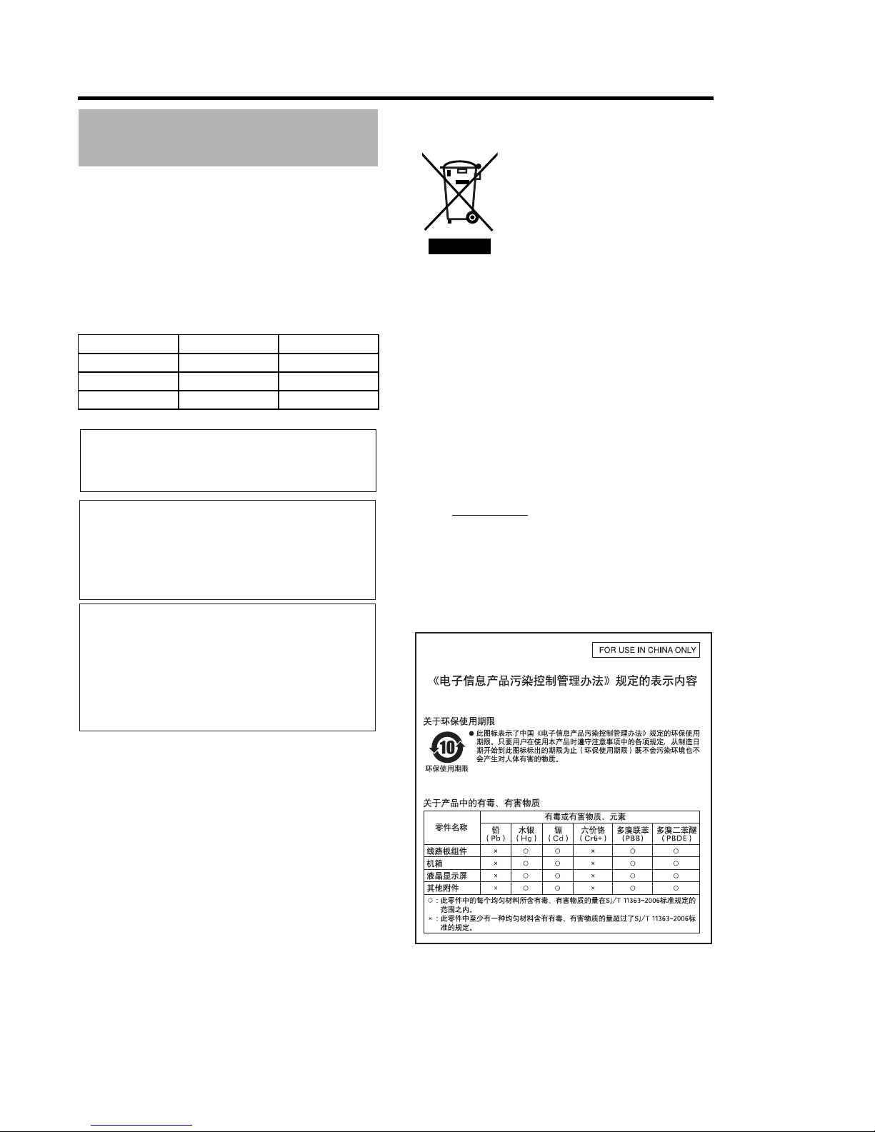
Disposal
Donotdisposethisproductwithothernormalwaste
products.
Donotthrowthemonitorintotherubbishthatwillbesentto
thedumping-ground.
Thefluorescenttubeofthisproductcontainsmercury.
Followtherulesandregulationsofthelocalauthoritiesfor
disposal.
Pre autionsDuringUse

3
A[MENU]Dial(Button)
Whenthenormalscreenisdisplayed,pressthisdialfor
morethan1secondtodisplaythemenuofthecamera.
Themenuofthecameraisdisplayedwhenthe
[INPUTS URCE]settingofthisviewfinderissetto[VF]
andtheGY-HM790seriesisinthecameramode.
Whenthemenuofthisviewfinderisdisplayed,scrollthis
dialupanddowntomovethecursor(�)upanddownto
selectanitem.
Whenthemenuofthecameraisdisplayed,usethisdialto
selectthemenuitemandsettingvalue.Pressthedialto
confirmtheselecteditem.
B[STATUS/MENU]Button
Whenthenormalscreenisdisplayed,pressthisbuttonto
displaytheadditionalinformation.Theadditional
informationthatisdisplayedvariesaccordingtotheinput
image.
Imagefromthecamera’sviewfinder:
Displaysof[CAMERANAME]or[SAFETYZ NE],
[CENTERMARK],[ASPECTMARKER],[ZEBRA],
[SP TMETER],[STATUS]setintheGY-HM790series.
Imagefromthisviewfinder’s[SDIINPUT]terminal:
Displaysof[SAFETYZ NE],[CENTERMARK],
[ASPECTMARKER],[ZEBRA],[CAMERANAME]setinthe
menuofthisviewfinder.
Whenthenormalscreenisdisplayed,pressthisbuttonfor
morethan1secondtodisplaythemenuofthisviewfinder.
Whenthemenuofthecameraisdisplayed,themenu
displayswitcheseverytimethisbuttonispressedformore
than1second.
(Camera’smenu1[FavoritesMenu])
Whenthemenuofthisviewfinderorthecamerais
displayed,pressthisbuttontoreturntothenormalscreen.
Memo
Additionalinformationdoesnotappearin[1:1]display.
Thestatusofdisplayingorhidingtheadditionalinformation
isnotsaved.Andtheadditionalinformationisalways
displayeduponstartup.
C[BRIGHT]AdjustmentControl
Foradjustingthebrightnessofthescreen.Turntotherightto
brightenandtothelefttodarken.
Memo
Whenthecamera’sviewfinderimageisinput,the[VF
BRIGHT]adjustmentknobonthecameraisdisabled.
D[CONTRAST]AdjustmentControl
Foradjustingthecontrastofthescreen.Turntotherightto
increasethecontrastandtothelefttodecreasethecontrast.
E[PEAKING]AdjustmentControl
Foradjustingthepeakingofthescreen.Turntotherightto
sharpenthecontourandtothelefttosoften.
Memo
ThisadjustmentcontrolisdisabledwhentheFocusAssist
isactivated.
Whenthecamera’sviewfinderimageisinput,the[VF
PEAKING]adjustmentknobonthecameraisdisabled.
F[1:1]Button
MakesfocusingeasierwhendisplayingHDvideos.
Pressthisbuttontodisplaytheinputvideosignalsin1:1ratio
withoutresizing.The[ASPECTMARKER],[SAFETYZ NE],
[CENTERMARK],[ZEBRA],[SP TMETER],
[CAMERANAME],[CAMERASTATUS]displaywillbe
temporarily�FFBduringthisdisplay.
Memo
Controlstatusofthe[1:1]buttonisnotsaved.
Thisbuttonisdisabledwhen[INPUTS URCE]issetto
�SDIBandSD-SDIsignalsareinputfromthe
[SDIINPUT]terminal.
[1:1]displayis�FFBinthefollowingcases.
Whenthepoweristurnedon
Whenthemenuofthisviewfinderorthecamerais
displayed
Whenthevideoformatofthedisplayimageischanged
Whenchangedtothereturnvideo
G[FOCUSASSIST]Button
Pressthisbuttontodisplaythefocussectionincolor.
Accuratefocusingcanbedone.(PEAKINGcannotbe
adjusted.)
Memo
Thecolorandlevelofthefocussectioncanbechangedat
theMenuscreen.(APage 10)
WhenconnectedtotheGY-HM790series,the
[F CUSASSIST]buttononthecameraisdisabled.
Whenthereturnvideoisdisplayed,thesettingofthe
[F CUSASSIST]buttononthisviewfinderisdisabled.
WhenconnectedtotheGY-HM790series,theviewfinder
willnotoperateunderthefollowingconditions.
DuringBARS N,SKINC L RADJUSTorSKINAREA
SW N
HTALLYLamp
Displaysthemonitorstatusoftheinputscreen,eitherinredor
green.
WhenTallyPGM(Program)signalsareinput,thelamplights
upinred.
WhenTallyPVM(Preview)signalsareinput,thelamplights
upingreen.
WhenCALLsignalsareinput,thelampblinksinred.
NamesofPartsand
Fun tions(Front)
MENU
STATUS
BRIGHT
C NTRAST
PEAKING
1:1
F CUS
ASSIST
5
6
4
5
6
4
C
D
E
F
G
H
A
B

4
Introdu tion
ITALLYLamp
Displaysthemonitorstatusoftheinputscreeninred.
ThelamplightsupinredonlywhenTallyPGM(Program)
signalsareinput.
Memo
Use[TALLY]switchKtoturn N/ FFthedisplayfunction
ofthislamp.
JVFCABLEHOLDER
ForclampingtheprovidedVFcablewhenconnectingittothe
inputterminal.
Memo
WhenconnectingtheVFcable,securethecablewiththe
holdertopreventitfromdisconnecting.(APage 5)
K[TALLY]Swit h
Forturning N/ FFtheTALLYlampI.
N :TALLYisenabled.
FF :TALLYisdisabled.
Memo
ThisswitchdoesnotaffecttheoperationoftheTALLY
lampsHonthescreen.
LDIPSwit h
Donottouchastheswitchfunctioniscurrentlynotavailable.
M[VFCABLE]InputTerminal
ForconnectingtotheVFoutputterminal(20-pin)ofthe
GY-HM790seriesusingtheprovidedVFcable.
N[SDIINPUT]Terminal
TheinputterminalforSDIvideosignals.
Todisplaytheimagefromthisterminal,set[INPUTS URCE]
inthe[VIDE F RMAT]menuto�SDIB.(APage 11)
Tousetheimagefromthisterminalasreturnsignals,set
[SDIRETURN]to�NBwhile[INPUTS URCE]isbeingset
to�VFB.
Memo
Youcanselectthedesiredvideoformatusing
[FRAMERATE]and[F RMAT]inthe[VIDE F RMAT]
menu.(APage 11)
O[DCINPUT]Terminal(XLRtype,4-pin)
Thisviewfindercanbeoperatedbyconnectingtoanexternal
powersupplyofDC12V.(Whenthisviewfinderisconnected
totheGY-HM790series,itisnotnecessarytoconnectan
externalpowersupplytothisterminal.)
NamesofPartsand
Fun tions(Rear)
DCINPUT
SDIINPUT
VFCABLE TALLY
N
FF
K
M
N
O
J
�
L

5
Setup
MountingonKA-790G
1Rotatethelo kleverinthearrowdire tion( )
asshowninthediagrambelow.
2Alignthebra ketforviewfindermountontopof
KA-790Gwiththegrooveattheviewfindermount
baseandinsertfromtheba kofthe amerahead.
3Rotatetheviewfinderlo kleverinthearrow
dire tion( )asshownbelowandse urethe
viewfindertoKA-790G.
RemovingtheViewfinder
1WhilepressingtheReleasebutton,slidethe
viewfindertowardtheba kofthe ameraheadand
remove.
Conne tingVFCable
BeforeconnectingtheVFcable,besuretoturnoffthe
P WERswitchonthecameraorontheremotecontrolunit.
Connecttheviewfinder’s[VFCABLE]terminaltothe[VF]
terminaloftheGY-HM790serieswiththeprovidedVFcable.
Note
Besuretousethecableprovidedwiththisviewfinder.
ThecableprovidedwithVF-HP840Ucannotbeused.
1InserttheprovidedVF ablefullytothe[VF
CABLE]terminal.
2Loosenthesetsrewonthe ableholder,tiltthe
holderatanangleandinserttheVF ablefromthe
bottomintothegrooveontheholder.
3Pressthe ableholdersquarelyagainstthe
viewfinderandse urethesetsrew.
Ifthecableholderisslanted,thesetscrewcannotbesecured
anditmaydamagethescrewholeontheviewfinder.
Note
Besuretoturnofftheviewfinderandthecamerabefore
connectingordisconnectingthecable.
Installation
1
2
3
MountBase
BracketforViewfinderMount
LockLever
1
2
Push
ReleaseButton
LockLever
VFCable
CableHolder
SetScrew
VFCable
(Good) (Nogood)

6
Setup
MountingtheHoodCover(Provided)
1Alignthehood overwiththegrooveontopof
theviewfindersreenandinsertfromthetop.
2Se urewiththesrewlo atedatthe enter,
belowtheviewfindersreen.
1Loosenthepanningandtiltlo khandletoadjust
theangleoftheviewfinderandse ureitatan
appropriateangleforeasyviewing.
Memo
ItmaybedifficulttoviewtheLCDscreenatsomeangles.
Viewfromthedirectfrontangleofthescreen.
1SetthePOWERswit honremote ontrolunitor
amerato�ONB,todisplaytheimageonthe
viewfinder.
Memo
Dependingonthesystemenvironment,itmaytakeupto
10secondsbeforetheimageisdisplayed.
Selecttheimagetodisplayusing[INPUTS URCE]inthe
[VIDE F RMAT]menu.(Imagefromthecamera’s
viewfinderorthisviewfinder’s[SDIINPUT]terminal)
(APage 11)
1Turnthe[BRIGHT] ontroltoadjustthe
brightnessofthesreen.
Tobrighten,turntotheright.
2Turnthe[CONTRAST] ontroltoadjustthe
ontrastofthesreen.
Toincreasethecontrast,turntotheright.
3Turnthe[PEAKING] ontroltoadjustthe
peaking.
Tosharpenthecontour,turntotheright.
Memo
Youcansetthefrequencybandwherethecontouris
emphasizedwiththe[PEAKING]controlin
[PEAKINGFREQ.]ofthe[SH TINGASSIST]menu
screen.(APage 11)
YoucanadjustthebrightnessoftheLCDbacklightusing
[BACKLIGHT]inthe[ THERS]menu.(APage 12)
Whenthisviewfinderisused,itsdisplayisalwayson
regardlessofthe[LCD+VF]settinginthe[LCD+VF]menu
oftheGY-HM790series.
Note
Afterswitchingoffthepoweronthecameraorremote
controlunit,waitfor10secondsormorebeforeturningon
thepowerswitchagain.
Turning N/ FFthepowerswitchinquicksuccessionmay
causemalfunction.
Installation( ontinued)
AdjustingthePosition
Screw
Panning
Tilt
PanningandTiltLockHandle
DisplayingtheImages
AdjustingthePi tureQuality
MENU
STATUS
BRIGHT
C NTRAST
PEAKING
1:1
F CUS
ASSIST
5
6
4
5
6
4
[BRIGHT]Control
[C NTRAST]Control
[PEAKING]Control

7
Menu
SettingtheMenuofthisViewfinder
1Pressthe[STATUS/MENU]buttonfor1se ond
ormoreduringnormalsreendisplay.
The[MAINMENU]screenappears.
2Turnthe[MENU]dialtomovethe ursortothe
desiredmenusreen.
3Pressthe[MENU]dial.
Theselectedmenuscreenappears.
Selecting[EXIT]onthe[MAINMENU]screenwillreturn
thescreentothenormalscreen.
4Turnthe[MENU]dialtomovethe ursortothe
itemtobesetandpressthe[MENU]dial.
Thesettingvalueoftheitemblinks.
Selecting[PAGEBACK]onthemenuscreenwillreturnthe
screentothe[MAINMENU]screen.
5Turnthe[MENU]dialto hangethesettingvalue.
6Pressthe[MENU]dialtostoptheblinkingofthe
settingvalue.
Thesettingvalueissavedatthispoint.
7To hangeothersettings,repeattheabovesteps
3to6.
8Afterallsettingsare omplete,pressthe
[STATUS/MENU]button.
Thisreturnstothenormalscreen.
EnteringtheCameraName
1Displaythe[OTHERS]menusreen.
2Turnthe[MENU]dialtomovethe ursorto
[NAMEEDIT].
3Pressthe[MENU]dial.
Thefirstcharacterblinks.
4Turnthe[MENU]dialtosele tany hara ter.
5Pressthe[MENU]dialto onfirmthe hara ter.
Thenextcharacterblinks.
6Repeattheabovesteps4and5toenter6
hara ters.
Toenteratitleoflessthan6characters,usespace.
7Afterallthe hara tersareentered,pressthe
[STATUS/MENU]button.
Thisreturnstothenormalscreen.
Memo
TodisplaythecameranameontheStatusscreen,set
[CAMERANAME]inthe[ THERS]menuscreento�NB.
ReturningMenuSettingstoDefaultSettings
Atthe[ THERS]menuscreen,set[MENURESET]to
�EXECUTEBandpressthe[MENU]dialtoreturnthemenu
settingstodefaultsettings.
SettingtheCameraMenuoftheGY-HM790Series
Themenuofthecameracanbesetwhen[INPUTS URCE]
issetto�VFBandtheGY-HM790seriesisintheCamera
mode.
1Whenthenormalsreenisdisplayed,pressthe
[MENU]dialformorethan1se ond.
Thecamera’s[MAINMENU]screenappears.
2
Followthepro edurefromstep2onwardsin
[SettingtheMenuofthisViewfinder](
A
Page 7).
Memo
Whenthemenuofthecameraisdisplayed,themenu
displayswitcheseverytimethe[STATUS/MENU]buttonis
pressedformorethan1second.
(Camera’smenu1[FavoritesMenu])
perationsthatinvolvemovingthecursorhorizontally
cannotbeperformedonthisviewfinder.
Fordetailsonthemenuofthecamera,refertothe
[INSTRUCTI NS]oftheGY-HM790series.
SettingtheMenu
MENU
STATUS
BRIGHT
C NTRAST
PEAKING
1:1
F CUS
ASSIST
5
6
4
5
6
4
[MENU]Dial
[STATUS/MENU]
Button
- -
M
A I N
M
EN U - -
M
A RK ER S E T T I NG. .
SH T I NG A S S I S T. .
V I D E F R
M
A T. .
T H ER S. .
E X I T
- -
M
A RK E R S E T T I NG - -
A S P E C T T Y P E V I DE
R A T I 1 6 : 9
P S I T I N CE N T E R
A S P E C T
M
A RK E R N
T Y P E L I NE + H A L F
S A F E T Y Z NE N
S I Z E 9 5
%
C EN T E R
M
AR K N
P AGE B AC K
- - T H ER S - -
CA
M
ERA N A
M
E N
N AME E D I T
H P 7 9 0 G
B L AC K&
W
H I T E C L R
M
E NU R E S E T C A NC E L
P AGE B AC K
B A C K L I G H T MAX

8
Menu
TheMenuscreenconsistsofthefollowingstructureasshownbelow.
MAINMENUS reen
MenuS reen
- -
M
A RK E R S E T T I NG - -
A S P E C T T Y P E V I D E
RA T I 1 6 : 9
P S I T I N C EN T E R
A S P E C T
M
A RK E R N
T Y P E L I NE + H A L F
S A F E T Y Z NE N
S I Z E 9 5
%
C EN T E R
M
ARK N
P AG E B A C K
- -
M
A I N
M
ENU - -
M
A RK ER S E T T I NG. .
S H T I NG A S S I S T . .
V I D E F R
M
A T. .
T HE R S. .
E X I T
- - S H T I NG A S S I S T - -
F CU S AS S I S T B L U E
L E V E L
M
I DD L E
Z E B R A 2 P A T T E RN S
T P 1 8 0
%
B T T
M
1 7 0
%
T P 2 V E R
B T T
M
2 8 0
%
P E A K I NG F R EQ .
M
I DD L E
P AG E B A C K
- - V I D E F R
M
A T - -
I N PU T S U RCE V F
I N PU T S I GN A L A U
T
F R A ME R A T E
-
-
- -
F R
M
A T -
-
- -
A S P E C T [ SD] 4 : 3
P AG E B A C K
- - T H ER S - -
C A
M
ERA N A
M
E N
N A ME E D I T
HP 7 9 0 G
B L ACK &
W
H I T E C L R
P AG E B A C K
B A C K L I G H T MAX
MENURESETCANCEL
SDIRETURN
F
F
MenuS reen Desription
MARKERSETTING.. Thisitemsetsthevariousmarkerstobedisplayedintheimages.
SH TINGASSIST.. Thisitemsetstheshootingassistfunction.
VIDE F RMAT.. ThisitemsetstheformatforvideoinputorSDIvideoinput.
THERS.. Thisitemsetsthecameranameandinitializesthemenu.
EXIT Thisreturnstothenormalscreen.

9
MARKERSETTINGMenuS reen
Settingsinboldarefactorydefaultsettings.
Memo
The[MARKERSETTING]menuisvalidfortheimagefromthisviewfinder’s[SDIINPUT]terminal.When[INPUTS URCE]in
the[VIDE F RMAT]menuissetto�VFB,allitemsinthe[MARKERSETTING]menuappearas�----Bandcannotbe
selected.Fortheimagefromthecamera’sviewfinder,setthe[MarkerSetting]menuonthecamerabyusingthe[MENU]dialto
controlthemenuofthecamera(APage 7).
Item SettingValue Description
ASPECTTYPE VIDEO
CINEMA
Thisitemsetsthepurposeofthemarker.
VIDE :AspectforTVbroadcastshooting.
CINEMA :Aspectforcinemashooting.
Memo
Whentheinputformatis4:3,�CINEMABcannotbeselected. ([VIDE ]isdisplayed.)
RATIO
Thisitemsetstheaspectratioofthemarker.Itdisplaystheconfiguredaspectratioofthe
marker.Whensetto�16:9+4:3B,the16:9and4:3markeraredisplayedatthesame
time.
Memo
�16:9+4:3BisdisplayedwhentheVIDE F RMATatthecameraisHDmode.
WhenASPECT
TYPEissetto
�VIDEOB
16:9
4:3
14:9
16:9+4:3
WhenASPECT
TYPEissetto
�CINEMAB
2.35:1
1:66:1
1:75:1
1:85:1
POSITION CENTER
C.HEADRM
Thisitemsetsthedisplaypositionofthemarker.
CENTER :Setsthedisplaypositionofthemarkeratthecenterofthescreen.
C.HEADRM :Setsthedisplaypositionofthemarkerattheuppersideofthescreen.
Memo
�C.HEADRMBcanonlybesetwhen[RATI ]is�2.35:1Bor�1:85:1B.Forother
settings,[CENTER]willbedisplayedandsettingisdisabled.
ASPECTMARKER FF
ON
Thisitemsetsthemarkeroutsidetheaspectarea.
FF :Cancelsthemarkeroutsidetheaspectarea.
N :Displaysthemarkeroutsidetheaspectarea.
Memo
WhencameraoutputissettoBARS,thisfunctionis�FFBduringReturnVideo
display,1:1displayandwhenstatusdisplayis FF.
TYPE LINE
HALFT NE
LINE+HALF
Thisitemsetsthetypeoflabelingformarkersoutsidetheaspectarea.
LINE :Displaystheaspectareainlines.
HALFT NE :Displaystheimageleveloutsidetheaspectareainhalfthebrightness.
LINE+HALF :Displaystheaspectareainlinesandsetsoutsidetheareainhalfthe
brightness.
SAFETYZONE FF
ON
Thisitemsetsthemarkerinsidetheaspectarea.
FF :Cancelsthemarkerinsidetheaspectarea.
N :Displaysthemarkerinsidetheaspectarea.
Memo
WhencameraoutputissettoBARS,thisfunctionis�FFBduringReturnVideo
display,1:1displayandwhenstatusdisplayis FF.
SIZE 95%,
93%,90%
88%,80%
Thisitemsetsthedisplaypercentageformarkersinsidetheaspectarea.
CENTERMARK FF
ON
Thisitemsetswhethertodisplaymarkersinthecenter.
FF :Cancelsthecentermarker.
N :Displaysthecentermarker.
Memo
WhencameraoutputissettoBARS,thisfunctionis�FFBduringReturnVideo
display,1:1displayandwhenstatusdisplayis FF.
PAGEBACK ^Thisreturnstothe[MAINMENU]screen.

1�
Menu
SHOOTINGASSISTMenuS reen
Settingsinboldarefactorydefaultsettings.
MenuS reen( ontinued)
Item SettingValue Description
FOCUSASSIST RED
GREEN
BLUE
ThisitemsetsthedisplaycolorofthefocussectionwhentheF CUSASSIST
functionisoperated.
Thisitemisenabledwhen[INPUTS URCE]inthe[VIDE F RMAT]menuissetto
�SDIB.
RED :Displaysthefocussectioninred.
GREEN :Displaysthefocussectioningreen.
BLUE :Displaysthefocussectioninblue.
Memo
When[INPUTS URCE]inthe[VIDE F RMAT]menuissetto�VFB,allitemsin
the[MARKERSETTING]menuappearas�----Bandcannotbeselected.Forthe
imagefromthecamera’sviewfinder,setthe[MarkerSetting]menubyusingthe
[MENU]dialtocontrolthemenuofthecamera(APage 7).
The[F RMAT]buttonoftheGY-HM790seriesisdisabled.
LEVEL L W
MIDDLE
HIGH
ThisitemsetsthefocuslevelduringtheF CUSASSISToperation.
L W :Displaysthefocussection.
MIDDLE :Emphasizesthefocussection.
HIGH :Furtheremphasizesthefocussection.
ZEBRA OFF
1PATTERN
2PATTERNS
SelectwhethertodisplayZebraandthedisplayformat.
Thisitemisenabledwhen[INPUTS URCE]inthe[VIDE F RMAT]menuissetto
�SDIB.
FF :DoesnotdisplayZebra.
1PATTERN :Displaysthebrightnesssetbetween[T P1]and[B TT M1]inZebra.
2PATTERNS :Inadditionto[1PATTERN],thisdisplaysthebrightnesssetbetween
[T P2]and[B TT M2]inZebra.
Memo
When[INPUTS URCE]inthe[VIDE F RMAT]menuissetto�VFB,allitemsin
the[MARKERSETTING]menuappearas�----Bandcannotbeselected.Forthe
imagefromthecamera’sviewfinder,setthisfunctionusingthe[MENU]dialto
controlthemenuofthecamera(APage 7).
TOP1
5%~
80%
~100%
VER
ThisitemsetstheupperlimitofthebrightnessofZebra1.
5%~100% :DisplaysthebrightnessbelowthissettingasZebra.(Thevaluecanbe
setinintervalsof5%.)
VER :CancelstheupperlimitofthebrightnessofthedisplayedZebra.
Memo
When[ZEBRA]issetto
�
FF
B
,
�
-----
B
willbedisplayedandsettingisdisabled.
BOTTOM1
0%~
70%
~100%
ThisitemsetsthelowerlimitofthebrightnessofZebra1.
0%~100% :DisplaysthebrightnessabovethissettingasZebra.(Thevaluecan
besetinintervalsof5%.)
Memo
When[ZEBRA]issetto
�
FF
B
,
�
-----
B
willbedisplayedandsettingisdisabled.
TOP2
5%~100%
OVER
ThisitemsetstheupperlimitofthebrightnessofZebra2.
5%~100% :DisplaysthebrightnessbelowthissettingasZebra.(Thevaluecanbe
setinintervalsof5%.)
VER :CancelstheupperlimitofthebrightnessofthedisplayedZebra.
Memo
When[ZEBRA]issetto�FFBor�1PATTERNB,�-----Bwillbedisplayedand
settingisdisabled.
BOTTOM2
0%~
80%
~100%
ThisitemsetsthelowerlimitofthebrightnessofZebra2.
0%~100% :DisplaysthebrightnessabovethissettingasZebra.(Thevaluecanbe
setinintervalsof5%.)
Memo
When[ZEBRA]issetto�FFBor�1PATTERNB,[----]willbedisplayedandsetting
isdisabled.

11
VIDEOFORMATMenuS reen
Settingsinboldarefactorydefaultsettings.
Item SettingValue Description
PEAKINGFREQ. L W
MIDDLE
HIGH
Thisitemsetsthefrequencybandwherethecontourisemphasizedwiththe
[PEAKING]control.
L W :Emphasizesthelowfrequencyband.
MIDDLE :Emphasizestheintermediatefrequencyband.
HIGH :Emphasizesthehighfrequencyband.
Memo
ThisitemisdisabledwhentheFocusAssistisactivated.
PAGEBACK ^Thisreturnstothe[MAINMENU]screen.
Item SettingValue Description
INPUTSOURCE VF
SDI
SelecttheinputimagetodisplayontheLCDscreen.
VF :Inputstheimagefromthecamera’sviewfinder.
SDI :Inputstheimagefromthisviewfinder’s[SDIINPUT]terminal.
SDIRETURN OFF
N
Thisitemsetswhethertousethesignalsinputtothisviewfinder’s[SDIINPUT]
terminalasreturnsignals.
FF : Returnsignalsaresuppliedbythecamera.Doesnotusethesignalsinputtothe
[SDIINPUT]terminal.
N : Usesthesignalsinputtothe[SDIINPUT]terminalasthereturnsignals.
Memo
When[INPUTS URCE]issetto�SDIB,thisitemappearsas�----Bandcannot
beselected.
INPUTSIGNAL AUTO
MANUAL
Selectwhethertoautomaticallydetectthevideoformatoftheinputsignals.
AUT :Automaticallydetectsthevideoformat.
MANUAL :Thevideoformatisnotautomaticallydetected;selectthevideoformat
using[FRAMERATE]or[F RMAT].
Memo
Whenthereturnvideoisinput,setthisitemto�AUT B.
FRAMERATE 60
50
Thisitemsetstheframerateoftheinputsignals.
60:Selectthiswhentheframerateoftheinputsignalsis60Hz.
50:Selectthiswhentheframerateoftheinputsignalsis50Hz.
Memo
When[INPUTSIGNAL]issetto�AUT B,thisitemappearsas�----Bandcannot
beselected.
FORMAT Selecttheformatoftheinputsignals.
1080I :SelectthiswhentheinputsignalisHD1080i.
720P :SelectthiswhentheinputsignalisHD720p.
480I :SelectthiswhentheinputsignalisSD480i.
576I :SelectthiswhentheinputsignalisSD576i.
Memo
When[INPUTSIGNAL]issetto�AUT B,thisitemappearsas�----Bandcannot
beselected.
If[SystemDefinition]oftheGY-HM790seriesissetto�SD(DV)Bwhen
[INPUTS URCE]issetto�VFB,select�1080IB.
Whenthisitemissetto�720PBwhilethe[INPUTS URCE]issetto�VFB,the
returnvideosuppliedbythecameraisnotdisplayed.
�480IBor�576IBcanonlybeselectedwhen[INPUTS URCE]issetto�SDIB.
WhenFRAME
RATEissetto
60
1080I
720P
480I
WhenFRAME
RATEissetto
50
1080I
720P
576I
ASPECT[SD] 4:3
16:9
ThisitemsetstheaspectofthescreendisplaywhenSDsignalsareinput.
ThisitemisenabledonlywhenSDIsignalsareinputtothe[SDIINPUT]terminal
while[INPUTS URCE]inthe[VIDE F RMAT]menuissetto�SDIB.
4:3 :Displays4:3inputsignalsas-is.
16:9 :Displays4:3imagesin16:9.Thisisvalidwhentheinputsignalsareat
SQUEEZE.
PAGEBACK ^Thisreturnstothe[MAINMENU]screen.

12
Menu
OTHERSMenuS reen
Settingsinboldarefactorydefaultsettings.
Itemswithrestri tedoperationatVF-HP790Gdependingon amerasettings
MenuS reen( ontinued)
Item SettingValue Description
CAMERANAME FF
ON
ThisitemsetswhethertodisplaythecameranameontheSTATUSscreen.
FF :Doesnotdisplay.
N :Display.
Memo
ThecameranameisnotdisplayedduringMENUdisplay.
NAMEEDIT AtoZ,0to9,
-./[]
Enterthecameraname.
Upto6characterscanbeentered.(APage 7)
Thedefaultsettingis�HP790GB.
BLACK&WHITE COLOR
B&W
Thisallowstheimagestobeviewedinblackandwhite.
Thisitemisenabledwhen[INPUTS URCE]inthe[VIDE F RMAT]menuissetto
�SDIB.(APage 11)
C L R : Displayscolorimages.
B&W : DisplaysB&Wimages.
Memo
Fortheimagefromthecamera’sviewfinder,setthisfunctionbyusingthe[MENU]
dialtocontrolthemenuofthecamera(APage 7).
BACKLIGHT MIN,1to9,MAX ThisitemadjuststhebrightnessoftheLCDbacklight.
Increasethevaluetoincreasethebrightness.
MENURESET CANCEL
EXECUTE
Thisitemreturnsallmenusettingstofactorydefaultsettings.
CANCEL :CancelsMenuReset.
EXECUTE :ExecutesMenuReset.
PAGEBACK ^Thisreturnstothe[MAINMENU]screen.
Pre autionswhenUsing
withtheGY-HM790Series
SettingItem SettingValue Restricted peration
TallySystem Studio TheTALLYlampdisplaysTALLY(PGM/PVM),CALLandwarningfromtheremote
control.
therthanStudio TheTALLYlampdisplaysthecameraoperationstatusandwarning.

13
Others
VFTerminal
20-pinConnector
DCINPUTTerminal
4-pinConnector
TerminalSpe ifi ations
PinNo. Name IN/ UT
1 D0+ IN
2 GND0 ^
3GND ^
4 12V IN
5 SCL(D3-) IN
6 D0- IN
7 CLK+ IN
8 CLK- IN
9 GNDC ^
10 SDA(D3+) IN
11 D1+ IN
12 GND1 ^
13D2+ IN
14 GND ^
15 VF_SEN(GND3) IN
16 D1- IN
17 GND2 ^
18 D2- IN
19 NRESET IN/ UT
20 VF_D_IN UT
PinNo. Name IN/ UT
1 GND ^
2 NC ^
3NC ^
4 +12V IN
345
2
1
89 10
7
6
1314 1512
11
18 19 2017
16
1
23
4
345
2
1
89 10
7
6
1314 1512
11
18 19 20
17
16
[VFCABLE]Connector [DCINPUT]Connector

14
Others
General
ConnectingDevice : GY-HM790series
PowerSupply : 12VDC
(11VDCto18VDC)
PowerConsumption : Approx.11Wand
below
AmbientTemperature : 0°Cto40°C
Allowable peratingHumidity : 30%RHto80%RH
Mass : 1.6kg(excludinghood)
1.9kg(includinghood)
LCDSpe ifi ations
ScreenSize : 8.4inch
AspectRatio : 4:3
LCDPanel : TFT-LCD
Resolution : 1024x768dots(XGA)
DisplayColor : Approx.16.77million
colors
ViewAngle(Standard) : 60°/50°/65°/65°
(Top/Bottom/Left/Right)
Brightness :300cd/m²
ContrastRatio : 400:1
InputTerminal
SDIInput : HD/SDSDIvideosignalinput,BNC
(unbalanced)
HD-SDI : CompliantwithSMPTE259M
SD-SDI : CompliantwithSMPTE292M
A essories
Instructions...........................................................................1
WarrantyCard(ForUSA&Canada) ....................................1
VFCable ..............................................................................1
HoodCover ..........................................................................1
Troubleshooting
TroubleshootingChe kPoint
Powerdoesnotturnon InserttheVFcableorpowercablefully.
TurnonthepowersupplyoftheGY-HM790series/RM-HP250.
TherearenoimagesInserttheVFcablefully.
TurnonthepowersupplyoftheGY-HM790series/RM-HP250andsetthecorrect
settings.
Checkthesettingof[INPUTS URCE]inthe[VIDE F RMAT]menu.(APage 11)
Is[INPUTSIGNAL]inthe[VIDE F RMAT]menusetto�MANUALB?Inthiscase,
setitto�AUT Borsetthevideoformatcorrectly.(APage 11)
Thecolorisincorrect/Thereisnocolor InserttheVFcableorpowercablefully.
Adjustthe[C NTRAST]and[BRIGHT]adjustmentcontrols.
Is[BLACK&WHITE]inthe[ THERS]menusetto�B&WB?Inthiscase,setitto
�C L RB.(APage 12)
BlurryimagesAdjustthe[BRIGHT]and[PEAKING]adjustmentcontrols.
Thefieldanglesizeoftheviewfinderis
wrong
Checkthesettingsonpage 11.
Theimagesappeardistorted Checkthesettingsonpage 11.
Spe ifi ations

15
DimensionalOutlineDrawing(Unit:mm)
* Thespecificationsandappearanceofthisproductandotherrelatedproductsmaybemodifiedforimprovementwithoutprior
notice.
WithHood WithoutHood
261
130
261
195
184
90
67
12
MENU
STATUS
BRIGHT
C NTRAST
PEAKING
1:1
F CUS
ASSIST
5
6
4
5
6
4
5
6
4

LST1110-001A
VF-HP790GSTUDIOVIEWFINDER
©2010VictorCompanyofJapan,Limited
Other manuals for GY-HM750U
2
This manual suits for next models
2
Other JVC Camera Accessories manuals

JVC
JVC CU-V550U User manual

JVC
JVC KA-DV5000 User manual

JVC
JVC WB-1540U User manual

JVC
JVC Ceiling Bracket WB-S623U User manual

JVC
JVC GR-DVM50 User manual

JVC
JVC CB-V210U User manual

JVC
JVC KA-790G User manual

JVC
JVC WR-MG88U User manual

JVC
JVC TK-N1100U - Color/monochrome 2-ccd Camera User manual

JVC
JVC GR-DVM80 User manual

JVC
JVC GR-DV3 User manual

JVC
JVC RM-LP100U User manual

JVC
JVC DPT 115 User manual

JVC
JVC Studio Kit KA-F5602U User manual

JVC
JVC CARRYING BAG CB-V77U User manual

JVC
JVC KA-F5604U User manual

JVC
JVC WR-MG77 User manual

JVC
JVC Marine Case WR-MG100 User manual

JVC
JVC CU-V70KITE User manual

JVC
JVC WR-DVXU User manual