18
EINFÜHRUNG
Sicherheitshinweise
(Für Europa)
Dieses Gerät erfüllt die Normen und Schutzbestimmungen der
zutreffenden europäischen Richtlinien.
Das vorliegende Gerät wurde für professionelle Videoanwendungen
entwickelt und kann in den folgenden Umgebungen eingesetzt werden:
zUmgebung mit kontrollierter elektromagnetischer Verträglichkeit
(EMV) (z. B. speziell gebautes Sende- oder Aufnahmestudio) und
im Freien ländlicher Umgebungen.
Um eine optimale Leistung sowie eine elektromagnetische Kompati-
bilität sicherzustellen, empfehlen wir die Verwendung von Kabeln,
die die folgende Länge nicht übersteigen:
Achtung: In der Nähe von starken elektromagnetischen Wellen
oder magnetischen Gegenständen, wie beispielsweise Radio- oder
Fernsehsendeanlagen, Transformatoren, Motoren usw., können Bild
und Ton gestört sein. Stellen Sie in diesen Fällen das Gerät weiter
entfernt von den Störquellen auf.
Benutzerinformationen zur Entsor-
gung alter Geräte
[Europäische Union]
Dieses Symbol zeigt an, dass das elektrische bzw. elektroni-
sche Gerät nicht als normaler Haushaltsabfall entsorgt wer-
den soll. Stattdessen sollte das Produkt zur fachgerechten
Entsorgung, Weiterverwendung und Wiederverwertung in
Übereinstimmung mit der Landesgesetzgebung einer ent-
sprechenden Sammelstelle für das Recycling elektrischer
und elektronischer Geräte zugeführt werden.
Die korrekte Entsorgung dieses Produkts dient dem Umwelt-
schutz und verhindert mögliche Schäden für die Umwelt und
die menschliche Gesundheit, welche durch unsachgemäße
Behandlung des Produkts auftreten können. Weitere Infor-
mationen zu Sammelstellen und dem Recycling dieses Pro-
dukts erhalten Sie bei Ihrer Gemeindeverwaltung, Ihrem
örtlichen Entsorgungsunternehmen oder in dem Geschäft, in
dem Sie das Produkt gekauft haben.
Für die nicht fachgerechte Entsorgung dieses Abfalls können
gemäß der Landesgesetzgebung Strafen ausgesprochen
werden.
(Geschäftskunden)
Wenn Sie dieses Produkt entsorgen möchten, besuchen Sie
bitte unsere Webseite www.jvc-europe.com, um Informatio-
nen zur Rücknahme des Produkts zu erhalten.
[Andere Länder außerhalb der Europäischen Union]
Wenn Sie dieses Produkt entsorgen möchten, halten Sie
sich dabei bitte an die entsprechenden Landesgesetze und
andere Regelungen in Ihrem Land zur Behandlung elektri-
scher und elektronischer Geräte.
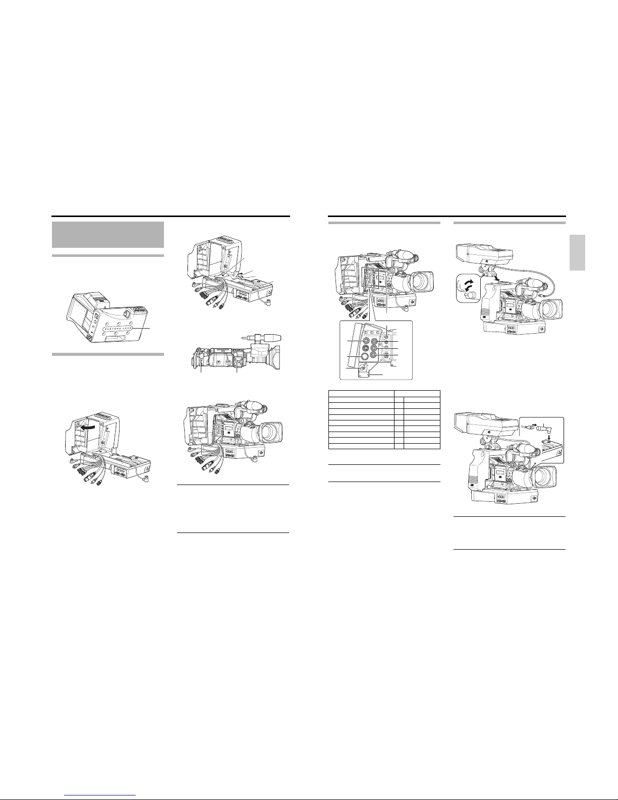
ACHTUNG
• Wenn Sie das Gerät umsetzen, während das Stativ
angebracht ist, kann es sich u. U. loslösen und herunter-
fallen, sollte es plötzlich einem Stoß oder einer Erschüt-
terung ausgesetzt werden. Dabei kann es zu
Verletzungen kommen. Trennen Sie das Gerät vom Sta-
tiv, bevor Sie es an einen anderen Ort bringen.
• Die vordere Sockelhalterung kann einrasten, auch wenn
der Stift an diesem Gerät und die Befestigungslöcher an
der hinteren Sockelhalterung der Kamera nicht miteinan-
der verbunden sind. Überzeugen Sie sich nach der Mon-
tage, dass die Kamera ordnungsgemäß angebracht
wurde. Sollte die Kamera nicht ordnungsgemäß ange-
bracht sein, kann sie herunterfallen und Verletzungen
oder Unfälle verursachen.
• Wenn Sie das Gerät mit ange-
brachter Kamera transportieren,
halten Sie die Unterseite dieses
Geräts fest. Falls beim Transport
der Kameragriff angefasst wird,
kann sich der Aufsatz lösen, und
dieses Gerät fällt möglicherweise
herunter und verursacht Verletzun-
gen oder Unfälle.
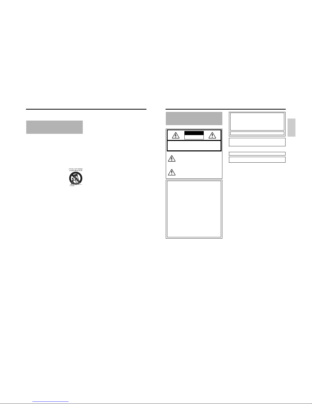
WARNUNG:
UM DAS RISIKO VON BRÄNDEN UND
ELEKTRISCHEN SCHLÄGEN ZU VERRIN-
GERN, SETZEN SIE DIESES GERÄT
KEINEM REGEN UND KEINER FEUCHTIG-
KEIT AUS.
Dieses Gerät darf nur mit 12 V Gleichstrom betrieben
werden.
ACHTUNG:
Um elektrische Schläge und Brände zu verhindern,
verwenden Sie KEINE andere Stromquelle.
ACHTUNG:
Um elektrische Schläge zu vermeiden, öffnen Sie nicht das
Gehäuse. Im Inneren befinden sich keine Teile, die vom Benutzer
gewartet werden können. Überlassen Sie sämtliche Wartungsar-
beiten qualifiziertem Wartungspersonal.
Hinweis:
Das Leistungsschild (Seriennummernschild) befindet sich an die-
sem Gerät.
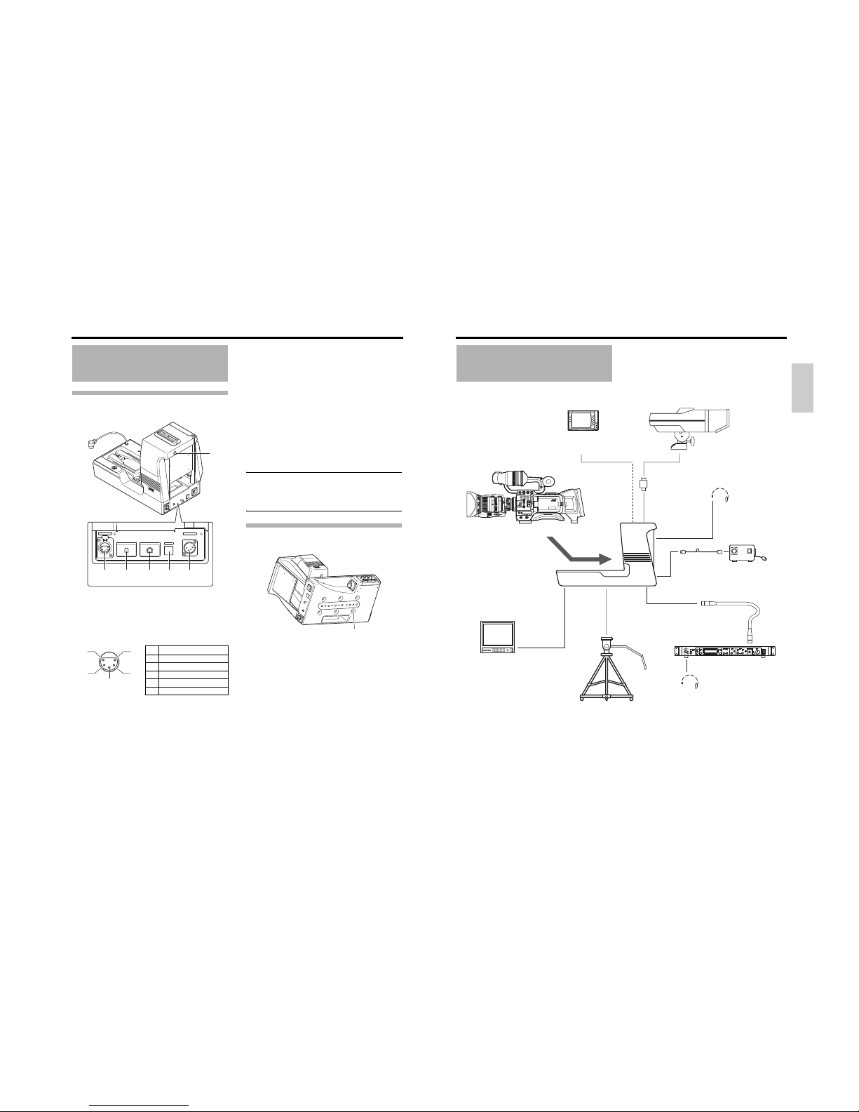
Anschluss Kabel Länge
RM Spezialkabel 10 Meter
PROMPTER OUTPUT Koaxialkabel 5 Meter
DC INPUT Spezialkabel 5 Meter
TALLY OUTPUT Spezialkabel 5 Meter
TALLY INPUT Spezialkabel 5 Meter
INTERCOM Abgeschirmtes Kabel 1,5 Meter
VF OUTPUT (BNC) Koaxialkabel 5 Meter
VF OUTPUT (20-polig) Abgeschirmtes Kabel 0,4 Meter
Sehr geehrter Kunde,
dieses Gerät erfüllt die geltenden europäischen Richtlinien und
Normen in Bezug auf elektromagnetische Kompatibilität und
Stromschutzvorschriften.
Victor Company of Japan, Limited wird in Europa vertreten durch:
JVC Technology Centre Europe GmbH
Postfach 10 05 52
61145 Friedberg
Deutschland
Hinweis:
Dieses Symbol ist nur in der Europäi-
schen Union gültig.
19
Deutsch
Wir bedanken uns für den Kauf dieses Produkts.
(Diese Bedienungsanleitung gilt für folgendes Modell: KA-
HD250U.)
Bevor Sie dieses Gerät verwenden, lesen Sie sorgfältig die
Bedienungsanleitung durch, um eine optimale Leistung
sicherzustellen.
Besondere Merkmale
Ausstattung mit einem analogen
26P-Kameraanschluss
Schließen Sie die Fernsteuereinheit RM-P210 (gesondert
erhältlich) an, um dieses Gerät aus einer Entfernung von bis
zu 100 m zu steuern. In diesem Fall liefert die Fernsteuerein-
heit den Strom für die Kamera, weswegen keine gesonderte
Stromversorgung an die Kamera angeschlossen werden
muss.
Ausstattung mit Multi-System-
Ausgabe
Gibt Composite-Signale sowie RGB-Component-, Y/PB/PR-
Component- oder Y/C-Trennsignale vom 26P-Kameraan-
schluss aus. (Wählbar über den Menüschalter.)
Ausstattung mit einem Intercom-
Anschluss
Verwenden Sie ein Headset, um mit dem Bediener der Fern-
steuereinheit zu kommunizieren. (nur dynamisch)
Ausstattung mit einem Prompter-
Ausgangsanschluss
Gibt Prompter-Videosignale von der Fernsteuereinheit als
Composite-Signale aus.
4-Zoll-Sucher VF-P400 mit einem
Umwandlungsstecker kompatibel
Ausstattung mit Component-
Anschlüssen für einen externen
Monitor (3 × BNC)
INHALTSVERZEICHNIS
EINFÜHRUNG
Besondere Merkmale . . . . . . . . . . . . . . . . . . . . . . . . . . . . .19
Vorsichtsmaßnahmen für die Bedienung . . . . . . . . . . . . . .20
Hinweise zu Genlock-Signal und Anpassung der
Systemphase. . . . . . . . . . . . . . . . . . . . . . . . . . . . . .20
Bedienungselemente, Anzeigen und Anschlüsse . . . . . . .21
Vorderseite . . . . . . . . . . . . . . . . . . . . . . . . . . . . . . . . . .21
Rückseite . . . . . . . . . . . . . . . . . . . . . . . . . . . . . . . . . . .22
Unterseite . . . . . . . . . . . . . . . . . . . . . . . . . . . . . . . . . . .22
VORBEREITUNGEN
Grundsystem . . . . . . . . . . . . . . . . . . . . . . . . . . . . . . . . . . .23
Installation . . . . . . . . . . . . . . . . . . . . . . . . . . . . . . . . . . . . .24
Anbringen an einem Stativ . . . . . . . . . . . . . . . . . . . . . .24
Anbringen der Kamera . . . . . . . . . . . . . . . . . . . . . . . . .24
Anschließen von Kabeln . . . . . . . . . . . . . . . . . . . . . . . .25
Anschließen des Suchers (VF-P400) . . . . . . . . . . . . . .25
Ausgegebene Signale bei Anschluss des Suchers. . . .26
Anschließen an die Fernsteuereinheit RM-P210 . . . . . . . .26
Anschlussverbindung . . . . . . . . . . . . . . . . . . . . . . . . . .26
Einstellung des Menübildschirms . . . . . . . . . . . . . . . . .27
Schaltereinstellung . . . . . . . . . . . . . . . . . . . . . . . . . . . .27
Ablauf . . . . . . . . . . . . . . . . . . . . . . . . . . . . . . . . . . . . . .27
Hinweise zum Bedienen des RM-P210 . . . . . . . . . . . . . . .28
SONSTIGES
Technische Daten . . . . . . . . . . . . . . . . . . . . . . . . . . . . . . .29
Abmessungen. . . . . . . . . . . . . . . . . . . . . . . . . . . . . . . .29