manuals.online logo
Brands
  1. Home
  2. •
  3. Brands
  4. •
  5. JVC
  6. •
  7. Car Receiver
  8. •
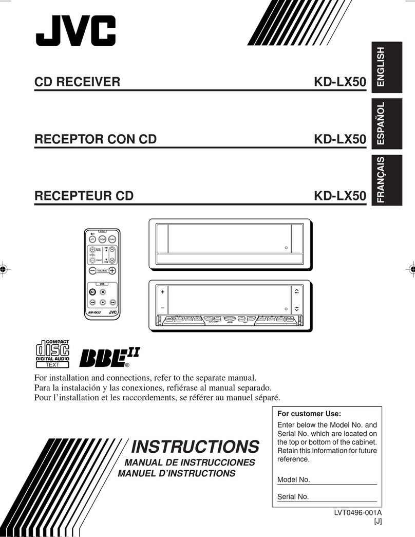
  9. JVC KS-FX201 User manual

JVC KS-FX201 User manual

Other manuals for KS-FX201

1

Other JVC Car Receiver manuals

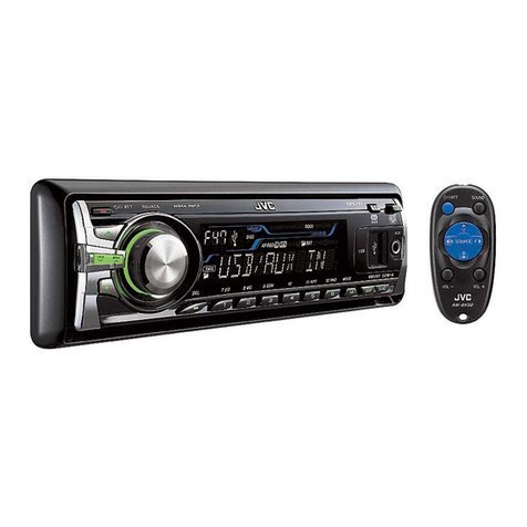
JVC KS-FX850R User manual

JVC

JVC KS-FX850R User manual

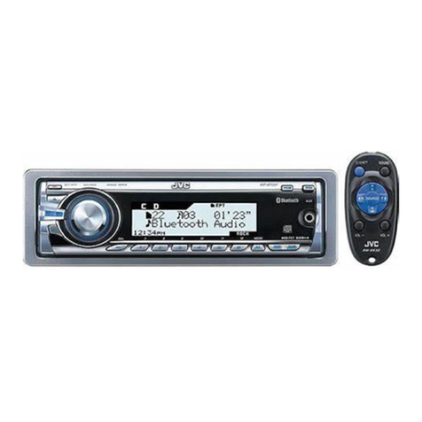
JVC KS-FX611 User manual

JVC

JVC KS-FX611 User manual

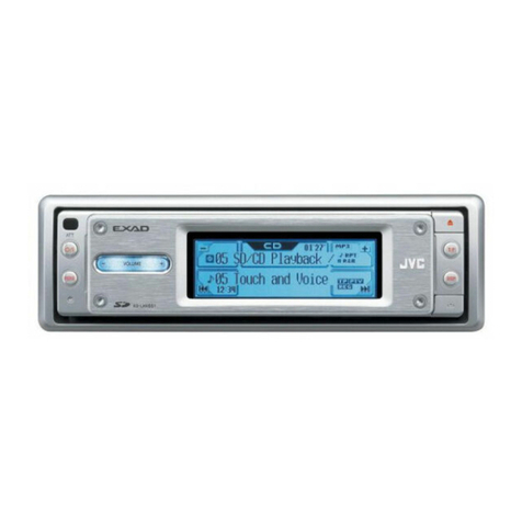
JVC KW-SD70BT User manual

JVC

JVC KW-SD70BT User manual

JVC LVT1134-001A User manual

JVC

JVC LVT1134-001A User manual

JVC KD-G521 User manual

JVC

JVC KD-G521 User manual

JVC KD-DV5301 Guide

JVC

JVC KD-DV5301 Guide

JVC KD-G547 User manual

JVC

JVC KD-G547 User manual

JVC KD-AVX1 User manual

JVC

JVC KD-AVX1 User manual

JVC KD-R530 User manual

JVC

JVC KD-R530 User manual

JVC GET0626-001A User manual

JVC

JVC GET0626-001A User manual

JVC KD-SX780 User manual

JVC

JVC KD-SX780 User manual

JVC KD-G369 User manual

JVC

JVC KD-G369 User manual

JVC KD-G510 User manual

JVC

JVC KD-G510 User manual

JVC CD Receiver KD-SHX701 User manual

JVC

JVC CD Receiver KD-SHX701 User manual

JVC KD-G110 User manual

JVC

JVC KD-G110 User manual

JVC KS-FX480 User manual

JVC

JVC KS-FX480 User manual

JVC KD-AR390 User manual

JVC

JVC KD-AR390 User manual

JVC KD-S30 User manual

JVC

JVC KD-S30 User manual

JVC KS-T707 User manual

JVC

JVC KS-T707 User manual

JVC KW-XC777 - Radio / CD Mounting instructions

JVC

JVC KW-XC777 - Radio / CD Mounting instructions

JVC KS-RT650R User manual

JVC

JVC KS-RT650R User manual

JVC KD-PDR51 Quick start guide

JVC

JVC KD-PDR51 Quick start guide

JVC XG700 KW-XG700 User manual

JVC

JVC XG700 KW-XG700 User manual

JVC KD-G534 User manual

JVC

JVC KD-G534 User manual

Popular Car Receiver manuals by other brands

Linear Series LS5050 Operation and installation manual

Linear Series

Linear Series LS5050 Operation and installation manual

Kenwood KRC-160 instruction manual

Kenwood

Kenwood KRC-160 instruction manual

Sony XR-CA430X Service manual

Sony

Sony XR-CA430X Service manual

T+A Elektroakustik K1 CD-RECEIVER operating instructions

T+A Elektroakustik

T+A Elektroakustik K1 CD-RECEIVER operating instructions

SoundMax SM-CDM1052 instruction manual

SoundMax

SoundMax SM-CDM1052 instruction manual

Xtrons HD107HD user manual

Xtrons

Xtrons HD107HD user manual

Mopar RB3 manual

Mopar

Mopar RB3 manual

Clarion ADDZEST DMZ615 owner's manual

Clarion

Clarion ADDZEST DMZ615 owner's manual

Sony XAV-601BT Specifications

Sony

Sony XAV-601BT Specifications

PIE GM12-POD/S Operation manual

PIE

PIE GM12-POD/S Operation manual

Hyundai H-910H instruction manual

Hyundai

Hyundai H-910H instruction manual

Sony XR-C6100 Service manual

Sony

Sony XR-C6100 Service manual

Sony CDX-L600X - Fm/am Compact Disc Player Installation/connections

Sony

Sony CDX-L600X - Fm/am Compact Disc Player Installation/connections

Motorola VWA63 Service manual

Motorola

Motorola VWA63 Service manual

Sound Storm STM93R user manual

Sound Storm

Sound Storm STM93R user manual

Nextar D3201 instruction manual

Nextar

Nextar D3201 instruction manual

Alpine CDE-163BT owner's manual

Alpine

Alpine CDE-163BT owner's manual

Kenwood KDC-X303 quick start guide

Kenwood

Kenwood KDC-X303 quick start guide

manuals.online logo
manuals.online logoBrands
  • About & Mission
  • Contact us
  • Privacy Policy
  • Terms and Conditions

Copyright 2025 Manuals.Online. All Rights Reserved.

SERVICE MANUAL
CASSETTE RECEIVER
No.49589
Jan. 2001
COPYRIGHT 2001 VICTOR COMPANY OF JAPAN, LTD.
KS-FX201
KS-FX201
Area Suffix
U ---- Other Areas
Contents
Safety precaution
Disassembly method
Adjustment method
Description of major ICs
1-2
1-3
1-12
1-16
This service manual is printed on 100% recycled paper.
KS-FX201
1-2
!Burrs formed during molding may be left over on some parts of the chassis. Therefore,
pay attention to such burrs in the case of preforming repair of this system.
Safety precaution
KS-FX201
1-3
Fig. 3
Disassembly Method
Detaching the Front Panel Unit
( See Fig.1 )
Push the Release button in the direction of arrow to
detach the front panel unit.
Removing the Front Chassis
( See Fig. 2 and 3 )
Disengage the four tabs ( a ) in the right and left sides of
unit and pull the front chassis forward to remove it.
Removing the Bottom Cover
( See Fig. 2 to 4 )
1. Removing the front chassis.
2. Turn the unit up side down.
3. Insert the four engagements ( b, c, d, e ) to the
screwdriver .
4. Turn the screwdriver and remove the bottom
cover.
Fig. 2
Fig. 4
Front panel unit
Fig. 1
Push the release button
Front chassis
Bottom cover
Top chassis
Bottom cover
a
a
bc
a
Front chassis d
Bottom cover
Rear panel
e
KS-FX201
1-4
Removing the Heat Sink ( See Fig. 5 )
1. Removing the front chassis.
2. Removing the bottom cover.
3. Remove the three screws ( 1 and 1' ) retaining the
heat sink.
Removing the Main Board Assembly
( See Fig. 5 to 7)
1. Removing the front chassis.
2. Removing the bottom cover.
3. Removing the heat sink.
Attach the heat sink with a screw ( 1' ) on operat-
ing checks.
4. Remove the two screws ( 2 ) retaining the main
board assembly.
5. Remove the six screws ( 3 ) and one screw ( 3' ) retaining
6. Separate the main board assembly and cassette
mechanism assembly.
7. Take out the main board assembly.
Fig. 5
Fig. 6
Fig. 7
( )
the rear panel.
Heat sink
11
1'
2
2
Main board assembly
Rear panel
333'
3
KS-FX201
1-5
Fig. 9
Fig. 11
Fig. 10
Removing the Cassette Mechanism assembly
( See Fig. 8 )
1. Removing the front chassis.
2. Removing the bottom cover.
3. Removing the heat sink.
4. Removing the main board assembly.
5. Remove the four screws ( 4 ) retaining the cassette
mechanism.
6. Separate the top chassis and cassette mechanism.
Fig. 8
Removing the Operation Switch board
( See Fig. 9 to 11)
1. Detaching the front panel unit.
2. Turn the front panel back side down.
3. Remove the four screws ( 5 ) retaining the front
cover.
4. Open the front cover gradually by disengaging the
three engagements ( g ) while pushing the top of
the front cover in the arrow "A" direction, then
disengage the three engagements ( h ) on the both
sides.
5. Place the front panel unit front side down.
6. Disengage the three engagements ( i ) on the
bottom to separate the front cover from the front
panel.
(Be careful not to lose the button springs.)
Front side
Cassette mechanism
Top chassis
44
44
gg
g
Front cover
A
5
5
5
5
h
h
h
Front cover
Front panel
iii
Operation switch board
KS-FX201
1-6
Fig. 14
Removing the Head Amplifier Board
( See Fig. 12 )
1. Removing the front chassis.
2. Removing the bottom cover.
3. Removing the heat sink.
4. Removing the main board assembly.
5. Removing the cassette mechanism.
6. Remove the screw ( 6 ) retaining the head ampli-
fier board.
7. Shift the two inter rocking sections ( j ) securing
the head amplifier board in the direction shown by
the arrow "B" to remove the printed circuit board.
8. From the connector CJ901 on the head amplifier
board from connector wire out going to the head
relay board.
Removing the Chassis Assembly
( See Fig. 13 and 14 )
1. Removing the front chassis.
2. Removing the bottom cover.
3. Removing the heat sink.
4. Removing the main board assembly.
5. Removing the cassette mechanism.
6. Removing the head amplifier board.
7. Turn the left side to cassette mechanism.
8. Remove the screw ( 7 ) retaining the relay board.
9. Shift the one inter rocking sections ( k ) securing
the relay board in the direction shown by the
arrow "C" to remove the printed circuit board.
10. Turn the back side down, remove the four screws
( 8 ) retaining the chassis assembly.
Fig. 12
Fig. 13
B
To head relay board
CJ901
Head amplifier board
j
j
6
Relay board
k
C
7
Chassis assembly
8
8
8
8
KS-FX201
1-7
Prior to performing the following procedures, remove
the head amplifier board, the relay board and the
mechanism bracket.
<Cassette mechanism assembly>
Unsolder the three wires aon the direction switch
board.
Remove the one screw Aattaching the direction
switch board.
1.
2.
Removing the direction switch board
(See Fig.1)
Remove the screw Battaching the FF / REW lever
assembly on the back of the cassette mechanism
assembly.
Remove the screw Con the upper side of the FF /
REW lever assembly.
Lift and pull forward the FF / REW lever assembly to
disengage the joints b, c, dand e.
1.
2.
3.
Removing the FF / REW lever assembly
(See Fig.1)
Reattach the FF / REW lever assembly to the joint c
on the back of the chassis.
Reattach the pinch-roller shaft e, the change lever d
and the return link eto the chassis.
1.
2.
Reattaching the FF / REW lever assembly
(See Fig.1)
C
FF / REW lever assembly
Joint c
Joint b
B
A
Direction switch board
Joint d
Joint e
Solding a
Fig.1
KS-FX201
1-8
Prior to performing the following procedure, remove
the direction switch board and the FF / REW lever
assembly.
Remove the screw Dattaching the playback head.
Remove the C washer and pull out the FF roller.
Remove the S support plate, the A arm spring (a)
and (b), the playback head.
1.
2.
3.
Removing the playback head (See Fig.2)
The A arm spring (a) differs from the A
arm spring (b).
ATTENTION:
Prior to performing the following procedure, remove
the direction switch board and the FF / REW lever
assembly.
Remove the P arm spring (f) in the pinch-roller (F)
assembly from the chassis.
Remove the P arm spring (r) in the pinch-roller (R)
assembly from the chassis.
Draw out the pinch roller (F) and (R) assembly from
the shaft.
1.
2.
3.
Removing the pinch-roller (R) and (F)
assembly (See Fig.2)
The P arm spring (f) differs from the P
arm spring (r).
ATTENTION:
The pinch roller (F) assembly differs
from the pinch roller (R) assembly.
ATTENTION:
A arm spring (b) A arm spring (a)
Pinch-roller (R) assembly Pinch-roller (F) assembly
Shaft Shaft
S support plate
D
C washer
P arm spring (f)
P arm spring (r)
Remove the P arm spring (f)
from the chassis.
Remove the P arm spring (r)
from the chassis.
Playback head
FF roller
Fig.2
KS-FX201
1-9
Prior to performing the following procedure, remove
the FF / REW lever assembly.
From the rear of the unit, bend the two tabs f
outwards and disengage the two joints gin the
direction of the arrow.
Push the eject lever and remove the cassette holder
from the playback head. Disengage the two joints h
of the cassette hanger / cassette holder and the eject
lever in the direction of the arrow.
Lift the cassette hanger / cassette holder and disengage
the joint iof the return link and the eject lever.
1.
2.
3.
Removing the cassette hanger / cassette
holder (See Fig.3)
Unsolder the two wires jon the motor assembly.
1.
Turn over the cassette mechanism assembly and
remove the main belt and the sub-belt from the
motor pulley.
2.
Remove the two screws Gattaching the motor
assembly.
3.
Removing the motor assembly
(See Fig.5)
To replace the sub-belt, remove the
main belt and the sub-belt from the
motor pulley. Then remove the three
screws Eand one screw F. Replace
with a new sub-belt while lifting the reel
base assembly slightly.
ATTENTION:
Prior to performing the following procedure, remove
the FF / REW lever assembly and the cassette
hanger / cassette holder.
Remove the C washer and pull out reel disc assembly.
1.
Removing the reel disc assembly
(See Fig.4)
Replace with a new C washer when
reattaching.
ATTENTION:
The main belt can now be removed.
ATTENTION:
Cassette holder
Cassette hanger
Return link
Joint i
Eject lever
Joint h
Joint h
Joint g
Joint g Tab f
Tab f
Reel disc assembly
Flywheel (BF)
Flywheel (BR)
E
E
E
F
G
G
Main-belt
Reel base assembly
Sub-belt
Motor assembly
Motor pulley
Solding j
Fig.3
Fig.4
Fig.5
C washer
C washer
Chassis
KS-FX201
1-10
Raise the part kof the reel base assembly slightly
and remove the selector link (B) on the front side of
the cassette mechanism assembly by turning it as
shown in Fig.10.
Remove the three screws Eand the one screw F
on the underside of the cassette mechanism
assembly.
1.
2.
Removing the reel base assembly
(See Fig.5 and 6)
Prior to performing the following procedure, remove
the cassette hanger / cassette holder.
From the upper side of the cassette mechanism
assembly, remove the C washer from each shaft of
the flywheel (BF) and (BR).
Turn over the cassette mechanism assembly and
remove the main belt. Pull out the flywheel (BF) and
(BR) downward respectively.
1.
2.
Removing the Flywheel (BF) and (BR)
assembly (See Fig.4 and 5)
The reel base assembly is not
repairable. Handle with care.
ATTENTION:
Selector link (B).
Inside of the reel base assembly
Reel disc assembly
Flywheel (BF)
Flywheel (BR)
E
E
E
F
G
G
Main-belt
Reel base assembly
Sub-belt
Motor assembly
Motor pulley
Solding j
Fig.4
Fig.5
Fig.6Fig.7
C washer
C washer
Pinch-roller (R) assembly
Turn the selector link (B).
k