1-2 (No.MA401<Rev.001>)
SPECIFICATION
KD-ADV49JC/KD-AVX44JC
Design and specifications are subject to change without notice.
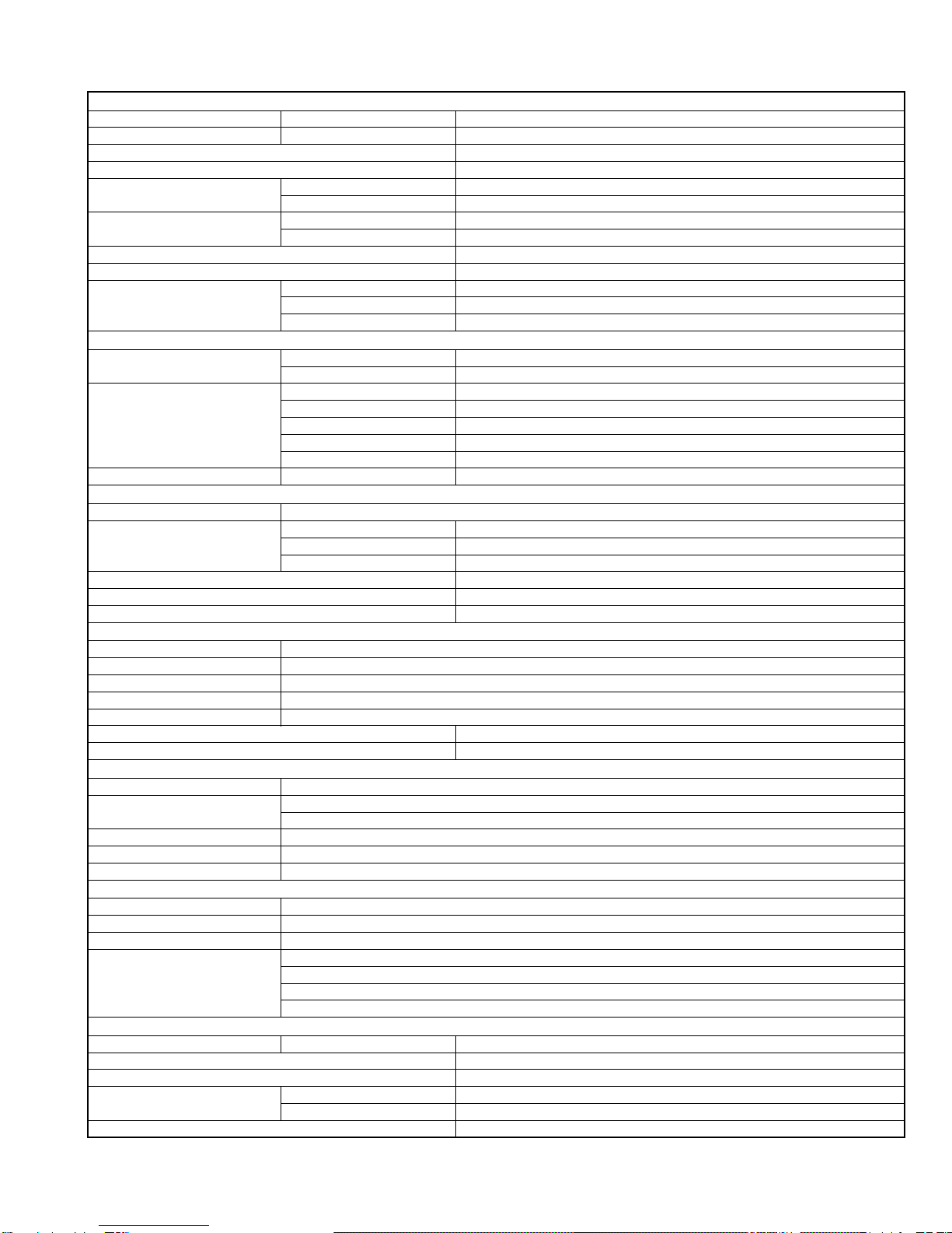
AMPLIFIER
Power Output 20 W RMS ×4 Channels at 4 Ωand < or = 1% THD+N
Signal-to-Noise Ratio 80 dBA (reference 1 W into 4 Ω)
Load Impedance 4 Ω(4 Ωto 8 Ωallowance)
Equalizer Control Range Frequencies
60.0 Hz, 150.0 Hz, 400.0 Hz, 1.0kHz, 2.5kHz, 6.3kHz, 15.0kHz
Level ±10 dB
Audio Output Level LINE OUT (FRONT/ REAR)/
CENTER OUT/ SUBWOOFER OUT
Line-Out Level/Impedance 5.0 V/20 kΩload (full scale)
Output Impedance 1 kΩ
Color System NTSC
Video Output (composite) 1 Vp-p/75 Ω
Other Terminals Input LINE IN, VIDEO IN, USB input terminal, Antenna input
Output 2nd AUDIO OUT, VIDEO OUT
Others CD changer, OE REMOTE
FM/AM TUNER
Frequency Range
FM (with channel interval set to 100 kHz or 200 kHz)
87.5 MHz to 107.9 MHz
FM (with channel interval set to 50 kHz) 87.5 MHz to 108.0 MHz
AM (with channel interval set to 10 kHz) 530 kHz to 1 710 kHz
AM (with channel interval set to 9 kHz) 531 kHz to 1 602 kHz
FM Tuner Usable Sensitivity 11.3 dBf (1.0 µV/75 Ω)
50 dB Quieting Sensitivity 16.3 dBf (1.8 µV/75 Ω)
Alternate Channel Selectivity (400 kHz) 65 dB
Frequency Response 40 Hz to 15 000 Hz
Stereo Separation 35 dB
AM Tuner Sensitivity/Selectivity 20 µV/35 dB
DVD/CD
Signal Detection System Non-contact optical pickup (semiconductor laser)
Frequency Response DVD, fs=48 kHz 16 Hz to 22 000 Hz
DVD, fs=96 kHz 16 Hz to 44 000 Hz
VCD/CD 16 Hz to 20 000 Hz
Dynamic Range 93 dB
Signal-to-Noise Ratio 94 dB
Wow and Flutter Less than measurable limit
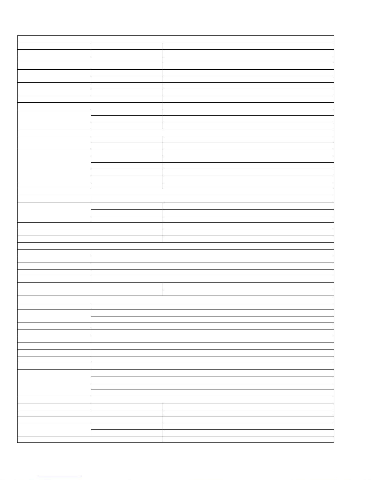
MONITOR
Screen Size 3.5 inch wide liquid crystal display
Number of Pixel 211 200 pixels : 960 (horizontal) ×220 (vertical)
Drive Method TFT (Thin Film Transistor) active matrix format
Color System PAL/NTSC
Aspect Ratio 16:9 (wide)
Allowable Storage Temperature -10°C to + 60°C (14°F to 140°F)
Allowable Operating Temperature 0°C to + 40°C (32°F to 104°F)
USB
USB Standards USB 2.0 Full Speed
Full Speed : Maximum 12 Mbytes
Data Transfer Rate Low Speed : Maximum 1.5 Mbytes
Compatible Device Mass storage class
Compatible File System FAT 32/16/12 BLUETOOTH
Version Bluetooth 1.2 certified
Output Power +4 dBm Max. (Power class 2)
Service Area Within 10 m (10.9 yd)
Profile HFP (Hands-Free Profile) 1.5
OPP (Object Push Profile) 1.1
A2DP (Advanced Audio Distribution Profile) 1.2
AVRCP (Audio/Video Remote Control Profile) 1.3
GENERAL
Power Requirements DC 14.4 V (11 V to 16 V allowance)
Grounding System Negative ground
Allowable Operating Temperature 0°C to +40°C (32°F to 104°F)
Dimensions (W ×H ×D) Installation Size (approx.) 182 mm ×52 mm ×160 mm
(7-3/16” ×2-1/16” ×6-5/16”)
Panel Size (approx.) 188 mm ×58 mm ×12 mm
(7-7/16”×2-5/16” ×1/2”)
Mass (approx.) 2.2 kg (4.9 lbs) (excluding accessories)