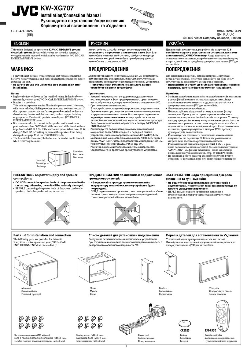
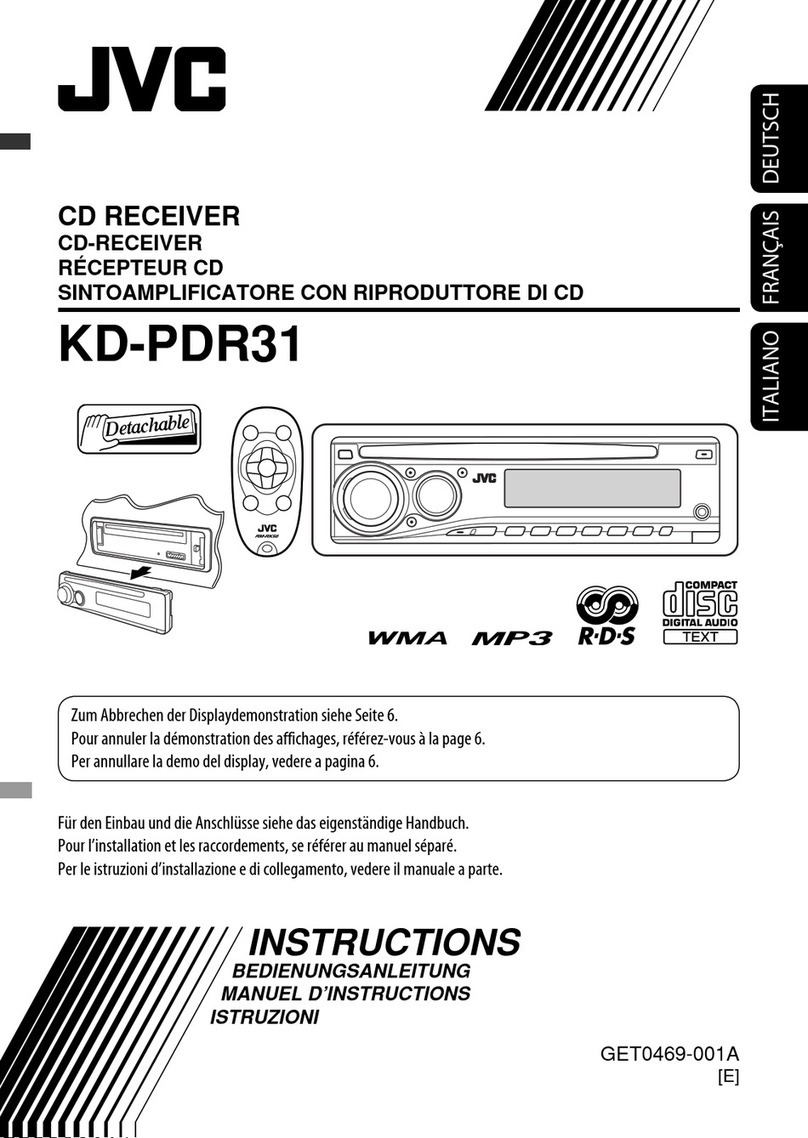
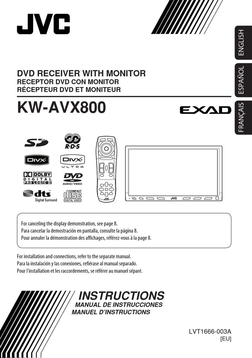
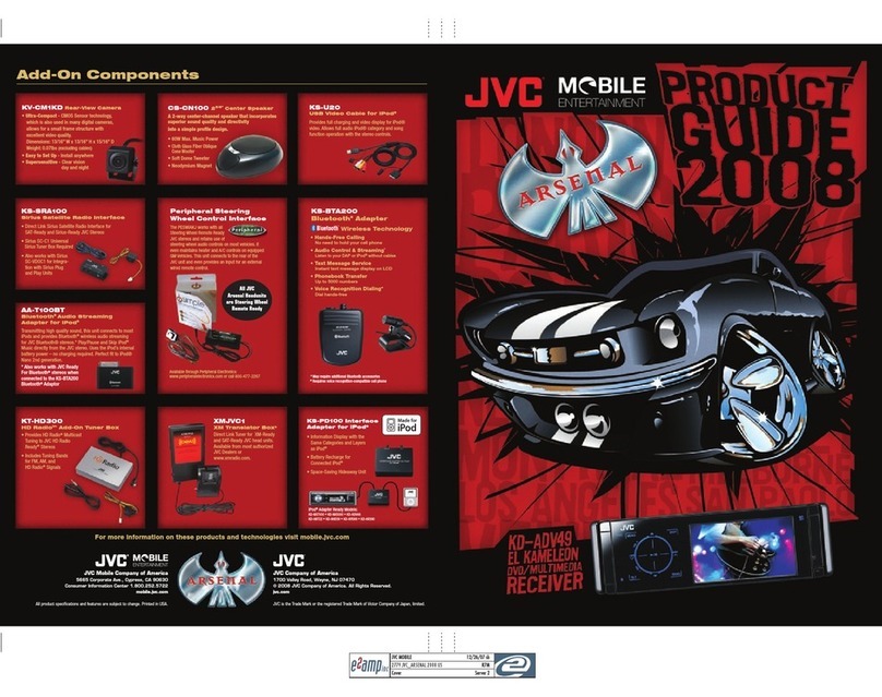
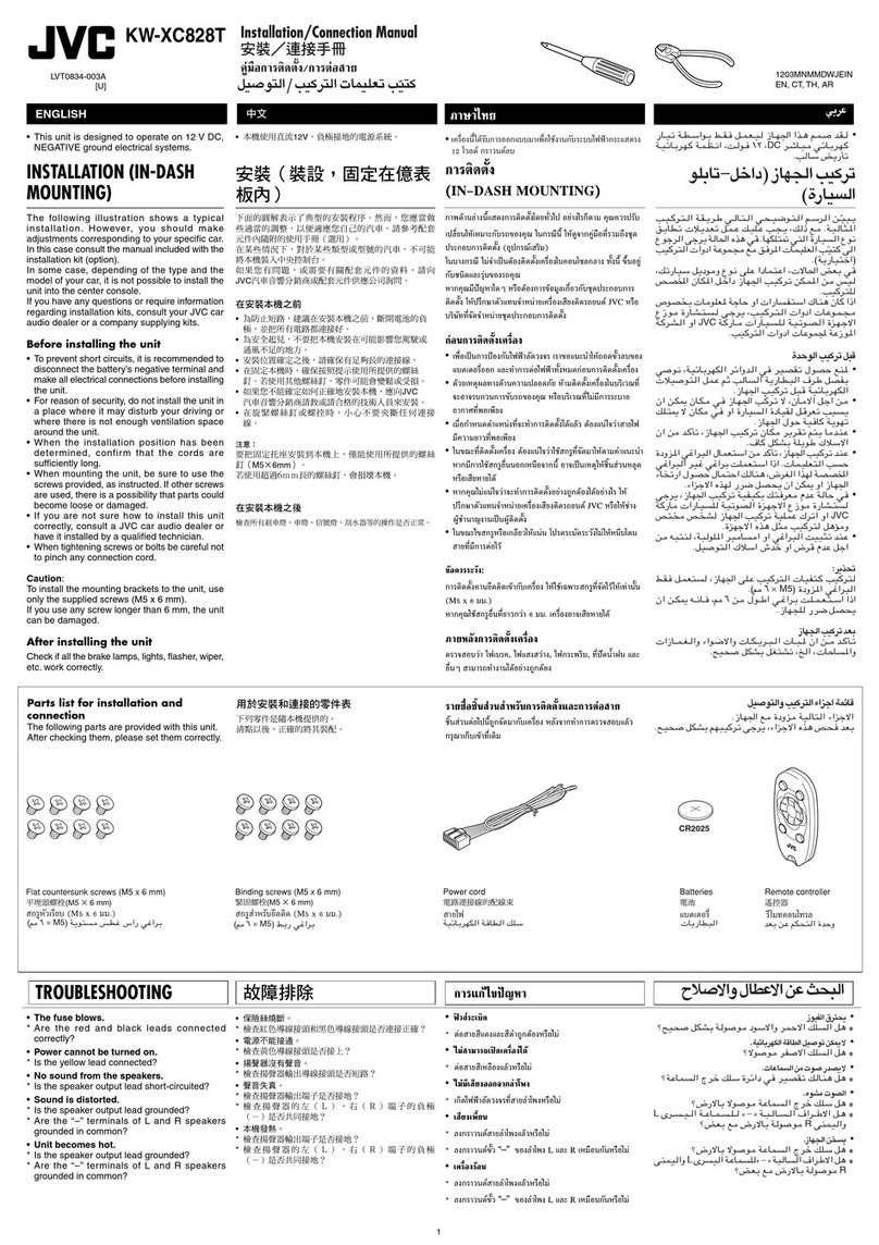
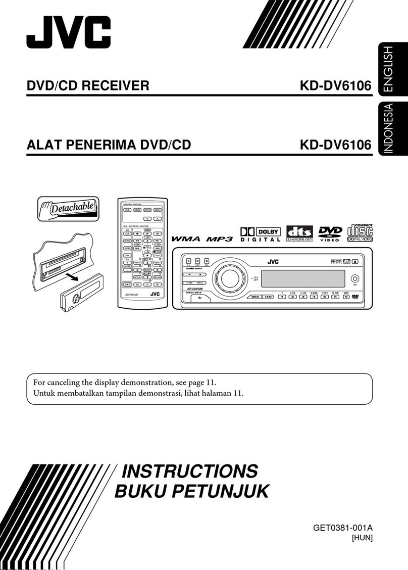
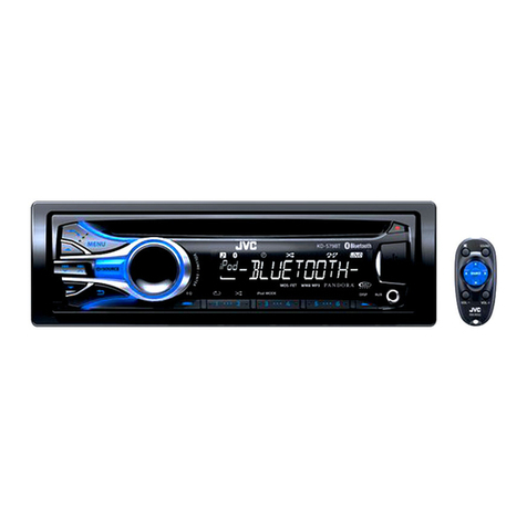
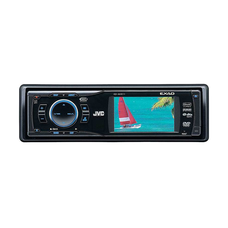
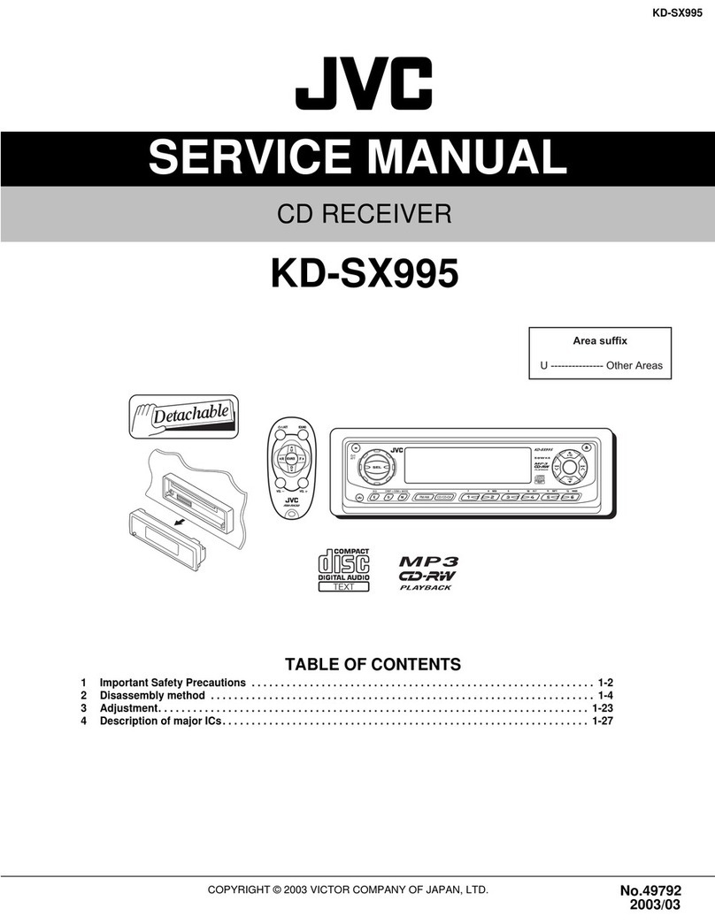
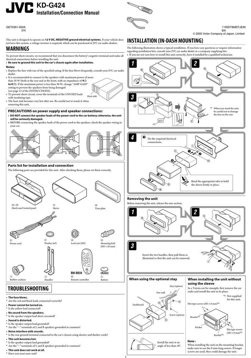
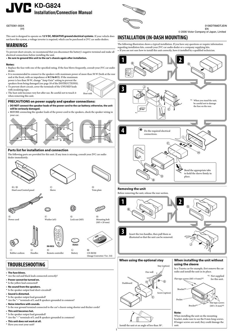
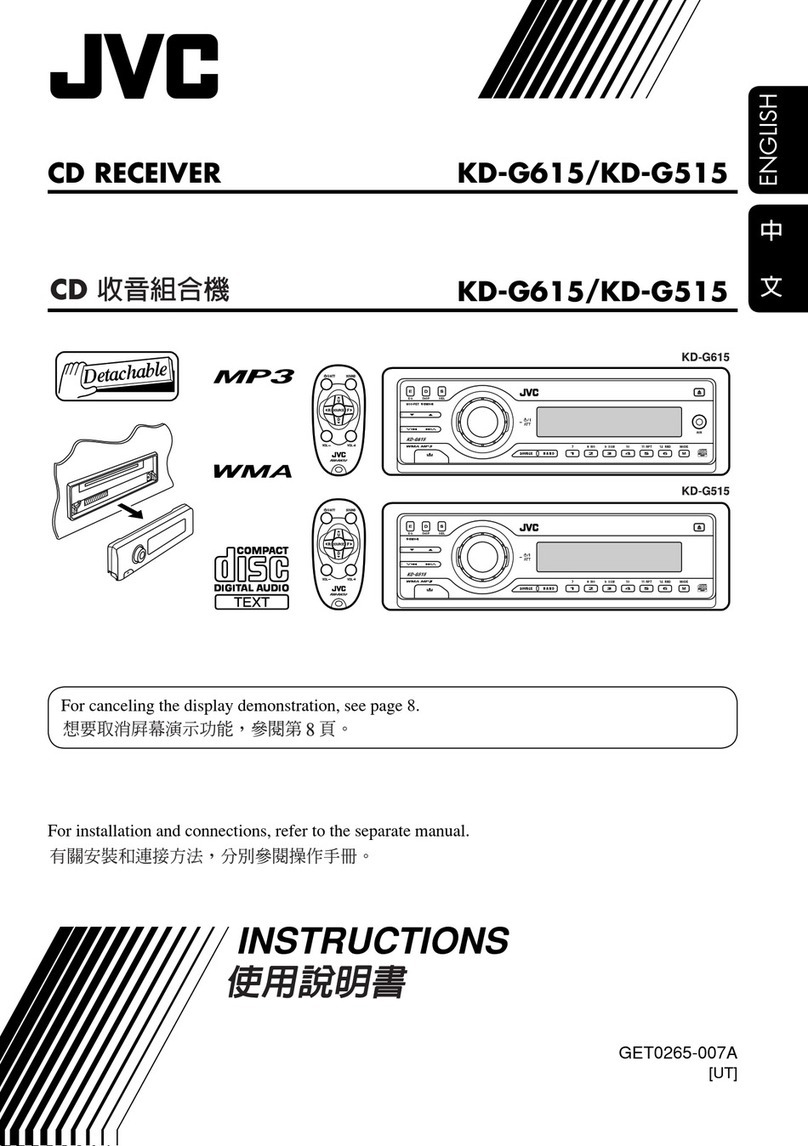
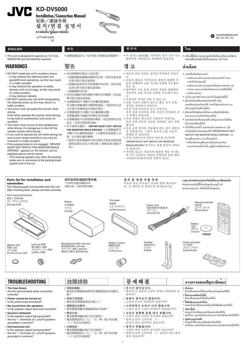
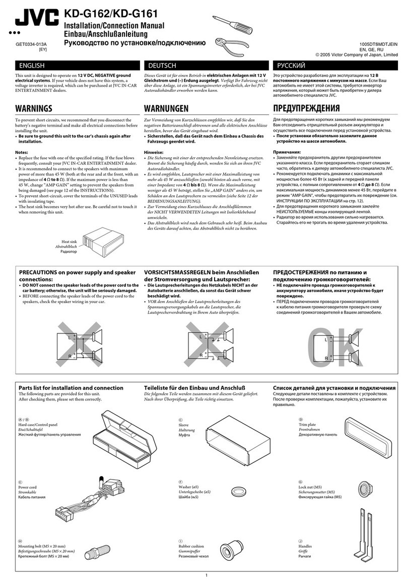
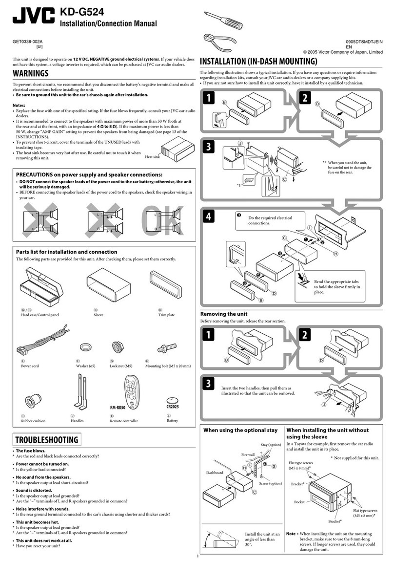
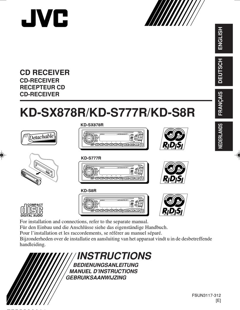
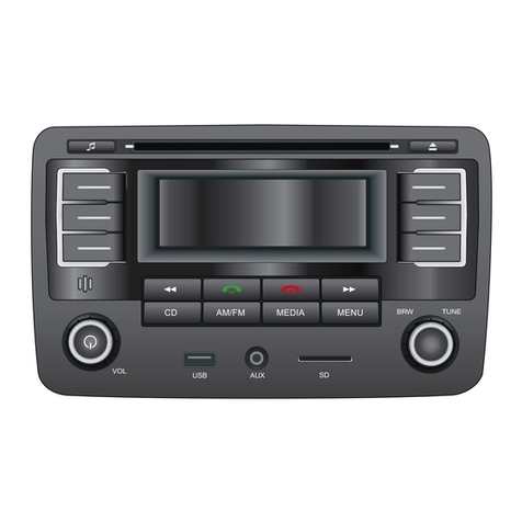
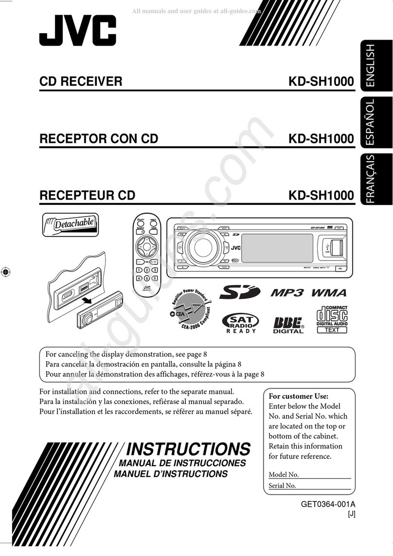
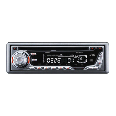
JVC KD-S580 User manual

SERVICE MANUAL
CD RECEIVER
No.49666B
Aug. 2002
COPYRIGHT 2002 VICTOR COMPANY OF JAPAN, LTD.
KD-S580
KD-S580
Area Suffix
J ------ Northern America
Contents
Safety precaution
Preventing static electricity
Disassembly method
Adjustment method
The new CD mechanism is installed in this set.
How to distinguish the new CD mechanism is displayed in a nameplate central upper row as "J2".
1-2
1-3
1-5
1-19
Flow of functional
operation unit TOC read
Maintenance of laser pickup
Replacement of laser pickup
Description of major ICs
1-20
1-22
1-22
1-23
FM
CD
AM
SSM
DIRECT TRACK ACCESS
MO RPT RND
MODE SCM

1-2
KD-S580
!Burrs formed during molding may be left over on some parts of the chassis. Therefore,
pay attention to such burrs in the case of preforming repair of this system.
Safety precaution
!Please use enough caution not to see the beam directly or touch it in case of an
adjustment or operation check.

1-3
KD-S580
Front bracket
CD mechanism
control board
Damper bracket
CD mechanism ass’y
FD screw
Feed motor ass’y
FD gear Pickup unit
Preventing static electricity
1.Grounding to prevent damage by static electricity
Electrostatic discharge (ESD), which occurs when static electricity stored in the body, fabric, etc. is discharged,
can destroy the laser diode in the traverse unit (optical pickup). Take care to prevent this when performing repairs.
2.About the earth processing for the destruction prevention by static electricity
Static electricity in the work area can destroy the optical pickup (laser diode) in devices such as CD players.
Be careful to use proper grounding in the area where repairs are being performed.
2-1 Ground the workbench
Ground the workbench by laying conductive material (such as a conductive sheet) or an iron plate over
it before placing the traverse unit (optical pickup) on it.
2-2 Ground yourself
Use an anti-static wrist strap to release any static electricity built up in your body.
3. Handling the optical pickup
1. In order to maintain quality during transport and before installation, both sides of the laser diode on the
replacement optical pickup are shorted. After replacement, return the shorted parts to their original condition.
(Refer to the text.)
2. Do not use a tester to check the condition of the laser diode in the optical pickup.The tester's internal power
source can easily destroy the laser diode.
4.Handling the traverse unit (optical pickup)
1. Do not subject the traverse unit (optical pickup) to strong shocks, as it is a sensitive, complex unit.
2. Cut off the shorted part of the flexible cable using nippers, etc. after replacing the optical pickup. For specific
details, refer to the replacement procedure in the text.Remove the anti-static pin when replacing the traverse
unit. Be careful not to take too long a time when attaching it to the connector.
3. Handle the flexible cable carefully as it may break when subjected to strong force.
4. It is not possible to adjust the semi-fixed resistor that adjusts the laser power. Do not turn it
Conductive material
(conductive sheet) or iron plate
(caption)
Anti-static wrist strap
Soldering
Attention when traverse unit is decomposed
1.Solder is put up before the card wire is removed from connector on
the CD substrate as shown in Figure.
(When the wire is removed without putting up solder, the CD pick-up
assembly might destroy.)
2.Please remove solder after connecting the card wire with
when you install picking up in the substrate.
*Please refer to "Disassembly method" in the text for pick-up and how to
detach the substrate.
1-4
KD-S580
< MEMO >

1-5
KD-S580
Push the release bottom in the lower right part of the
front panel and remove the front panel assembly in
the direction of the arrow.
1.
Removing the front panel assembly
(See Fig.1)
Prior to performing the following procedure, remove
the front panel assembly.
Release the two joints a and the two joints bon
both sides of the body using a screwdriver, and
remove the front chassis assembly forward.
1.
Removing the front chassis assembly
(See Fig.2, 3)
Remove the screw A and the two screws Bon the
left side of the body.
1.
Removing the heat sink (See Fig.4)
Disassembly
<Main body>
Fig.1
Fig.2
Fig.3
Front panel assembly Release bottom
Front chassis assembly
Joint b
Joint b
Heat sink
Fig.4
AB
B
Joint a
Joint a

1-6
KD-S580
Prior to performing the following procedure, remove
the front panel assembly, the front chassis assembly
and the heat sink.
Turn over the body and release the two joints cthe
two joints dand the joint e.
1.
Removing the bottom cover
(See Fig.5, 6)
Do not damage the board when
releasing the joint eusing a screwdriver.
(See Fig.5, 6)
CAUTION:
Prior to performing the following procedure, remove
the front panel assembly, the front chassis, the heat
sink and the bottom cover.
Remove the three screws C, the four screws D
and the screw Eon the back of the body. Remove
the rear panel.
1.
Removing the rear panel (See Fig.7)
Prior to performing the following procedure, remove
the front panel assembly, the front chassis, the heat
sink, the rear panel and the bottom cover.
Remove the two screws Fattaching the main
board assembly. Disconnect connector CN501 and
remove the main board assembly.
1.
Removing the main board assembly
(See Fig.8)
CD
E
C
D
D C
Rear panel
Fig.7
Fig.8
Main board assemblyCN501
FF
Fig.5
Fig.6
Bottom cover
Bottom cover
Joint c
Joint c
Joint d
Joint d
Joint e
Joint e

1-7
KD-S580
Prior to performing the following the procedure,
remove the front panel assembly, the front chassis,
the heat sink, the bottom cover, the rear panel and
the main board assembly.
Remove the three screws G.
1.
Removing the CD mechanism assembly
(See Fig.9)
Prior to performing the following procedure, remove
the front panel assembly.
Remove the four screws Hon the back of the front
panel assembly.
Release the twelve joints f.
Pull out the LCD key operation board.
1.
2.
3.
RemovingThe LCD key operation board
(See Fig.10~12)
Fig.9
CD mechanism assembly
GFront chassis
G
G
HH
HH
Fig.10
Fig.11
Fig.12
LCD operation board
Joint f
Joint f
Joint f
Joint f
Joint f
Front panel
Rear cover

1-8
KD-S580
Remove the two screws Aon each side of the body.
Lift the front side of the top cover and move the
cover backward to release the two joints a.
1.
2.
Removing the top cover (See Fig.1 and 2)
Remove the screw Bfixing the connector board.
Solder the short-circuit point on the connector board.
Disconnect the flexible wire from the pickup.
Move the connector board in the direction of the
arrow to release the two joints b.
Unsolder the wire on the connector board if
necessary.
1.
2.
3.
4.
Removing the connector board
(See Fig.3 to 5)
Before disconnecting the flexible wire
from the pickup, solder the short-circuit
point on the pickup. No observance of
this instruction may cause damage of
the pickup.
CAUTION:
Unsolder the short-circuit point after
reassembling.
CAUTION:
Fig.1
Fig.2
Fig.3
Fig.4
Fig.5
A
A
A
B
B
Joints a
Joints a
Top cover
Top cover
Connector board
DET switch
Pickup
Pickup
Short-circuit
Joints b
Short-circuit point
(Soldering)
Flexible wire
Flexible wire
Connector board
Frame
< CD mechanism section >

1-9
KD-S580
Extend the two tabs cof the feed sw. holder and pull
out the switch.
Unsolder the DET switch wire if necessary.
1.
2.
Removing the DET switch
(See Fig.3 and 6)
Prior to performing the following procedure, remove
the top cover and the connector board.
Remove the two suspension springs (L) and (R)
attaching the chassis unit to the frame.
1.
Removing the chassis unit
(See Fig.7 and 8)
The shape of the suspension spring (L)
and (R) are different. Handle them with
care.
CAUTION:
When reassembling, make sure that the
three shafts on the underside of the
chassis unit are inserted to the dampers
certainly.
CAUTION:
Fig.3
Fig.6
Fig.8
Fig.7
B
Connector board
DET switch
DET switch
Pickup
Short-circuit
Joints b
Tab c
Feed sw. holder
Tab c
Suspension spring (L)
Suspension spring (R)
Chassis unit
Chassis unit
Frame
Frame
Shafts
Shaft
Damper
Damper
Damper

1-10
KD-S580
Prior to performing the following procedure, remove
the top cover, the connector board and the chassis
unit.
Remove the screw Cand move the loading / feed
motor assembly in the direction of the arrow to
remove it from the chassis rivet assembly.
Disconnect the wire from the loading / feed motor
assembly if necessary.
1.
2.
Removing the loading / feed motor
assembly (See Fig.11 and 12)
Prior to performing the following procedure, remove
the top cover.
Remove the clamper arm spring.
Move the clamper assembly in the direction of the
arrow to release the two joints d.
1.
2.
Removing the clamper assembly
(See Fig.9 and 10)
When reassembling, connect the wire
from the loading / feed motor assembly
to the flame as shown in Fig.11.
CAUTION:
Fig.9
Fig.10
Fig.12Fig.11
Clamper arm
spring
Clamper arm spring
Chassis rivet
assembly
Joint d
Joint d Clamper assembly
Clamper assembly
Joint d
Joint d
Chassis rivet assembly
Loading / feed motor assembly
C

1-11
KD-S580
Reattach the feed rack to the pickup unit using the
screw F.
Reattach the feed sw. holder to the feed rack while
setting the joint tab gto the slot of the feed rack and
setting the part fof the feed rack to the switch of the
feed sw. holder correctly.
As the feed sw. holder is temporarily attached to the
pickup unit, set to the gear of the joint gand to the
bending part of the chassis (joint h) at a time.
1.
2.
3.
Reattach the feed sw. holder using the screw E.
Reattach the shaft to the pickup unit. Reattach the
pu. shaft holder to the shaft using the screw D.
4.
5.
Reattaching the pickup unit
(See Fig.13 to 16)
Prior to performing the following procedure, remove
the top cover, the connector board and the chassis
unit.
Remove the screw Dand pull out the pu. shaft
holder from the shaft.
Remove the screw Eattaching the feed sw. holder.
Move the part eof the pickup unit upward with the
shaft and the feed sw. holder, then release the joint f
of the feed sw. holder in the direction of the arrow.
The joint gof the pickup unit and the feed rack is
released, and the feed sw. holder comes off.
Remove the shaft from the pickup unit.
Remove the screw Fattaching the feed rack to the
pickup unit.
1.
2.
3.
4.
5.
Removing the pickup unit
(See Fig.13 to 17)
Make sure that the part ion the underside
of the feed rack is certainly inserted to the
slot jof the change lock lever.
CAUTION:
Fig.13
Fig.14
Fig.15
Fig.17
Fig.16
Feed sw. holder
Feed sw. holder
Feed sw. holder
E
D
D
E
F
Joint f
Joint f
Joint f
Joint g
Joint f
Joint e
Joint e
Pickup unit
Pu. shaft holder
Pu. shaft holder
Shaft
Shaft
Feed rack
Feed rack
Pickup unit
Pickup unit
Feed sw. holder
Pickup unit
Feed rack
Pickup unit
Joint h
Part i
Slot j
Joint g

1-12
KD-S580
Prior to performing the following procedure, remove
the top cover, the connector board, the chassis unit,
and the clamper assembly.
Remove the screw H.
Move the top plate assembly in the direction of the
arrow to release the two joints p.
Unsolder the wire marked qif necessary.
1.
2.
3.
Removing the top plate assembly
(See Fig.20)
Prior to performing the following procedure, remove
the top cover, the connector board and the clamper
unit.
Turn the trigger arm in the direction of the arrow to
release the joint kand pull out upward.
1.
Removing the trigger arm
(See Fig.18 and 19)
When reassembling, insert the part land
mof the trigger arm into the part nand
oat the slot of the chassis rivet
assembly respectively and join the joint
kat a time.
CAUTION:
Fig.18
Fig.19
Fig.20
Joint k
Trigger arm
Trigger arm
Chassis rivet assembly
Part n
Part l
Part m
Part o
Top plate assembly
Joints p
q
H

1-13
KD-S580
Reattach the select lock arm spring to the top plate
and set the shorter end of the select lock arm spring
to the hook uon the top plate.
Set the other longer end of the select lock arm spring
to the boss von the underside of the select lock arm,
and join the select lock arm to the slots (joint t). Turn
the select lock arm as shown in the figure.
Reattach the select arm (L) while setting the part rto
the first peak of the link plate gear, and join the joint
s.
1.
2.
3.
Reassembling the select arm (L) / select
lock arm (See Fig.23 to 25)
Prior to performing the following procedure, remove
the top plate assembly.
Bring up the select arm (L) to release from the link
plate (joint r) and turn in the direction of the arrow to
release the joint s.
Unsolder the wire of the select arm (L) marked qif
necessary.
Turn the select lock arm in the direction of the arrow
to release the two joints t.
The select lock arm spring comes off the select lock
arm at the same time.
1.
2.
3.
Removing the select arm (L) / select lock
arm (See Fig.21 and 22)
When reattaching the select arm (L),
check if the points wand xare correctly
fitted and if each part operates properly.
CAUTION:
Reverse the above removing procedure.
REFERENCE:
Fig.21
Fig.22
Fig.23
Fig.25
Fig.24
Top plate
Top plate
Select arm (L)
Select lock arm
Select lock arm Select lock
arm spring
Select lock arm
Select lock arm
Select
lock arm
Joint r
Link plate
Link plate
Select arm (R)
Joint s q
Link plate spring
Joint b'
Joints t
Hook u
Hook u
Boss v
Select lock arm spring
Joint t
Joint t
Link plate Joint r
Point x
Select arm (L)
Select arm (R) Link plate spring
Joint r
Joint s

1-14
KD-S580
Reattach the link plate spring.
Reattach the link plate to the link plate spring while
joining them at joint b’.
Reattach the joint yof the select arm (R) to the first
peak of the link plate while joining the two joints z
with the slots. Then turn the select arm (R) as shown
in the figure. The top plate is joined to the joint a’.
1.
2.
3.
Reattaching the Select arm (R) / link
plate (See Fig.25 and 26)
Prior to performing the following procedure, remove
the top plate assembly.
Bring up the select arm (R) to release from the link
plate (joint y) and turn as shown in the figure to
release the two joints zand joint a’.
Move the link plate in the direction of the arrow to
release the joint b’. Remove the link plate spring at
the same time.
1.
2.
Removing the select arm (R) / link plate
(See Fig.21 and 22)
When reattaching the select arm (R),
check if the part c’is correctly fitted and
if each part operates properly.
CAUTION:
Reverse the above removing procedure.
REFERENCE:
Before removing the link plate, remove
the select arm (L).
REFERENCE:
Fig.26
Fig.21
Fig.22
Top plate
Top plate
Select arm (L)
Select lock arm
Select lock arm Select lock
arm spring
Select lock arm
Link plate
Link plate
Link plate
Joint z
Joint z
Joint a'
Select arm (R)
Joint y Joint s
Link plate spring
Joint b'
Hook u
Fig.25
Select
lock arm
Select arm (L)
Select arm (R) Joint a'
Joint b'
Link plate spring
Joint y
Joint z
Joint z Joint y

1-15
KD-S580
Prior to performing the following procedure, remove
the clamper assembly and the top plate assembly.
Push inward the loading roller assembly on the gear
side and detach it upward from the slot of the joint d’
of the lock arm rivet assembly.
Detach the loading roller assembly from the slot of
the joint e’of the lock arm rivet assembly.
The roller guide comes off the gear section of the
loading roller assembly.
Remove the roller guide and the washer from the
shaft of the loading roller assembly.
Remove the screw Iattaching the lock arm rivet
assembly.
Push the shaft at the joint f’of the lock arm rivet
assembly inward to release the lock arm rivet
assembly from the slot of the slide plate. Extend the
lock arm rivet assembly outward and release the
joint g’from the boss of the chassis rivet assembly.
The roller guide springs on both sides come off.
1.
2.
3.
Removing the loading roller assembly
(See Fig.27 to 29)
When reassembling, reattach the left
and right roller guide springs to the lock
arm rivet assembly before reattaching
the lock arm rivet assembly to the
chassis rivet assembly. Make sure to fit
the part h’of the roller guide spring (L)
inside of the roller guide (Refer to
Fig.30).
CAUTION:
Fig.27
Fig.28-1
Fig.28-2
Fig.29Fig.30
Roller guide
Roller guide spring
Roller guide spring
Roller guide spring
Roller guide
spring
Roller guide
spring
Roller guide spring
Roller guide
Washer
Loading roller assembly
Joint e'
Joint d'
Lock arm rivet assembly
Chassis rivet assembly
Boss
Slide plate
Joint f'
Part g'
Lock arm rivet assembly
I
Roller guide
Washer
Frame Roller guide spring
Loading roller
Roller shaft assembly
Part h'

1-16
KD-S580
Prior to performing the following procedure, remove
the top cover, the chassis unit and the top plate
assembly.
Remove the screw Jattaching the loading gear
bracket. The loading gear (6) and (7) come off the
loading gear bracket.
Pull out the loading gear (5).
1.
2.
Removing the loading gear (5), (6) and
(7) (See Fig.31 and 32)
Fig.31
Fig.32
J
J
Loading gear bracket
Loading gear (6)
Loading gear (5)
Loading gear (6)
Loading gear (5) Loading gear (7)
Loading gear (3)

1-17
KD-S580
Prior to performing the following procedure, remove
the top cover, the chassis unit, the top plate
assembly and the pickup unit.
Pull out the loading gear(3).(see Fig.31)
Pull out the feed gear.
Move the loading plate assembly in the direction of
the arrow to release the slide plate from the two slots
j’of the chassis rivet assembly.
Detach the loading plate assembly upward from the
chassis rivet assembly while releasing the joint k’.
Remove the slide hook and the loading plate spring
from the loading plate assembly.
Pull out the loading gear (2) and remove the change
lock lever.
Remove the E-washer and the washer attaching the
changer gear (2).
The changer gear (2), the changer gear spring and
the adjusting washer come off.
Remove the loading gear (1).
Move the hang plate rivet assembly in the direction
of the arrow to release from the three shafts of the
chassis rivet assembly upward.
Detach the loading gear plate rivet assembly from
the shaft of the chassis rivet assembly upward while
releasing the joint l’.
1.
2.
3.
4.
5.
6.
7.
8.
9.
Removing the gears (See Fig.33 to 36)
Fig.33
Fig.34
Fig.36Fig.35
Slot j'
Slot j'
Joint k'
Feed gear
Loading plate assembly
Slide plate
Joint l'
Loading gear (4)
Loading gear (2)
Loading gear (2)
Loading gear (4)
Loading gear (2)
Loading gear (1)
Loading gear (1)
Change gear (2)
Loading gear plate
rivet assembly
E-washer
E-washer
Washer
Shafts
Change plate
rivet assembly
Loading plate assembly
Loading plate spring Loading plate spring
Loading gear plate rivet assembly
Chassis rivet assembly Chassis rivet assembly
Slot j'
Slot j'
Joint k'
Slide plate
Slide hook
Adjusting washer
Change plate
rivet assembly
Change lock lever

1-18
KD-S580
Prior to performing the following procedure, remove
the top cover, the connector assembly and the
chassis / clamper assembly.
Remove the two screws Kattaching the spindle
motor assembly through the slot of the turn table on
top of the body.
Unsolder the wire on the connector board if
necessary.
1.
2.
Removing the turn table / spindle motor
(See Fig.37 and 38)
Fig.37
Fig.38
K
K
Turn table
Turn table
Spindle motor

1-19
KD-S580
Adjustment method
Test instruments required for adjustment
1.Digital oscilloscope (100MHz)
2.AM Standard signal generator
3.FM Standard signal generator
4. Stereo modulator
5. Electric voltmeter
6.Digital tester
7.Tracking offset meter
8.Test Disc JVC :CTS-1000
9.Extension cable for check
EXTSH002-22P
1
Standard measuring conditions
Power supply voltage DC14.4V(10.5~16V)
Load impedance 20Kohm(2 Speakers connection)
Output Level Line out 2.0V (Vol. MAX)
How to connect the extension cable for adjusting
Dummy load
Exclusive dummy load should be used for AM,and FM.For
FM dummy load,there is a loss of 6dB between SSG output
and antenna input.The loss of 6dB need not be considered
since direct reading of figures are applied in this working
standard.
Standard volume position
Balance and Bass &Treble volume : lndication"0"
Loudness : OFF
BBE : OFF
Frequency Band
FM 87.5MHz ~ 107.9MHz
AM 530kHz ~ 1710 kHz
The cardboard is cut in a suitable size.
uses for the insulation stand of mechanism.
EXTSH002-22P
Extension cable
CN501

1-20
KD-S580
Power ON
Set Function to CD
Play
Jump to the first track
TOC readout
Tracking loop closed
Disc rotates
Disc inserted
YES
YES
Laser emitted
Pickup feed to the inner area
Focus search
RF signal eye-pattern
opens
RF signal eye-pattern
remains closed
"No disc"
display
•When correctly focused
Focus Servo Loop ON
•When the laser diode correctly
emits
Microprocessor
commands
Rough Servo Mode
CLV Servo Mode
(ProgramArea)
CLV Servo Mode
(Lead-In Area;
Digital: 0)
•RF signal
Flow of functional operation untilTOC read
•When the pickup correctly moves
to the inner area of the disc
TERMINAL
Microprocessor
commands
FMO
TC9462 "53"
FEED MOTOR
+TERMINAL
IC581 "5"
REST SW
•When the disc correctly rotates
Tracking Servo Loop ON
Servo CLV
Rough
Servo
AccelerationAcceleration
Microprocessor
commands
Spindle
motor (-)
IC581 "7"
0.5 Sec 0.5 Sec
Other manuals for KD-S580
1
Table of contents
Other JVC Car Stereo System manuals
Popular Car Stereo System manuals by other brands

Metra Electronics
Metra Electronics 99-3042 installation instructions

Kenwood
Kenwood KDC-X8019BT quick start guide

Sony
Sony DSX-GS80 operating instructions

Discount Car Stereo
Discount Car Stereo A2D-VOL Quick start installation guide

Becker
Becker CASCADE PRO Operation guide

Discount Car Stereo
Discount Car Stereo IP-VW02 installation guide

JL Audio
JL Audio StealthMod SMS-B-X5E70 installation guide

Metra Electronics
Metra Electronics 99-7367 installation instructions

Pyle
Pyle PLDVD138 owner's manual

Philips
Philips CEM250/55 user manual

Focal
Focal INTEGRATIOn IBUS 2.1 user manual

JL Audio
JL Audio Stealthbox SB-F-RTRKCTR/12W3v2 installation guide