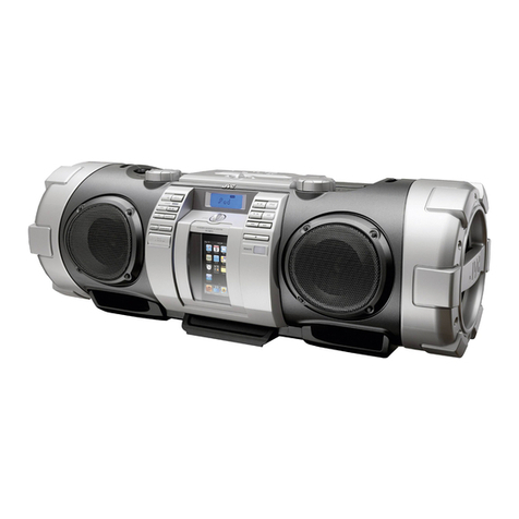
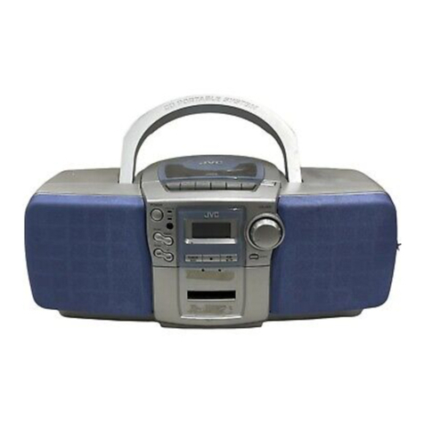
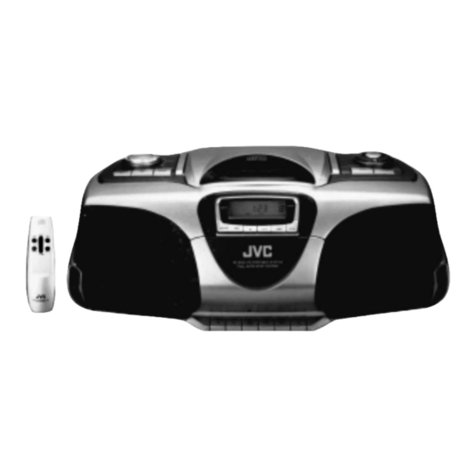
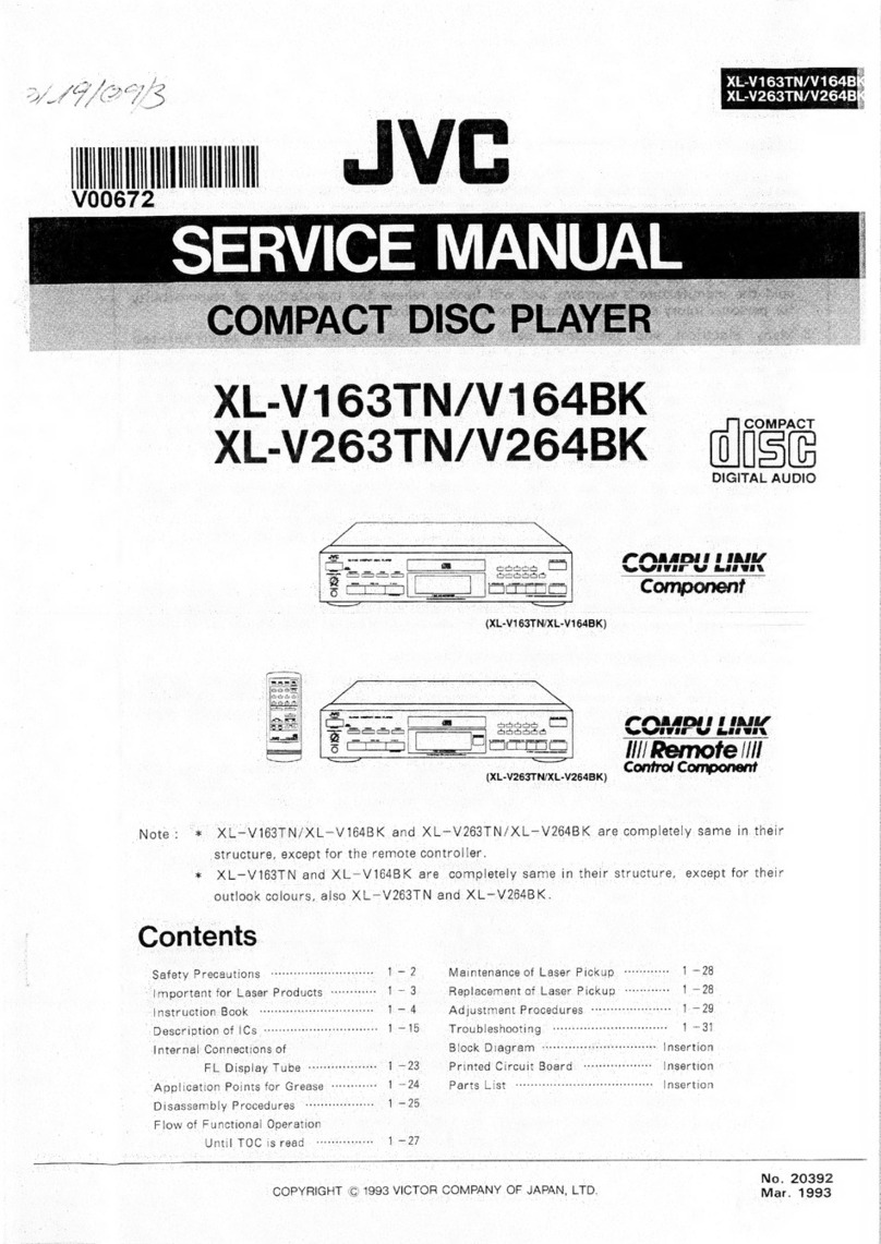
JVC PC-X130 B User manual

PC
—
X130
B/E/G/GI/EN
JVC
SERVICE
MANUAL
COMPACT
DIGITAL
AUDIO
Area
Suffix
Contents
1.
Safety
Precautions-++--+++serssssreerssesseseseneresnens
Page
2
7.
Main
Adjustment
---+++sseceserserreereereeeseteeeeeeneees
+35
2.
Safety
Precaution
about
PC
—
X13
vrrrerrrrrererrerereees
3
B.
Block
Diagram
vocrrseessersrerseesereersnerseersenseteensees
“41
3.
Main
Features
-ssrrccreceessssreeeeeeeeesessrennanensececereereees
5
9.
Wiring
Connections
«--+-+1ssssrseerreerreetseter
etre
tees
-43
A.
Specificationsss:--sereersersseeserseetseeeesseeteeteenneseeeeees
5
40.
Standard
Schematic
Diagram
------+es+eerrrreeee
signe
a8
44
5.
Instructions(Extract)
ssrrrscssseeeeereereseeeeeeeereeseecceerecers
6
11.
Location
of
P.C.
Board
Parts::s-:s:essserrrrer
settee
49
4.
Location
of
Main
Parts----+-+ssssssssesersseeeerssenseeneeenes
24
12.
Electrical
Parts
Lists-:::+ss:sceceeseeeereeeeetseeennermenn
ee
51
5.
Removal
of
Main
Parts
-s::ssscsecsereeseeereceeeeeneeeeeeees
25
13.
Illustration
of
Packing
and
Parts
List
«rst
=
61
6.
Analytic
Drawing
and
Parts
List-:--cscereserseererersereens
28
44.
ACCESSOLICS
orerereseereeeeeeeereeneeeenereeaterees
Bax
cover
a
a
eri
N
Oo.
1892
Juty
1993

PC
—
X130
B/E/G/GI/EN
|
1.
Safety
Precautions
.
The
design
this
product
contains
special
hardware
and
many
circuits
and
components
specially
for
safety
purposes.
For
continued
-
protection,
no
changes
should
be
made
to
the
original
design
unless
authorized
in
writing
by
the
manufacturer.
Replacement
parts
must
be
identical
to
those
used
in
the
original
circuits.
Service
should
be
performed
by
qualified
personnel
only.
.
Alterations
of
the
design
or
circuitry
of
the
product
should
not
be
made.
Any
design
alterations
of
the
product
should
not
be
made.
Any
design
alterations
or
additions
will
void
the
manufacture's
warranty
and
will
further
relieve
the
manufacture
of
responsibility
for
personal
injury
or
property
damage
resulting
therefrom.
.
Many
electrical
and
mechanical
parts
in
the
product
have
special
safety
—
related
characteristics.
These
characteristics
are
often
not
evident
from
visual
inspection
nor
can
the
protection
afforded
by
them
necessarily
be
obtained
by
using
replacement
components
rated
for
higher
voltage,
wattage,
etc.
Replacement
parts
which
have
these
special
safety
characteristics
are
identified
in
the
parts
list
of
service
manual.
Electrical
components
having
such
features
are
identified
by
(
Z\
_
)on
the
schematic
diagram
and
parts
list
in
the
service
manual.
The
use
of
a
substitute
replacement
which
does
not
have
the
same
safety
characteristics
as
the
recommended
replacement
part
shown
in
the
parts
list
of
service
manual
may
create
shock,
fire,
or
other
hazards.
.
The
leads
in
the
products
are
routed
and
dressed
with
ties,
clamps
,
tubings,
barriers
and
the
like
to
be
separated
from
live
parts,
high
temperature
parts,
mpving
parts
and
or
sharp
edges
for
the
prevention
of
electric
shock
and
fire
hazard.
When
service
is
required,
the
original
lead
routing
and
dress
should
be
observed,
and
it
should
be
confirmed
that
they
have been
returned
to
normal,
after
reassembling.
.
Leakage
current
check
(Electrical
shock
hazard
testing)
After
re
—
assembling
the
product,
always
perform
an
isolation
check
on
the
exposed
metal
paris
of
the
product
(antenna
terminals,
knobs,
metal
cabinet,
screw
heads,
headphone
jack,
contro!
shafts,
etc.)
to
be
sure
the
product
is
safe
to
operate
without
danger
of
electrical
shock.
Do
not
use
a
line
isolation
transformer
during
this
check.
+
Plug
the
AC
line
cord
directly
into
the
AC
outlet.
using
a"Leakage
current
tester’,
measure
the
leakage
current
from
each
exposed
metal
part
of
the
cabinet,
particulary
any
exposed
metal
part
having
a
return
path
to
the
chassis,
to
a
known
good
earth
ground.
Any
leakage
current
must
not
exposeed
0.5mA
AC(r.m.s.)
:
AC
VOLTMETER
Alternate
check
method
am
(Having
1000
ohms/volt,
Plug
the
AC
line
cord
directly
into
the
AC
outlet.
Use
an
AC
voltmeter
or
more
sensitivity.)
having
1,000
ohms
per
volt
or
more
sensitivity
in
the
following
1
manner.
Connect
a
1,500
ohms
10W
resistor
paralleled
bya
0.15
2
F
0.15
uF
AC
TYPE
AC
type
capacitor
between
an
exposed
metal
part
and
a
known
good
,
Place
this
probe
earth
ground.
Measure
the
AC
voltage
across
the
resistor
with
the
AC
on
each
exposed
15002
10W
metal
part.
voltmeter.
Move
the
resistor
connection
to
each
exposed
metal
part,
e
particularly
any
exposed
metal
part
having
a
return
path
to
the
Good
earth
ground
chassis,
and
measure
the
AC
voltage
across
the
resistor.
Now,
reverse
the
plug
in
the
AC
outlet
and
repeat
each
measurement.
Any
voltage
measured
must
not
exceed
0.75V
AC(r.m.s.).This
corresponds
to
0.5mA
AC(r.m.s.).
Warning
1.
This
equipment
has
beer
designed
and
manufactured
to
meet
international
safety
standards.
2.
It
is
the
legal
responsibility
of
the
repairer
to
ensure
that
these
safety
standards
are
maintaintaind.
3.
Repairs
must
be
made
in
accordance
with
the
relevant
safety
standards.
4.
It
is
essential
that
safety
critical
components
are
replaced
by
approved
parts.
5.
If
mains
voltage
selector
is
provided,
check
setting
for
local
voltage.
2
(No.
1892)

PC
—
X130
B/E/G/GI/EN
2.
Safety
Precaution
about
PC
—
X130
IMPORTANT
FOR
LASER
PRODUCTS
(PRECAUTION)
PRECAUTIONS
1.
CLASS
1
LASER
PRODUCT
6.
CAUTION:
The
laser
is
able
to
function,
if
safety
swit-
2.
DANGER:
Invisible
laser
radiation
when
open
and
ches
are
out
of
function.
The
laser
light
is
invisible,
avoid
interlock
failed
or
defeated.
Avoid
direct
exposure
{fo
exposure,
do
not
disassemble
the
laser
unit,
but
replace
beam.
the
complete
unit.
3.
CAUTION:
Do
not
open
the
rear
cover.
There
are
no
user
serviceable
parts
inside
the
unit;
leave
all
servicing
to
qualified
service
personnel,
4.
CAUTION:
The
compact
disc
player
uses
Invisible
IDENTIFICATION
LABEL
AND
laser
radiation
and
Is
equipped
with
safety
switches
CERTIFICATION
LABEL
which
prevent
the
emission
of
radiation
when
the
CD
door
Is
open.
It
Is
dangerous
to
defeat
the
safety
switches.
5.
CAUTION:
Use
of
controls
for
adjustments
and
the
performance
of
procedures
other
than
those
specified
herein
may
result
in
exposure
to
hazardous
radiation.
o
|
fl
fol
=
NAME/RATING
PLATE
CLASS
1
LASER
PRODUCT
Obs:
Apparaten
innehdller
laser
Komponent
av
hécer
taserklass
an
klass
1.
ADVARSEL-Der
vil
udstrales
DANGER-invisible
laser
osyniig
laserbestraling
nar
radiation
when
open
and
apparatet
abnes
og
aflas-
interlock
defeated.
ningsmekanismen
frigores.
AVOID
DIRECT
EX-
UNDGA
AT
BLIVE
UDSET
POSURE
TO
BEAM.
FOR
LASERBESTRALING.
IMPORTANT
(In
the
United
Kingdom)
Mains
Supply
(AC
240
V~,
50
Hz
only)
DO
NOT
cut
off
the
mains
plug
from
this
equipment.
If
the
plug
fitted
is
not
sultable
for
the
power
points
in
your
home
or
the
cable
IMPORTANT
is
too
short
to
reach
a
power
point,
then
obtain
an
appropriate
;
.
:
DO
NOT
make
any
connection
to
the
terminal
which
Is
markid
with
safely
approved
extension
lead
or
consult
your
dealer.
the
leiler€
of
by
th
fet
ah
Bal
right
a
e
letter
E
or
@
safely
earth
symbol
or
coloured
gnen
BE
SURE
to
replace
the
fuse
only
with
an
identical
approved
type,
pearandyance:
¥
¥
:
as
originally
fitted,
and
to
replace
tells
covery
The
wires
In
the
mains
lead
on
this
product
are
coloued
in
If
nonetheless
the
mains
plug
Is
cut
off
ensure
to
remove
the
fuse
accordance
with
the
following
code:
and
dispose
of
the
plug
Immediately,
to
avoid
a
possible
shock
hazard
by
Inadvertent
connection
to
the
mains
supply.
Blue
to
N
(Neutral)
orBlack
;
Brown
to
L
(Live)
or
Fed
As
these
colours
may
not
correspond
with
the
coloured
murkimngs
identifying
the
terminals
In
your
plug
proceed
as
follows:
The
wire
which
Is
coloured
blue
must
be
connected
to
the
trminal
which
is
marked
with
the
letter
N
or
coloured
black.
The
wire
which
is
coloured
brown
must
be
connectedto
the
terminal
which
is
marked
with
the
letter
L
or
coloured
red.
IF
IN
DOUBT
-
CONSULT
A
COMPETENT
ELECTRCIAN.
No.
1892)
3

PC
—
X130
B/E/G/GI/EN
|
W@W
Main
P.C.
board
a
=
Ds96~D999
‘A
-
J301
Fuse
:
F997
T999
:
Power
trans
Antenna
wire
Fuse
:
F998
Q921
Must
notprotrude
Q901,1IC101,201
from
soldering
round
Micon
board
Must
be
fixed
wit
Bond
Hi
Inportant
points
for
safety
management
1.
7.
Make
sure
of
the
marking
"VTP57P2
—
12C
(PC
—
X130
B/E/G/GI/EN)”
on
the
power
transformer
as
well
as
of
fixing
screws
got
tightened.
.
Make
sure
of
the
markings
“SE
—
1(PC
—
X130
E/G/GI/EN)
or
SE
—
5
(PC
—
X130
B)"
on
the
attachment
plug
of
the
power
cord,
“SE
—
4
(PC
—
X130
E/G/GI/EN)
or
SE
—
6
(PC
—
X130
B)”
on
its
connector
plug
and
“<q
VDE
>
(PC
—
X130
E/G/GI/EN)
or
BS6500
(PC
—
X130
B)"
mark
on
the
power
cord
itsself
besides
confirmation
of
no
damage
in
any
part
of
the
cord.
.
Make
sure
of
the
marking
“HSC1466
(PC
—
X130
B/E/G/GI/EN)”
on
the
AC
jack
and
of
no
gap
between
the
jack
and
the
board
to
avoid
break
in
the
circuit
pattern.
.
For
securing
creeping
distance
and
space
interval,
make
sure
of
no
excess
soldering
and
no
parts
sticking
out
around
primary
terminals
and
adjacent
secondary
terminals.
.
Make
sure
of
secure
fitting
of
the
fuse
besides
rating,
ampere
—
capacity
and
T
mark
shown
on
its
base.
Especially
check
the
rating
that
is
accordant
with
the
specified
rating
indicated
on
the
board.
F997
:
TSAL250V,
F998
:
TSAL250V
.
Make
sure
that
all
wires
and
the
like
are
securely
clamped
or
fixed
not
to
near
live
parts,
moving
parts,
heat
generation
parts
and
sharp
—
edged
parts.
Make
sure
to
arrange
the
following
parts
not
to
contact
electrolytic
capacitors
and
wires
since
they
are
heat
generation
parts.
For
inflammable
parts,
confirm
that
they
don’
t
topple
down
if
they
are
lifted
up.
(
)must
be
controlled.
1C201,
16101,
Q921,
Q901,
(D996),
(D997), (D998),
(D999),
RMO7.
4
(No.
1892)

Main
Features
Specifications
Compact
disc
player
section
Type
Signal
detection
system
Number
of
channels
Frequency
response
Signal-to-nolse
ratio
Wow
&
flutter
Radio
Section
Frequency
range
Antennas
Tape
deck
Section
Track
system
Motor
Heads
Frequency
response
Wow
&
flutter
Fast
wind
time
General
Power
output
Output
terminals
Compact
disc
player
Non-contact
optical
pickup
(semiconductor
faser)
2
channels
(stereo)
20
Hz
-
20,000
Hz
76
dB
Less
than
measurable
limit
FM
87.5
-
108
MHz
(B/E/G/GI/EN)
MW
522
~
1,629
KHz
(B/E/G/EN)
LW
144
-
288
kHz
(B/E/G/EN)
Telescopic
antenna
for
FM
Ferrite
core
antenna
for
MW
and
LW
:
4-track
2-channel
stereo
Electronic
governor
DC
motor
for
capstan
Deck
A;
Hard
permalloy
head
for
recording/playback,
2
gap
permalloy
head
for
erasure
Deck
8;
Hard
permalioy
head
for
playback
63
-
12,500
Hz
(with
normal
tape/norma!
speed)
0.15%
(WRMS)
Approx.
120
sec.
(C-60
cassette)
Max.
20
W
(10
W
+
10
W)
at
8
Q
PHONES
x1
(Output
level:
0
-
12
MW/32
2,
Matching
impedance:
16
Q-
1k)
|
PC
—
X130
B/E/G/GI/EK
.
Multi-function
CD
player
with
remote
control.
©
CD
player
with
programmed
play
of
up
to
20
tunes/
repeat
play/random
play/intro
play
function.
©
8-cm
(3-3/16")
“CD
singles"
capability.
.
32-key
remote
control
unit
(CD
and
tuner
operations)
®
Remote
control
controls
power
on/off
switching,
volume
control,
SEA
electronic
equalizer
controls,
Active
Hyper-Bass
on/off
switching.
.
Active
Hyper-Bass
circult
for
low-frequency
sound
reproduction.
.
2-Band
digital
synthesizer
tuner with
30-station
(15
FM
and
AM
(MW/LW)
preset
capability
®
Seek/manua!
tuning
®
Auto
preset
tuning
®
Preset
scan
tuning
.
Synchro-record
start
for
CD
recording
convenience.
.
Double-cassette
mechanism
(Deck
A
for
recording
and
playback,
Deck
B
for
playback).
©
Metal
and
CrOz
tapes
can
be
played
back
for
superior
tone
quality.
©
Synchro-start
dubbing
function
(normai/high
speed
dubbing).
@
Relay
playback
(from
Deck
B
to
Deck
A).
.
Timer/Clock
function
@
Timer
on/off
with
preset
volume
function.
©
Wake-up
volume
setting
with
25
different
levels.
®
Sleep
timer
can
be
set
for
up
to
120
minutes.
AC
240
V,
50/60
Hz
(PC-X130B)
AC
230
V,
50/60
Hz
(PC-X130E/G/EN/Gl)
DC
12
V
(“D”
cells
x
8)
Ext.
DC
12
V
(PC
-X130E/EN)
35
W
(with
POWER
SW
ON)
2.6
W
(with
POWER
SW
STANDBY)
700(W)
x
250(H)
x
231(D)
mm
(27-5/8"
x
9-7/8"
x
9-18")
including
knobs
Weight
:
Approx.
8.4
kg
(18.6
Its)
with
batteries
Approx.
7.5
kg
(16.6
Its)
without
batteries
AC
power
cord
Remote
control
unit
(RM-FRX
130)
Battery
“AAA’
x
2
(lorthe
remote
control)
Power
supply
Power
consumption
Dimensions
Accessories
provided
Speaker
Section
(each
unit)
Speakers
:
10
em
(3-15/16°)
x1
Impedance
:
8Q
Dimensions
:
180
(W)
x
237
(H)
201
(D)
mm
(7-1/8"
x
9-3/8"
x
7-11/16")
Weight
:
Approx.
1.6
kg
(3.6
Iks)
Design
and
specifications
are
subject
to
change
wittout
motice.
No-
1892)
5

PC
—
X130
B/E/G/GI/EN
|
Instructions
(
Extract
)
NAMES
OF
PARTS
AND
THEIR
FUNCTIONS
®
Top
panel
e@
Front
panel
@
Disc
hoider
@
Disc
holder
open
button
(4)
©
CD
operation
buttons
@
SEARCH/SKIP
(e-</>1)
buttons
@®
PLAY/PAUSE
(CH)
button
@
STOP/CLEAR
(Q)
button
©
Display
window
(CD
player
section)
@
Function/Track
number
display
®
Playback
time
display
@®
INTRO
scan
Indicator
@
RANDOM
playback
indicator
©
Repeat
playback
indicator
(<=
ALL)
©
Music
calendar
display
@
PRGM
mode
indicator
@®
OVER
indicator
6
(No.
1892)

POWER
ON
STANBY
Still
©
oo
©
=)
ee
ee
|
PC
—
X130
B/E/G/GI/Eh
POWER
button
PRESET
SCAN
button
AUTO
PRESET
button
TUNER
(BAND/FM
MODE)
button
Tuning
(Time
adjustment)
buttons
DOWN
frequency/Hour
or
minute
UP
frequency/Hour
or
minute
VOLUME
buttons
+:
Use
to
increase
the
volume
or
tone
(SEA).
-:
Use
to
decrease
the
volume
or
tone
(SEA).
(The
level
can
be
changed
from
VOL
0
to
VOL
25.)
ACTIVE
HYPER-BASS
button
on:
The
ACTIVE
HYPER-BASS
indicator
will
light.
Set
to
this
position
to
listen
to
the
ACTIVE
HYPER-
BASS
sound
off:
The
ACTIVE
HYPER-BASS
indicator
goes
out.
Set
to
this
position
when
the
ACTIVE
HYPER-
BASS
sound
is
not
required.
ACTIVE
HYPER-BASS
indicator
®
Blinks
when
the
VOLUME
button
is
operated.
Display
window
(Tuner
section)
Band
indicator
(FM/AM)
(MW/LW)
Radio
frequency
display
MONO
indicator
STEREO
indicator
Preset
station
display
(Tape
deck/amplifier
section)
Tape
mode
display
NORMAL
tape
indicator
CrO2/METAL
tape
indicator
NORMAL
speed
indicator
HIGH
speed
indicator
Recording
indicator
(REC)
(Timer/Clock
section)
(See
page
44)
REMOTE
SENSOR
section
SEA
ELECTRONIC
EQ
(FREQUENCY)
button
Used
to
select
the
electronic
equalizer
tequency
band
(100
H2/1
kH2/10
kHz)
to
be
adjusted
wih
the
VOLUME
button.
(The
level
setting
ranges
are
ftom
—5
to
5.)
TAPE
(FOR
PLAYBACK)
switch
Set
this
switch
according
to
the
type
of
fape
to
be
used.
CrOzMETAL:
(playback
only)
Set
to
this
position
to
listen
to
a
metal
(type
IV)
or
chrome
(type
II)
tape.
NORMAL:
Set
to
this
position
to
listen
to
a
normal
(type
|)
tape.
DUBBING
SPEED
switch
HIGH:
Set
to
this
position
when
dubbing
at
hgh-
speed.
NORMAL:
Set
to
this
position
when
dubbing
at
nirm
al-speed.
Cassette
holder
(Deck
A)
Cassette
operation
buttons
(Deck
A)
O
REC:
Press
this
button
with
the
»
PLAY
button
to
start
recording.
>»
PLAY:
Press
to
play
the
tape.
<<
REW:
Press
to
rewind
the
tape
rapidly.
me
FF:
Press
to
wind
the
tape
forward
rapidly.
g/4&
STOP/EJECT:
Press
to
stop
the
tape.
Pressing
this
tutton
when
the
tape
has
stopped
opens
the
cassette
iolcfer.
it
PAUSE:
Press
to
stop
the
tape
momentarily.
Pre
ss
again
to
release
the
pause
mode.
Wo.
1892)
7

PC
—
X130
B/E/G/GI/EN
|
Cassette
holder
(Deck
B)
Cassette
operation
buttons
(Deck
B)
>
PLAY:
Press
to
play
the
tape.
<<
REW:
Press
to
rewind
the
tape
rapidly.
pr
FF:
Press
to
wind
the
tape
forward
rapidly.
w/&
STOP/EJECT:
Press
to
stop
the
tape.
Pressing
this
button
when
the
tape
has
stopped
opens
the
cassette
holder.
86
©
Rear
panel
S
SPEAKER
terminals
Connect
the
provided
speakers
to
these
terminals.
Battery
compartment
cover
Headphones
jack
(PHONES)
(3.5
mm
dia.
stereo
mini)
Connect
headphones
(impedance
16
Q
-
1
kQ)
to
this
jack.
The
speakers
are
automatically
switched
off
when
the
headphones
are
connected.
AC
IN
(AC
Input)
Jack
Telescopic
antenna
ee
ee
DC
IN
12V
(PC-X130E/EN)
8
(No.
1892)

|
PC
—
X130
B/E/G/GI/Et
(_
REMOTE
CONTROL
UNIT
The
following
operations
can
be
performed
using
the
remote
contro!
unit.
@
Check
the
functions
of
the
operation
buttons
carefully
and
operate
them
correctly.
@
wCLEAR:
Stop/clear
button
@
CD
p/u:
CD
mode/play/pause
button
©
CD
search/DOWN
and
UP
buttons
(4,
bP)
@
in
the
CD
mode,
to
scan
to
the
beginning
of
a
tune
and
to
start
forward
or
reverse
search.
®
inthe
tuner
mode,
to
tune
to
broadcasts.
(Also
used
to
set
the
time
and
timer.)
INTRO
button
MEMORY/CALL
button
Track
(tune)
number
buttons
(No.
1
—
No.
10,
+10)
Preset
station
buttons
(No.
1
—
No.
10,
+10)
CLOCK
button
CLOCK
SET
button
ACTIVE
HYPER-BASS
button
SLEEP
button
POWER
(AC)
button
@
When
power
is
supplied
from
the
batteries,
even
when
the
button
is
pressed,
the
PC-X130
will
not
be
switched
on.
TUNER/BAND
button
FM
MODE
button
PRESET
SCAN
button
AUTO
PRESET
button
RANDOM
button
REPEAT
button
ENTER
button
TIMER
ON/OFF
button
TIMER
SET
button
VOLUME
buttons
+:
Use
to
increase
the
volume
or
tone
(SEA).
-:
Use
to
decrease
the
volume
or
tone
(SEA).
FREQUENCY
(ELECTRONIC
EQUALIZER)
button
6009
908
Geeceo0e
8
8
cS)
ATTACHING/DETACHING
THE
SPEAKERS
When
using
the
speakers
attached
to
the
main
unit
Hold
with
the
bottom
of
the
speaker
against
the
top
of
the
main
unit
and
press
down
on
the
speaker
to
attach
it.
k
x
Speakel
act
*
Press
the
speaker
down
with
the
speaker
and
main
unit
aligned.
Main
unit
(o-
1892)
9

PC
—
X130
B/E/G/GI/EN
|
When
using
the
speakers
detached
from
the
main
unlt
Lift
the
speaker
up
to
detach
from
the
main
unit
by
pressing
the
lock
lever
at
the
rear
bottom
of
speaker
in
the
direction
of
the
arrow.
Lock
lever
Note:
Since
the
speakers
sound
differently
according
to
where
they
are
placed,
carefully
place
them
for
optimal
effect
within
the
length
of
the
provided
speaker
cords.
It
Is
recommended
that
the
left
and
right
speakers
be
placed
symmetrically
in
relation
to
the
main
unit.
(
CONNECTIONS
®
Do
not
switch
the
power
on
until
all
the
connections
are
completed.
*
After
connecting
the
speaker
cords,
‘
bundle
any
sien
into
itis
space
for
*
When
connecting
the
speaker
cords,
*
the
speaker
cords
in
the
rear
panel
connect
the
one
marked
with
a
line
to
the
“~
P
p
.
terminal
first.
*
Space
for
speaker
cords
©
Marked
with
line
10
(No.
1892)

|
PC
—
X130
B/E/G/GI/E:
PLAYING
COMPACT
DISCS
ZX
Playing
an
entire
disc
...
The
following
example
assumes
a
compact
disc
with
12
tunes
and
a
total
playing
time
of
48
minutes
57
seconds.
Operate
in
the
order
shown
[A
@
Set
the
POWER
button
to
on.
@
Press
to
open
the
Disc
holder.
©
Load
a
disc
with
the
label
side
facing
up
and
close
the
Disc
holder.
@
Set
to
the
CD
mode.
@
{Ifthe
PLAY
button
of
deck
A
or
B
is
pressed,
press
the
STOP/EJECT
(m/4)
button
to
set
to
the
stop
mode.
®
When
aCDis
first
loaded,
the
total
number
of
tracks
(tunes)
and
total
playing
time
are
displayed.
@
Press
to
start
play.
©
As
tunes
are
played,
their
track
numbers
go
out
one
by
one.
®
8-cm
(3-3/16")
compact
discs
can
be
used
in
this
unit
without
an
adapter.
To
adjust
the
SEA
(FREQUENCY)
electronic
equalizer
equalizer
frequency
band
(100
Hz/1
kHz/10
kHz)
to
be
adjusted.
Within
about
5
seconds,
press
the
VOLUME
button
(+/-)
to
adjust
the
level
within
a
range
of
-5
to
5.
{Level
should
be
adjusted
in
each
frequency
band.)
Press
the
SEA
(FREQUENCY)
button
to
select
the
sie
bs
To
stop
play
¢
To
stop
in
the
middle
of
a
disc
During
playback,
press
the
STOP/CLEAR
(0)
button
to
stop
play.
No.
1892)
11

PC
—
X130
B/E/G/GI/EN
|
¢
To
stop
a
disc
temporaril
Press
the
PLAY/PAUSE
tw)
button
to
stop
play
temporarily.
When
pressed
a
play
resumes
from
the
point
where
it
was
paused.
Caution:
®
To
change
discs,
press
the
STOP/CLEAR
(Q)
button;
check
that
the
disc
has
stopped
rotating
completely
before
unloading
it.
Notes:
®
The
following
indication
may
be
shown
when
a
disc
is
aly
or
scratched,
or
when
the
disc
is
loaded
upside
lown.
In
such
a
case,
check
the
dise
and
insert
again
after
cleaning
the
disc
or
turning
it
over.
Keep
pressing
for
fast-reverse
search
Direct
access
playback
(using
the
remote
control)
@
Pressing
any
of
the
track
number
buttons
will
start
playing
from
the
beginning
of
the
designated
tune,
without
your
having
to
press
the
CD
m/it
button.
(This
function
cannot
be
used
during
programmed
play.)
w/CLEAR
12
(No.
1892}
®
Do
not
use
the
unit
at
excessive
high
or
cold
temperatures.
The
recommended
temperature
range
is
from
5°C
(41°F)
to
35°C
(95°F).
e
After
playback,
unload
the
disc
and
close
the
Disc
holder.
®
If
mistracking
occurs
during
play,
lower
the
volume.
@
Mistracking
may
occur
if
a
strong
shock
is
applied
to
the
unit
or
if
itis
used
in
a
place
subject
to
vibrations
(i.e.
in
a
car
travelling
on
a
rough
road).
Skip
playback
@
During
playback,
it
is
possible
to
skip
forward
to
the
beginning
of
the
next
tune
or
back
to
the
beginning
of
the
tune
being
played
or
the
previous
tune;
when
the
beginning
of
the
required
tune
has
been
located,
play
starts
automatically.
To
listen
to
the
next
tune
...
Press
the
m1
button
once
to
skip
to
the
beginning
of
the
next
tune.
To
listen
to
the
previous
tune
...
Press
the
<4
button
to
skip
to
the
beginning
of
the
tune
being
played
back
and
press
again
to
skip
to
the
beginning
of
the
previous
tune.
Search
playback
(to
locate
the
required
position
on
the
disc)
©
The
required
position
can
be
located
using
fast-forward
or
reverse
search
while
playing
a
disc.
Ke
SEARCH
DPI
1
SKIP
Keep
pressing
for
fast-forward
search
@
Hold
down
the
button;
search
play
starts
slowly
and
then
gradually
increases.
in
speed.
©
Since
low-volume
sound
(at
about
one
quarter
of
the
normal
level)
can
be
heard
in
the
search
mode,
monitor
the
sound
and
release
the
button
when
the
required
position
is
located.
@
Press
the
w/CLEAR
buiton
to
set
to
the
CD
mode.
@
if
the
PLAY
button
of
the
deck
A
or
B
is
pressed,
press
the
STOP/EJECT
(m/4)
button
to
set
to
the
stop
mode.
@
Designate
the
required
tune
using
the
track
number
buttons.
@
To
designate
tune
numbers
1
to
10,
press
the
track
number
button
corresponding
to
the
tune
(track)
number.
©
To
designate
tune
number
11
or
higher,
press
the
+10
button
the
required
number
of
times,
then
the
track
number
button.
(Example:
To
designate
the
25th
tune,
press
the
+10
button
twice,
then
press
track
number
button
5.)
*
+10
button:
Each
time
this
button
is
pressed,
the
number
increases
by
10.
First
press
this
button
to
set
the
10’s
digit,
then
press
the
track
number
button
to
set
the
1's
digit.
®
To
skip
to
another
tune
during
play
When
the
required
track
number
button
is
pressed,
the
display
shows
the
designated
track
number
and
play
starts
from
the
beginning
of
the
designated
tune.

|
PC
—
X130
B/E/G/GI/EI
Programmed
play
(using
the
remote
control)
©
Upto
20
tunes
can
be
programmed
to
be
played
in
any
Press
the
m/CLEAR
button.
@
required
order.
@®
Press
the
MEMORY
button
to
set
to
the
programming
The
total
playing
time
of
programmed
tunes
is
displayed
mode.
(up
to
99
minutes,
59
seconds).
@
Press
to
designate
the
required
track
number.
(Example:
When
programming
the
2nd
tune
to
be
@
Designate
the
remaining
tunes
by
pressing
the
track
®
played
first,
the
6th
tune
next,
and
then
the
12th
tuna,
number
buttons.
etc.)
Press
the
»/t
button
when
programming
ts
completed.
Programmed
playback
starts.
To
clear
the
programmed
tunes
...
Press
the
m/CLEAR
button
before
playing
a
disc.
During
programmed
playback,
press
this
button
twice.
When
the
Dise
holder
is
opened,
programmed
tunes
are
cleared
automatically.
.
oH
To
designate
the
2nd
tune.
@
To
designate
the
12th
tune.
+10
The
total
playback
time
of
programmed
tunes
Is
displayed.
OR
OX
The
12th
tune
QO
om
To
confirm
the
detalis
of
a
program
...
Press
the
MEMORY/CALL
button;
the
tunes
making
up
the
program
will
be
displayed
in
programmed
order.
MEMORYICALL
Notes:
1.
If
the
total
playing
time
of
the
programned
tunes
exceeds
99
minutes
59
seconds,
the
total
phying
time
indication
will
go
out.
It
is
not
possible
to
program
more
than
20
tirses.
.
When
a
dise
with
16
or
more
tunes
is
Icaced,
the
“OVER™
indicator
will
appear.
4.
When
performing
timer
playback
in
the
order
of
“Programmed
play”,
step
6
above
is
not
reysired.
Tune
number
Program
order
number
en
(Np.
1892)
13

2C
—.X130
B/E/G/GI/EN
|
Repeat
play
(using
the
remote
control)
Press
the
REPEAT
button
before
or
during
play.
A
single
tune
or
all
the
tunes
can
be
repeated.
Whether
a
single
tune
or
all
tunes
are
to
be
repeated
can
be
specitied.
Each
time
the
REPEAT
button
is
pressed,
the
mode
will
change
from
a
single
tune
(
c
),
to
all
the
tunes
(=
ALL),
to
the
clear
mode,
In
this
order.
REPEAT
LY
>
=
Y
All
tunes
©
Repeat
playback
of
a
single
tune
(c=)
The
tune
being
played
back
will
be
heard
repeatedly.
®
Repeat
playback
of
all
tunes
(<>
ALL)
When
playing
back
an
entire
disc
or
programmed
tunes,
all
tunes
or
the
programmed
tunes
will
be
heard
repeatedly.
Random
playback
(using
the
remote
control)
Press
the
RANDOM
button,
all
tunes
on
a
disc
are
played
once,
in
random
order.
INTRO
scan
operation
(using
the
remote
control)
©
Simply
press
the
INTRO
scan
button
to
play
the
first
15
seconds
of
each
tune.
The
operation
Is
released
after
playing
the
introductions
of
all
tunes
or
all
programmed
tunes.
®
Ifthe
INTRO
scan
button
Is
pressed
in
the
middle
of
a
tune,
the
intro
scan
operation
will
start
from
the
next
tune.
®
Torelease
the
intro
scan
mode,
press
the
INTRO
scan
button
again
and
norma!
playback
(or
programmed
playback)
will
resume.
|
uaa
INTRO
fioed
|
14
(No.
1892)
(
CASSETTE
PLAYBACK
(SSR)
(The
example
shows
Deck
A)
Operate
in
the
order
shown
Set
the
POWER
button
to
on.
Load
a
cassette.
Set
the
TAPE
switch
as
required.
Press
to
start
playback.
Adjust.
OOOO
Playback
in
Deck
B
The
previous
procedures
@
through
@
also
apply
to
Deck
B
when
a
cassette
is
loaded
in
Deck
B.
When
Decks
AandB
are
simultaneously
set
to
the
play
mode,
only
the
playback
sound
of
Deck
B
is
heard.
Notes:
1.
When
the
power
is
turned
off
while
the
tape
is
still
running,
cassette
operation
buttons
which
are
depressed
do
not
return
to
the
original
positions.
Press
the
STOP/EJECT
(m/4)
button
to
stop
the
tape
tunning
before
turning
off
the
power.
2.
Avoid
operating
the
FF
or
REW
button
on
the
deck
during
playback
of
the
other deck.
@&®
ALL
o>
Goes
off
Repeat
playback
Is
released.

|
PC
—
X130
B/E/G/GI/E!
RELAY
PLAYBACK
[ToAOT]
am
[L282]
(From
Deck
B
to
Deck
A)
Operate
in
the
order
shown
Set
the
POWER
button
to
on.
Load
a
cassette.
Load
a
cassette.
Set
the
TAPE
switch
as
required.
Press
the
»
PLAY
button
on
Deck
B.
Set
Deck
A
to
the
play-pause
mode.
QOO006
When
Deck
8
stops,
Deck
A's
pause
mode
will
be
released
and
it
will
start
playback.
When
Deck
A
stops
automatically,
relay
playback
will
be
released.
Note:
Use
the
same
type
of
tape
in
Decks
A
and
B
during
this
mode.
(
RADIO
RECEPTION
>
:
Operate
in
the
order
shown
FM
MODE
button
Auto
mode:
Set
to
this
position
when
listening
to
or
recording
an
FM
stereo
broadcast.
The
STEREO
indicator
lights
when
a
FM
stereo
broadcast
is
received.
MONO:
Set
to
this
position
when
FM
Stereo
reception
is
noisy.
When
another
station
is
tuned
to
in
the
MONO
mode
using
the
TUNING
UP/DOWN
or
PRESET
SCAN/ALTO
PRESET
button,
the
unit
automatically
enters
Auto
made.
®
Seek
tuning
Press
the
UP
or
DOWN
button
for
one
sesortd
or
more;
the
unit
enters
the
seek
tuning
mode
and
tunes
to
higher
or
lower
frequencies,
and
when
th»
broadcast
is
received,
itstops
tuning
automatically
ancihe
broadcast
can
be
heard.
@
Set
the
POWER
button
to
on.
@
Press
the
TUNER/BAND
button;
a
band
and
radio
frequency
will
be
shown
in
the
display.
©
Ifthe
PLAY
button
of
the
deck
is
pressed,
press
the
STOP/EJECT
(m/4)
to
set
to
the
stop
mode.
@
Select
the
band/FM
mode
(FM
auto,
FM
MONO
or
AM)
(MW/LW).
@
Tune
to
the
required
station.
(fo.
1892)
15

PC
X130
BIE/G/GIEN
|
Manual
tuning
Each
time
the
UP
or
DOWN
button
is
pressed,
the
unit
steps
through
the
current
frequency
band.
Tuning
is
in
steps
of
100
kHz
for
FM
and
10
kHz
for
AM
(MW/LW).
Press
to
move
to
higher
frequency
Notes:
.When
seek
tuning
to
the
required
station
is
not
possible
because
itis
broadcasting
too
weak
a
signal,
press
the
UP
or
DOWN
button
momentarily
to
perform
manual
tuning.
When
the
power
is
set
to
STANDBY,
or
another
mode
(TAPE
or
CD)
is
selected,
the
last
tuned
frequency
Is
stored
inmemory.
When
the
power
is
switched
on
again
and
TUNER/BAND
button
Is
pressed,
the
same
station
a
Cvsee
|
83
WA
TUNING
Auto
preset
tuning
Press
to
move
to
lower
frequencies
This
function
scans
the
current
band
(FM-or
AM
(MW/
LW),
detecting
frequencies
used
to
broadcast
signals,
and
stores
the
first
15
frequencies
in
mamory
automaticlaly.
@
Press
the
AUTO
PRESET
button
for
more
than
2
seconds.
The
frequencies
of
stations
broadcasting
signals
can
be
preset
automatically
in
the
order
of
increasing
frequency.
(15
stations
in
each
band
(FM
will
be
heard.
a
stations
(using
the
remote
control
un
15
stations
in
each
band
(FM
and
AM
(MW/LW))
can
be
preset
as
follows:
»
Example
(when
presetting
an
FM
station
broadcasting
at
103.5
MHz
to
preset
button
“15")
and
AM
(MW/LW).
Press
the
TUNER/BAND
button.
‘Select
the
FM
band
using
the
TUNER/BAND
button.
Tune
to
the
required
station.
Press
preset
button
*+10",
then
“5” for
more
than
2
sec.
(When
“15”
blinks
In
the
preset
station
display,
the
Station
has
been
preset.)
Repeat
the
above
procedure
for
each
of
the
other
stations,
using
a
different
preset
button
each
time.
Repeat
the
avove
procedure
for
the
AM
(MW/LW)
band.
®
To
change
preset
stations
Perform
step
@
above
after
tuning
to
the
required
station.
O80
16
(No.
1892)
Not
e
es:
The
previous
preset
station
is
erased
when
a
new
station
Is
set
as
the
new
station's
frequency
replaces
the
previous
frequency
in
memory.
When
listening
to
an
AM
broadcast,
noise
may
be
heard
if
the
remote
control
is
used.

|
PC
—
X130
B/E/G/GI/E
Preset
tuning
(using
the
remote
control
unit)
®
The
stations
must
be
preset
before
this
operation
can
be
performed.
@
Press
the
TUNER/BAND
button.
@®
Select
the
band
(FM
or
AM
(MW/LW))
using
the
TUNER/BAND
button.
@®
Press
the
required
preset
station
buttons
(No.
1
—
No.
10,
+10).
The
preset
station
number
and
frequency
corresponding
to
the
button
pressed
are
shown.
Preset
scan
button
tuning
0)
Ogee
©
This
makes
it
possible
to
automatically
scan
preset
FM
i
oo
bh
Nain
—O0}G}G+GEEI-E)
Preset
stations
@
Press
the
PRESET
SCAN
button.
@
Scanning
is
performed
in
the
order
of
preset
station
@
eee
in
each
frequency
band
(FM
and
AM
(MW/LW)).
Each
preset
station
is
heard
for
approx.
5
seconds.
@
When
the
required
station
is
heard
and
its
frequency
is
blinking,
press
the
PRESET
SCAN
button
again.
Note:
Up
to
15
broadcast
stations
in
each band
can
be
preset
on
the
PC-X130.
!f
the
preset
scan
operation
Is
performed
without
all
15
stations
having
been
preset,
noise
may
be
heard
under
certain
conditions
when
non-preset
stations
are
scanned.
Using
the
antennas
RECORDING
FM
@
jn
recording,
the
ALC
circuit
automatically
optimizes
the
recording
level;
adjustment
of
the
recording
level
is
unnecessary.
@
Check
that
the
safety
tab
on the
cassette
tipe
Is
not
broken
off.
MW
or
LW
Notes:
1.
The
recording
characteristics
of
this
unit
ar:
those
of
normal
tape.
Normal
tape
has
different
chancteristics
from
CrO,
and
metal
tapes.
2.
Do
not
operate
any
button
on
deck
B
during
ecording.
It
should
be
noted
that
it
may
be
unlawful
to
n-re-
cord
pre-recorded
tapes,
records,
or
discs
without
thecorssent
of
the
owner
of
copyrightin
the
sound
or
video
recoreding,
Note:
broadcast
or
cable
programme
and
in
anylite
sary,
The
built-in
ferrite
core
antenna
can
pick
up
Interference
dramatic,
musical,
or
artistic
work
embodied
herein.
from
television
receivers
in
the
neighborhood
and
thereby
disturb
AM
(MW/LW)
reception.
No.
1892)
17

PC
—
X130
B/E/G/GI/EN
|
Synchronized
recording
with
the
CD
player
®
In
this
system,
the
CD
player
starts
playback
when
Deck
A
enters
the
recording
mode.
Operate
In
the
order
shown
@
Load
a
cassette
tape
in
deck
A
@
Load
a
disc
and
close
the
Disc
holder.
©
Set
the
CD
mode.
@
When
the
»
PLAY
button
of
deck
is
pressed,
press
A
———
TE
f
|
I
ee
Re
WC,
the
STOP/EJECT
(m/4)
button
to
set
to
the
stop
mode
and
perform
this
operation.
@
When
programmed
playback
is
required,
program
the
required
tunes
using
the
remote
control.
(See
page
27.)
®
Select
tunes
with
a
total
playing
time
which
does
not
exceed
the
tape
length.
@
Press
the
O
REC
button
with
the
»
PLAY
button;
synchronized
recording
will
start.
®
Non-recorded
sections
of
approx.
4
seconds
are
automatically
left
between
tunes.
@
When
the
tape
reaches
the
end
first,
the
CD
player
stops
automatically;
when
the
CD
player
stops
first,
the
tape
continues
running.
In
this
case,
press
the
m/Aa
STOP/EJECT
button
to
stop
the
tape.
@
When
automatic
spacing
between
tunes
Is
not
required
...
Perform
the
following
after
finishing
the
previous
operation
(@
to
@).
@
Press
the
>t!
PLAY/PAUSE
button
of
the
CD
player
twice.
The
CD
player
enters
the
pause
mode.
@®
Press
the
O
REC
and»
PLAY
buttons
simultaneously.
Now,
the
CD
player
starts
playback
simultaneously.
18
(No.
1892)

PC
—
X130
B/E/G/GI/El
DUBBING
(SYNCHRO
START
DUBBING)
Pees.
Normal
and
high-speed
dubbing
can
be
done
from
Deck
B
to
Deck
A.
Operate
in
the
order
shown
Load
a
cassette
tape
in
deck
A.
(Refer
to
the
note
¢
page
38.)
Load
a
pre-recorded
cassette
tape
in
deck
B.
®
Slightly
press
the
»
PLAY
button
to
set
to
TAF
mode.
(The
button
should
not
be
flocked.)
Set
to
NORMAL
SPEED
or
HIGH
SPEED.
Set
to
correspond
to
the
type
of
tape
in
Deck
B.
Press
the
#
PAUSE
button.
Press
the
©
REC
button
with
the
»
PLAY
butto
(Record-pause
mode.)
Press
the
»
PLAY
button.
(Synchronized
dubbing
w
start.)
®
©
©
8680
Notes:
1.
Television
receivers
placed
close
tothis
unit
may
cat
interference
on
the
recorded
signal
when
this
unii
used
in
the
high-speed
dubbing
mode.
If
this
happe:
either
turn
off
the
television
receiver
or
use
the
norm
‘speed
dubbing
mode.
2.
With
Deck
A
in
the
record-pause
mode,
the
#1
PAU.
button
Is
released
when
Deck
B
enters
the
stop
mor
Recording
from
the
radio
Operate
In
the
order
shown
Erasin
asing
@
Load
a
cassette.
(Deck
A)
When
recording
on
a
pre-recorded
tape,
the
previous
4
ae
the
TUNER/BAND
button.
recording
is
automatically
erased
and
only
the
new
material
une
to
the
required
station.
canbe
heard
when
the
tape
is
played.
©
Press
the
O
REC
button
with
the
»
PLAXY
button.
To
erase
a
tape
without
making
a
new
recording
...
.
:
Slightly
press
the
»
PLAY
button
of
the
deck
to
set
to
the
©
To
stop
recording
temporarily,
press
the
Wl
PAUS!
TAPE
mode
and
press
the
O
REC
and
»
PLAY
buttons
aN
ge
recording,
pres;
tne
tl
PAUSI
together
after
pressing
the
stop
button.
(lo.
1892)
19

PC
—
X130
B/E/G/GI/EN
|
(
CLOCK
ADJUSTMENT
(Using
the
remote
control)
Names
of
parts
in
the
clock/time
section,
and
their
functions:
Timer
mode
indicator
SLEEP
indicator
Timer
indicator
(ON/OFF)
Time
display
DOWN/UP
button
(Used
to
set
the
time
and
timer)
CLOCK
button
CLOCK
SET
button
SLEEP
button
ENTER
button
TIMER
ON/OFF
button
TIMER
SET
button
B6OG9O
GO800
Setting
the
current
time
(when
the
PC-X130
Is
used
first
time)
(Example:
to
set
the
clock
to
PM
1:15)
7
\
i
Bo
oe
re
er
P
a
t
1
Bat
er"
me
toe
yon
©
ENTER
\
i
SB
ay
ae
i
3
Lf
Li
=
7
|
\
©
ENTER
J
Mekoy
Ly
nN
|
I
Nee
7
uy
us
VaaIN
20
(No.
1892)
®@
DOWN
bed
UP
Bot
@
Connect
the
AC
power
cord;
“AM
12:00”
will
blink
in
the
display.
®
Set
the
POWER
button
to
on.
@®
Press
the
CLOCK
SET
button;
the
hour's
digits
will
blink.
Set
to
PM
1:00
by
pressing
the
UP/DOWN
buttons.
Press
the
ENTER
button;
the
minute's
digits
will
blink.
Set
to
PM
1:15
by
pressing
the
UP/DOWN
buttons.
Press
the
ENTER
button;
the
time
will
light
in
the
display.
©8e00
Each
time
the
hour's
digits
change
from
11
to
12,
the
display
alternates
between
AM
and
PM.
(12
midnightis
indicted
as
“AM
12:00”
and
12
noonis
indicated
as
“PM
12:00")
®
To
set
to
the
nearest
second
...
Press
the
ENTER
button
when
you
hear
the
time
signal
trom
a
TV
or
radio.
Notes:
®
Before
performing
timer
recording
or
playback,
it
is
necessary
to
set
the
current
time.
©.
Press
the
CLOCK
button
to
display
the
current
time
during
CD
play,
tape
play
or
radio
reception.
The
current
time
will
be
displayed
for
10
seconds
after
which
the
display
returns
to
the
previous
mode.
This manual suits for next models
4
Table of contents
Other JVC CD Player manuals

JVC
JVC LVT1977-002B User manual

JVC
JVC RC-EZ38S User manual

JVC
JVC XL-PG31 User manual

JVC
JVC CHX1500 - CD Changer Administrator Guide

JVC
JVC XL-PM5 - CD / MP3 Player User manual
JVC
JVC XL-MC222BK User manual

JVC
JVC 0404SKMCREORI User manual

JVC
JVC RC-ST1SL User manual

JVC
JVC CH-X1200J User manual

JVC
JVC RC-EZ34S User manual