APOGEE ELECTRONICS
iii
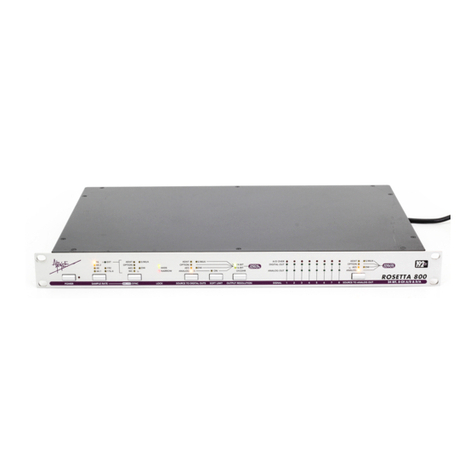
ROSETTA 800 – User’s Guide
Registration and Warranty Information
Be sure to register your Rosetta 800, either by filling in the enclosed Registration Card or by
completing the on-line registration form at our Web site: http://www.apogeedigital.com/support/. If
you do so, Apogee can contact you with any update information. As enhancements and upgrades are
developed, you will be contacted at the registration address. Firmware updates are free for the first
year of ownership unless otherwise stated. Please address any inquiries to your dealer or directly to
Apogee at:
APOGEE ELECTRONICS CORPORATION,
3145 Donald Douglas Loop South, Santa Monica, CA 90405, USA.
TEL: (310) 915-1000, FAX: (310) 391-6262
APOGEE ELECTRONICS CORPORATION warrants this product to be free of defects in material and
manufacture under normal use for a period of 12 months. The term of this warranty begins on the
date of sale to the purchaser. Units returned for warranty repair to Apogee or an authorized Apogee
warranty repair facility will be repaired or replaced at the manufacturer’s option, free of charge.
ALL UNITS RETURNED TO APOGEE OR AN AUTHORIZED APOGEE REPAIR FACILITY MUST
BE PREPAID, INSURED AND PROPERLY PACKAGED, PREFERABLY IN THEIR ORIGINAL BOX.
Apogee reserves the right to change or improve design at any time without prior notification. Design
changes are not implemented retroactively, and the incorporation of design changes into future units
does not imply the availability of an upgrade to existing units.
This warranty is void if Apogee determines, in its sole business judgment, the defect to be the result
of abuse, neglect, alteration or attempted repair by unauthorized personnel.
The warranties set forth above are in lieu of all other warranties, expressed or implied, and Apogee
specifically disclaims any and all implied warranty of merchantability or of fitness for a particular
purpose. The buyer acknowledges and agrees that in no event shall the company be held liable for
any special, indirect, incidental or consequential damages, or for injury, loss or damage sustained by
any person or property, that may result from this product failing to operate correctly at any time.
USA: Some states do not allow for the exclusion or limitation of implied warranties or liability for
incidental or consequential damage, so the above exclusion may not apply to you. This warranty
gives you specific legal rights, and you may have other rights which vary from state to state.
Service Information
The Rosetta 800 contains no user-serviceable components: refer to qualified service personnel for
repair or upgrade. Your warranty will be voided if you tamper with the internal components. If you
have any questions with regard to the above, please contact Apogee.
In the event your Rosetta 800 needs to be upgraded or repaired, it is necessary to contact Apogee
prior to shipping, and a Return Materials Authorization (RMA) number will be assigned. This number
will serve as a reference for you and helps facilitate and expedite the return process. Apogee requires
that shipments be pre-paid and insured — unless otherwise authorized in advance.
IMPORTANT: ANY SHIPMENT THAT IS NOT PRE-PAID OR IS SENT WITHOUT AN RMA
NUMBER WILL NOT BE ACCEPTED.

