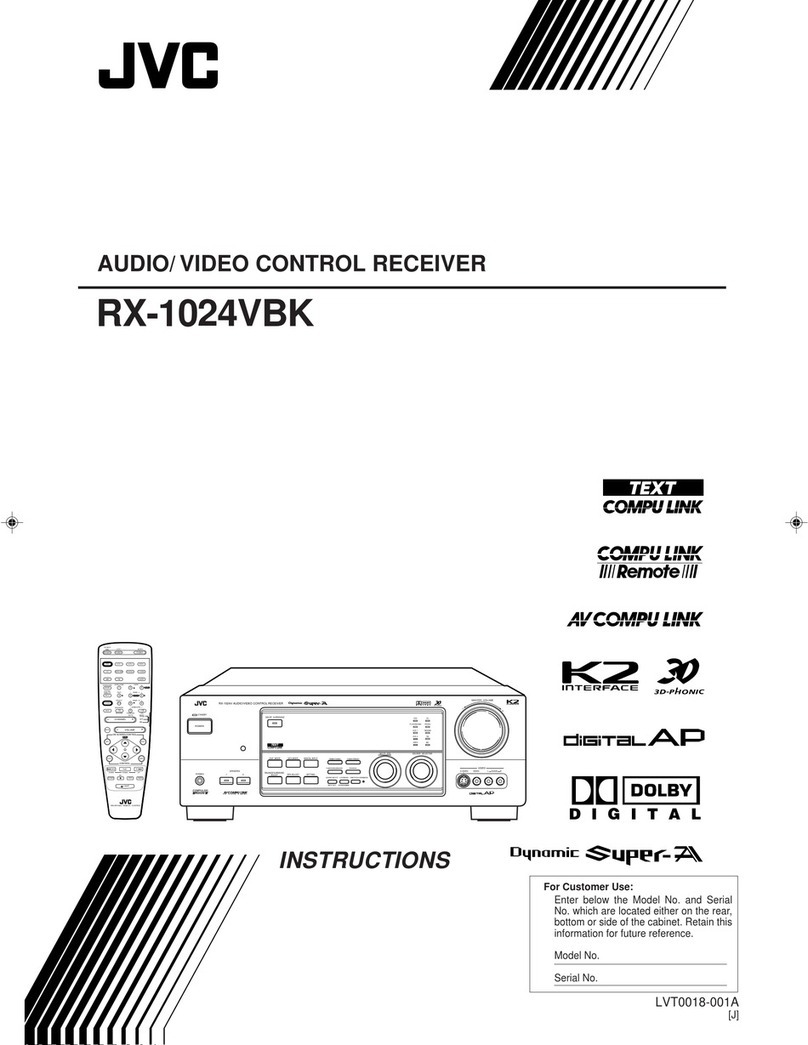
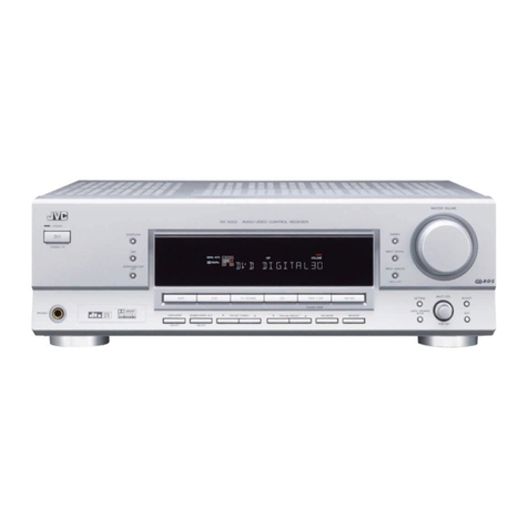
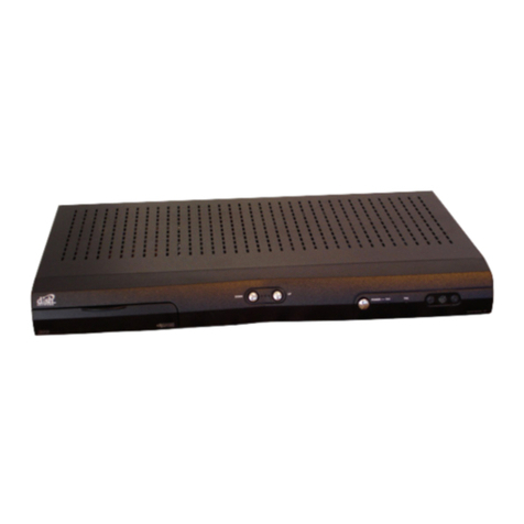
JVC RX-509VTN User manual

INSuisiereure)\
=
RX-509VTN/RX-508VBK
DIGITAL
SURROUND
SYSTEM
RECEIVER
PPP
AsBil
§
ally
WoWITET
W
Soll
U8\
lili
Remote
/I!|
Control
Component
E30580-8
926A
IC,
U,
G,
BS,
A,
EF]

IMPORTANT
for
the
U.K.
DO
NOT
cut
off
the
mains
plug
from
this
equipment.
If
the
plug
fitted
is
not
suitable
for
the
power
points
in
your
home
or
the
cable
is
too
short
to
reach
a
power
point,
then
obtain
an
appropriate
safety
approved
extension
lead
or
consult
your
dealer.
BE
SURE
to
replace
the
fuse
only
with
an
identical
approved
type,
as
originally
fitted.
If
nontheless
the
mains
plug
is
cut
off
ensure
to
remove
the
fuse
and
dispose
of
the
plug
immediately,
to
avoid
a
possible
shock
hazard
by
inadvertent
connection
to
the
mains
supply.
If
this
product
is
not
supplied
fitted
with
a
mains
plug
then
follow
the
instructions
given
below:
IMPORTANT.
DO
NOT
make
any
connection
to
the
terminal
which
is
marked
with
the
letter
E
or
by
the
safety
earth
symbol
or
coloured
green
or
green-and-yellow.
|
The
wires
in
the
mains
lead
on
this
product
are
coloured
in
accordance
with
the
following
code:
Blue
:
Neutral
Brown:
Live
As
these
colours
may
not
correspond
with
the
coloured
markings
identifying
the
terminals
in
your
plug
proceed
as
follows:
The
wire
which
is
coloured
blue
must
be
connected
to
the
terminal
which
is
marked
with
the
letter
N
or
coloured
black.
The
wire
which
is
coloured
brown
must
be
connected
to
the
terminal
which
is
marked
with
the
letter
L
or
coloured
red.
IF
INDOUBT
-
CONSULT
A
COMPETENT
ELECTRICIAN.
THIS UNIT
IS
PRODUCED
TO
COMPLY
WITH
DIRECTIVE
76/889
EEC.
DIESES
GERAT
ENTSPRICHT
EG-RICHTLINIE
87/308
EWG.
CET
APPAREIL
A
ETE
FABRIQUE
POUR
ETRE
CONFORME
A
LA
DIRECTIVE
CEE
NUMERO
87/308/CEE.
DIT
APPARAAT
VOLDOET
AAN
DE
EISEN
GESTELD
IN
DE
CEE
BEPALING
87/308.
ESTA
UNIDAD
SE
PRODUCE
PARA
CUMPLIR
CON
LA
DIRECTIVA
87/308/CEE.
CONFORME
AL
D.M.
13
APRILE
1989
DIRETTIVA
CEE/87/308.
IMPORTANT
(CANADA
ONLY/CANADA
SEULEMENT)
CAUTION:
TO
PREVENT
ELECTRIC
SHOCK
DO
NOT
USE
THIS
(POLARIZED)
PLUG
WITH
AN
EXTENSION
CORD,
RECEPTACLE
OR
OTHER
OUTLET
UNLESS
THE
BLADES
CAN
BE
FULLY
INSERTED
TO
PREVENT
BLADE
EXPOSURE
ATTENTION:
POUR
PREVENIR
LES
CHOCS
ELECTRIQUES
NE
PAS
UTILISER
CETTE
FICHE
POLARISEE
AVEC
UN
PROLONGATEUR,
UNE
PRISE
DE
COURANT
OU
UNE
AUTRE
SORTIE
DE
COURANT,
SAUF
Si
LES
LAMES
PEUVENT
ETRE
INSEREES
A
FOND
SANS
EN
LAISSER
AUCUNE
PARTIE
A
DECOUVERT
IMPORTANT
FOR
AC
OUTLET(S)
Connect
only
the
audio
equipments.
Moreover
do
not
connect
any
equipments
which
have
a
power
consumption
exceeding
the
value
indicated
by
the
AC
OUTLET(S).

ENGLISH

Contents
WARNINGS
inside
front
cover
CONTENTS
INTRODUCTION
1
Features
1
About
This
Manual
1
SWITCHES
AND
CONTROLS
2
Receiver
2
Remote
Control
2
INSTALLATION
3
Cautions
3
Connecting
Stereo
Components
4
Connecting
Speakers
7
Connecting
an
AM
Antenna
9
Connecting
an
FM
Antenna
10
Connecting
the
Power
12
OPERATION
OUTLINE
13
Basic
Operation
Reference
13
SELECTING
THE
SOURCE
14
Listening
or
Viewing
14
Recording
;
14
RECEIVING
AN
AM/FM
BROADCAST
15
Tuning
15
Selecting
an
FM
Reception
Mode
15
Presetting
Tuned
Frequencies
16
Assigning
Names
to
Preset
Stations
18
ADJUSTING
THE
VOLUME
AND
TONE
19
Adjusting
the
Volume
19
Adjusting
the
Tone
20
Using
the
Sleep
Timer
20
USING
THE
SURROUND
PROCESSOR
21
Overview
21
Selecting
a
Sound
Effect
22
Adjusting
the
Surround
Sound
Effect
23
OPERATING
SOURCE
COMPONENTS
24
COMPU
LINK
Remote
Control
System
24
Using
the
Remote
Control
25
TROUBLESHOOTING
27
SPECIFICATIONS
28

Introduction
Thank
you
for
purchasing
the
JVC
RX-509VTN/RX-508VBK
receiver.
We
hope
it
will
be
a
valued
addition
to
your
audio
system.
Be
sure
to
read
these
instructions
carefully
before
installing
and
operating
the
receiver.
es
ee
Features
a
a
a
*
Monitor
recording
quality
¢
Remote
control
¢
Sleep
timer
¢
Preset
radio
stations
*
Dolby
Pro
Logic
Surround
About
This
Manual
a
te
This
manual
gives
you
the
basic
information
you
need
to
install
and
use
your
receiver,
It
explains
everything
you
need
to
know
from
turning
the
power
switch
on
to
basic
troubleshoot-
ing.
Please
consult
your
JVC
dealer
if
you
have
further
questions
about
the
receiver.
The
following
conventions
are
used
in
this
manual:
¢
Controls,
buttons,
and
connection
points
on
the
back
of
the
receiver
are
indicated
with
capital
letters,
like
this:
POWER
button,
AUDIO
jacks
*
Messages
that
appear
in
the
display
window
are
indicated
with
capital
letters
and
in
quotes,
like
this:
“TUNED”
*
Instructions
that
you
need
to
follow
to
get
the
correct
results
are
labeled
IMPORTANT!
¢
Helpful
information
is
labeled
NOTE:
*
Toavoid
electric
shock
to
yourself
or
damage
to
the
receiver,
read
the
information
labeled
AX
CAUTION!
This
manual
covers
two
models:
the
RX-509VTN
and
the
RX-508VBK.
The
RX-508VBK
is
black
in
color,
while
the
RX-SO9VTN
is
titanium.
Page
1

Switches
and
Controls
Familiarize
yourself
with
the
main
switches
and
controls
on
your
JVC
RX-509VTN/RX-
SO8VBK
receiver.
[1] (2) {3}
[4]
)
(6)
Receiver
fi]
SURROUND
indicator
[2]
Display
window
[3]
RECEIVED/POWER
STANDBY
indicator
(4)
REMOTE
SENSOR
window
[5]
MASTER
VOLUME
control
(6)
SOURCE
SELECT
buttons
7]
TUNER
buttons
[8]
CHARACTER
INPUT
buttons
[9]
SURROUND
processor
buttons
LOUDNESS
switch
il
BALANCE
control
TREBLE
control
[13]
BASS
control
SPEAKERS
buttons
PHONES
jack
POWER
switch
Remote
Control
(1
POWER
switch
[2]
SOURCE
SELECT
buttons
[3]
Buttons
for
operating
components
[4]
CONTROL
buttons
[5]
FADE
MUTING
button
pa
id
SLEEP
button
SVG
B00
Rete
co
7]
VOLUME
adjuster
Ce,
Page
2

Installation
Before
Installation
Positioning
the
Receiver
Making
Power
Connections
|
Handling
the
Receiver
This
section
explains
how
to
connect
the
receiver
to
other
stereo
equipment
and
speakers,
and
how
to
connect
the
power
supply.
pm
ee
ts
—
A,
Cautions
Peal
re
A\
CAUTION!
Before
installing
your
receiver:
¢
Make
sure
your
hands
are
dry.
©
Tur
the
power
off
to
all
components.
*
Read
the
installation
instructions
for
all
components
you
are
going
to
connect.
/\
CAUTION!
*
Install
the
receiver
in
a
location
that
is
level
and
protected
from
moisture.
¢
The
temperature
around
the
receiver
must
be
between
23°
and
104°
F
(-5°
and
40°
C).
¢
Make
sure
there
is
good
ventilation
around
the
receiver.
Poor
ventilation
could
cause
overheating
and
damage
the
receiver.
A\
CAUTION!
*
Do
not
handle
the
power
cord
with
wet
hands.
*
Do
not
pull
on
the
power
cord
to
unplug
the
receiver.
Always
grab
the
plug
directly
so
as
not
to
damage
the
cord.
A\
CAUTION!
¢
Do
not
insert
any
metal
object
into
the
receiver.
*
Do
not
disassemble
the
receiver
or
remove
screws,
covers,
or
cabinet.
©
Do
not
expose
the
receiver
to
rain
or
moisture.
Page
3

Before
Starting
Basic
Connections
for
Audio
Equipment
Page
4
Connecting
Stereo
Components
You
can
connect
the
following
components
to
the
receiver:
Audio
components
*
Turntable
¢
CD
player
¢
Two
tape
decks
Video
components
«
VCR
¢
Video
disc
player
«
TV
IMPORTANT!
The
left
channel
of
any
audio
component
must
be
connected
fo
the
left-channel
jack
of
the
receiver,
and
the
right
channel
to
the
right-channel
jack.
If
they
are
reversed,
the
stereophonic
image
will
not
be
correct.
NOTE:
To
ensure
correct
connections,
insert
the
red
plug
into
the
right
channel.
Connect
stereo
components
to
the
amplifier
using
cables
with
RCA
PIN
plugs.
If
you
are
connecting
a
tape
deck,
connect
the
output
jacks
on
the
tape
deck
to
the
jacks
marked
IN
(PLAY)
on
the
receiver,
and
the
input
jacks
to
those
marked
OUT
(REC).
NOTES:
e
Any
turntables
incorporating
a
small-output
cartridge
such
as
an
MC
(moving-coil
type)
must
be
connected
to
this
amplifier
through
a
commercial
head
amplifier
or
step-up
transformer.
Direct
connection
may
result
in
insufficient
volume.
¢
Ifa
ground
cable
is
fitted
to
your
turntable,
connect
the
cable
to
the
screw
marked
GND
on
the
rear
panel.
TURNTABLE
CD
PLAYER
TAPE
DECK
1

COMPU
LINK-3
Connections
Other
Audio
Connections
COMPU
LINK-3
SYNCHRO
jacks
on
the
back
of
the
receiver
connect
the
COMPU
LINK
remote
control
system.
This
system
connects
other
JVC
audio
components
with
the
receiver
to
make
listening
and
recording
more
convenient.
Touse
this
system,
attach
the
cables
provided
with
your
JVC
components
to
the
COMPU
LINK-3
SYNCHRO
jacks
on
the
rear
panel
of
each
component.
Then
connect
the
cables
to
the
receiver.
,
NOTES:
*
COMPU
LINK-3
is
an
upgraded
version
of
COMPU
LINK-1.
If
your
equipment
provides
COMPU
LINK-1
jacks,
you
can
still
connect
your
equipment,
but
slight
imperfections
may
result.
Automatic
Power
ON/OFF,
for
example,
may
not
always
function
properly.
¢
Refer
to
page
24
for
details
about
the
COMPU
LINK
remote
control system.
A\
CAUTION!
Do
not
connect
Tape
Deck
2
to
the
COMPU
LINK
jacks.
It
may
cause
the
COMPU
LINK
system
to
malfunction.
CD
PLAYER
TURNTABLE
Use
the
socket
on
the
back
of
the
receiver
to
connect
the
power
supply
of
any
audio
components.
By
pressing
the
POWER
switch
on
the
remote
control,
you
can
turn
the
receiver,
and
all
connected
components,
on
or
off
at
the
same
time.
A\
CAUTION!
Do
not
connect
any
components
that
consume
more
power
than
the
capacity
of
the
AC
outlet.
This
capacity
is
indicated
below
the
socket
on
the
back
of
the
receiver.
IMPORTANT!
Do
not
use
the
AC
outlet
on
the
receiver
fo
connect
the
power
supply
of
the
COMPU
LINK
component.
Otherwise
the
COMPU
LINK
remote
control
system
may
not
work
correctly.
‘AC
OUTLET
AC
OUTLET
SWITCHED
SWITCHED
For
continental
Europe
_—_—
For
the
U.K.
For
Australia
For
other
areas
Page
5

Basic
Connections
for
Video
Components
Page
6
Connect
the
audio
signal
jacks
of
your
video
components
to
the
AUDIO
jacks
on
the
receiver.
Connect
the
video
signal
(composite)
jacks
to
the
VIDEO
jacks.
If
you
are
connecting
a
VCR,
connect
the
output
jacks
on
the
VCR
to
the
jacks
marked
IN
(PLAY)
on
the
receiver,
and
the
input
jacks
to
those
marked
OUT
(REC).
NOTE:
Keep
the
connecting
cables
for
your
TV,
VCR,
and
antenna
away
from
the
power
cord
leading
from
the
back
of
the
receiver.
The
power
cord
may
cause
noise
or
screen
interference.
We
recommend
that
you
use
coaxial
cable
to
connect
the
antenna,
since
it
is
well-shielded
against
interference.
ideo
Output
i
Dt
be
|
@
Audio
Output
VIDEO
DISC
PLAYER
Video
Output
Audio
Output

Before
Starting
Connecting
Speakers
Connecting
the
Front
Speakers
Connecting
Speakers
You
can
connect
the
following
combinations
of
speakers:
*
two
pairs
of
front
speakers
to
produce
normal
stereo
sound
*
one
pair
of
rear
speakers
to
produce
the
surround
sound
effect
*
one
center
speaker
for
more
effective
surround
sound
A\
CAUTION!
Use
speakers
with
the
impedance
marked
near
the
terminals.
To
connect
each
speaker,
follow
these
steps:
Step
1
Open
each
terminal
on
the
back
of
the
receiver
and
insert
the
end
of
the
speaker
wire,
as
shown.
Step
2
Close
the
terminals
to
clamp
the
speaker
wires
in
place,
as
shown.
NOTE:
Use
the
wire
supplied
with
the
speakers.
Connect
the
front
speakers
to
the
FRONT
SPEAKERS
terminals.
Up
to
two
sets
of
front
speakers
can
be
connected.
SPEAKERS
1
Paral
Ey
®
SPEAKERS
IMPORTANT!
Be
sure
to
match
the
polarity
of
the
speaker
terminals
with
the
polarity
of
the
terminals
on
the
receiver,
(+)
to
(+)
and
{-)
to
(-).
Page
7

Connecting
the
Rear
Connect
the
rear
speakers
to
the
SURROUND
SPEAKERS
terminals.
Connect
the
center
Speakers
and
Center
speaker
to
the
CENTER
SPEAKER
terminals.
Speakers
IMPORTANT!
Check
the
position
of
the
CENTER
SPEAKER
switch
on
the
back
of
the
receiver.
When
the
center
speaker
is
connected
fo
the
receiver,
set
the
switch
to
the
“in”
position
(m).
When
no
center
speaker
is
connected
to
the
CENTER
SPEAKER
terminals,
set
the
switch
fo
the
“out”
position
(Ml).
If
the
switch
is
in
the
wrong
position,
either
you
will
hear
no
sound
from
the
center
speaker,
or
you
will
get
an
incorrect
sound
effect.
ZX
CAUTION!
You
must
turn
the
POWER
switch
OFF
before
setting
the
CENTER
SPEAKER
switch
either
"in"
or
"out".
IMPORTANT!
When
the
CENTER
SPEAKER
switch
is
set
to
the
"in"
(m=)
position,
make
sure
that
both
rear
speakers
are
connected.
Otherwise,
you
will
hear
no
sound
from
the
rear
speakers.
LEFT-HAND
SIDE
NOTE:
It
is
recommended
that
you
use
an
antimagnetic speaker
for
the
center
speaker.
Position
the
center
speaker
near
the
TV
monitor.
Increasing
Power
for
the
To
increase
power
for
the
center
speaker,
you
can
use
a
separate
amplifier.
Center
Speaker
Step
1
Connect
the
input
terminals
of
the
power
amplifier
to
the
CENTER
OUT
terminal
on
the
back
of
the
receiver.
Step
2
Connect
the
center
speaker
to
the
speaker
terminals
of
the
connected
amplifier.
IMPORTANT!
Make
sure
the
CENTER
SPEAKER
switch
is
in
the
“out”
position
(Ml).
CENTER
AMPLIFIER
SPEAKER
MONITOR
Page
8

Connecting
an
AM
Antenna
Before
Starting
One
AM
loop
antenna
is
supplied
with
your
receiver.
Basic
Connections
To
connect
the
AM
loop
antenna
to
the
AM
LOOP
terminals,
follow
these
steps:
Step
1
Open
each
terminal
and
insert
one
of
the
two
ends
of
the
AM
antenna
wire.
Step
2
Close
the
terminals
to
clamp
the
antenna
wires
in
place.
Step
3
Stand
the
AM
loop
antenna
on
its
own
base,
as
shown.
Set
it
on
any
flat
surface.
AM
Outdoor
Antenna
If
your
AM
broadcast
reception
is
unsatisfactory,
you
should
connect
an
AM
outdoor
antenna
in
addition
to
the
loop
antenna.
The
antenna
wire
should
be
16
to
40
feet
(S
to
13
meters)
long.
Connect
one
end
of
the
outdoor
single
vinyl-covered
antenna
wire
to
the
AM
LOOP
terminal
marked
AM
EXT.
IMPORTANT!
The
AM
loop
antenna
must
be
installed
to
receive
AM
broadcasts,
Do
not
disconnect
the
loop
antenna
when
installing
an
outdoor
antenna.
IMPORTANT!
Except
for
the
connection,
make
sure
no
uninsulated
antenna
wire
touches
the
rear
panel
of
the
receiver.
Otherwise,
the
receiver
might
not
pick
up
AM
broadcasts.
Page
9

Before
Starting
For
Germany
For
Other
European
Countries
Page
10
Connecting
an
FM
Antenna
The
type
of
terminal
provided
for
connecting
an
FM
antenna
depends
on
pone
geographic
area.
Read
the
section
below
which
corresponds
to
your
area.
IMPORTANT!
Make
sure
the
antenna
conductors
do
not
touch
any
other
terminals
on
the
receiver.
This
could
cause
poor
reception.
You
have
two
options
for
connecting
an
FM
antenna.
Connect
the
included
wire
antenna
as
shown
in
option
@,
or
purchase
antenna
and
cable
with
connector
DIN
45332
and
attach
as
shown
in
option
©.
Bee
oe
2
ORS
aren
®@
®
Connect
the
antenna
cable
to
the
FM
75Q
COAXIAL
terminal
using
the
matching
transformer.
You
have
two
options
—-
a
300-ohm
feeder
cable,
or
a
75-ohm
coaxial
cable.
To
attach
the
matching
transformer
to
the
300-ohm
feeder
cable,
secure
the
two
conductors
to
the
screws
of
the
matching
transformer,
as
shown
at
the
left.
wren”
To
attach
the
matching
transformer
to
the
75-ohm
coaxial
cable,
follow
these
steps:
Step
1.
Remove
the
cover
of
the
matching
transformer
by
lifting
the
tabs
on
both
sides.
Step
2
Remove
the
jumper
wire
from
the
notch
in
the
center
of
the
fitting.
Step
3
Wind
the
wire
securely
around
the
plastic
pole
next
to
the
fitting.
Step
4
Insert
the
center
conductor
of
the
coaxial
cable
into
the
notch.
Step
5
Using
a
pair
of
pliers,
secure
the
fitting
in
the
center
of
the
matching
transformer
so
that
the
shield
braid
of
the
coaxial
cable
is
held
tightly
in
the
fitting.
Step
6
Snap
the
cover
back
onto
the
matching
transformer.
A
Ee
abten
&
a
[2] [3]
[4]
G)
[6]

For
Countries
Outside
For
countries
outside
Europe,
there
are
two
connection
types:
Europe
To
connect
a
300-ohm
antenna,
follow
these
steps:
win
m
Step
1
Loosen
the
cap
on
the
300/75-ohm
terminal
on
the
back
of
the
receiver.
Step
2
Loosen
the
cap
on
the
300-ohm
terminal
on
the
back
of
the
receiver.
am
Step
3
Connect
the
antenna
by
inserting
one
wire
behind
each
cap.
Step
4
Tighten
the
caps
on
both
terminals.
~‘.
se
oN
Ge
To
connect
a
75-ohm
antenna,
follow
these
steps:
Step
1
Unscrew
the
cap
and
bracket
screw
on
the
300/75-ohm
terminal.
Insert
the
round
antenna
cable
from
below.
Step
2
Make
sure
the
shield
braid
on
the
cable
contacts
the
bracket,
and
the
center
conductor
of
the
cable
contacts
the
300/75-ohm
terminal.
Step
3
Tighten
the
bracket
screw
and
the
cap
on
the
300/75-ohm
terminal.
center
conductor
shield
braid
Page
11

Before
Starting
LINE
VOLTS
“U
AM
CH.
SPACING
set
ue}
Connecting
the
Power
Supply
Inserting
Batteries
into
the
Remote
Control
Page
12
Connecting
the
Power
In
some
areas,
you
will
find
voltage
selector
and
AM
channel
spacing
selector
switches
on
the
back
of
the
receiver.
If
your
receiver
has
these
switches,
follow
the
instructions
below
to
set
them
before
connecting
the
power.
Voltage
Selector:
Using
a
Philips
screwdriver,
adjust
the
voltage
selector
to
the
correct
supply
voltage
for
your
area.
AM
Channel
Spacing
Selector:
Using
the
tip
of
a
ballpoint
pen,
adjust
the
AM
channel
spacing
for
your
area.
After
checking
all
connections,
insert
the
power
cord
plug
into
an
outlet.
When
the
power
supply
is
connected
correctly,
the
POWER
STANDBY
indicator
lights
on
the
front
of
the
receiver.
A
small
amount
of
power
(5
watts)
is
consumed
under
these
conditions,
even
if
the
receiver
is
turned
off.
To
shut
off
the
power
completely,
unplug
the
power
cord
from
the
outlet.
Z\
CAUTION!
*
Do
not
handle
the
power
cord
with
wet
hands.
*
Do
not
pull
on
the
power
cord
to
unplug
the
receiver.
Always
grasp
the
plug
directly
so
as
not
to
damage
the
cord.
¢
Do
not
plug
the
power
cord
into
a
socket
until
all
components
are
connected
correctly.
IMPORTANT!
If
the
power
cord
is
disconnected
or
a
power
failure
occurs,
the
receiver
settings
in
memory
are
retained
for
2
or
3
days.
The
remote
control
requires
two
batteries
(supplied).
To
insert
batteries,
follow
these
steps:
Step
1
On
the
back
side
of
the
remote
control,
press
down
on
the
battery
cover
and
slide
it
out.
Step
2
Insert
batteries.
Make
sure
to
observe
the
proper
polarity:
(+)
to
(+)
and
(—)
to
(-).
Step
3
Slide
the
cover
in.
If
the
range
or
effectiveness
of
the
remote
control
decreases,
replace
the
batteries.
Use
two
(2)
AAA
(24F)
dry-cell
batteries
of
the
RO3/UM-4
type.
A\
CAUTION!
Follow
these
precautions
to
avoid
leaking
or
cracking
cells:
¢
Place
batteries
in
the
remote
control
so
they
match
the
polarity
indicated:
(+)
to
(+)
and
(-)
to
(-).
¢
Use
the
correct
type
of
batteries.
Batteries
that
look
similar
may
differ
in
voltage.
¢
Always
replace
both
batteries
at
the
same
time.
©
Do
not
expose
batteries
to
heat
or
flame.

Operation
Outline
Basic
Operation
Reference
[1]
Turn
on
the
power
[2]
Select
speakers
(page
19)
[3]
Choose
an
audio
source
(page
14)
[4]
Turn
the
surround
sound
effect
on
or
off
(pages
21-23)
[5]
Operate
the
audio
source
(pages
24-26)
[6]
Adjust
volume
and
tone
(pages
19-20)
Push
the
POWER
switch
to
turn
on
the
receiver.
The
display
lights:
NOTE:
Pushing
the
POWER
switch
again
turns
off
the
power
and
lights
the
STANDBY
light.
Use
the
SPEAKERS
switch
to
choose
between
the
two
sets
of
speakers.
To
use
your
headphones,
insert
the
headphone
plug
into
the
PHONES
jack
on
the
receiver.
To
choose
an
audio
source,
press
one
of
the
SOURCE
SELECT
buttons
on
the
receiver,
or
press
one
of
the
SOURCE
SELECT
buttons
on
the
remote
control.
[~
Ti
L
Ly
To
turn
the
surround
sound
effect
on
or
off,
press
the
SURROUND
button.
When
the
surround
processor
is
activated,
one
of
the
effect
program
indicators
(PRO
LOGIC,
3CH
LOGIC,
or
HALL)
lights
up.
ee
cL
Fro
toe
ME
SCH
LOGic
MR
HALL
Refer
to
the
manual
provided
with
each
component.
If
your
JVC
components
are
connected
to
the
COMPU
LINK
jack
of
the
receiver,
you
can
operate
them
using
the
remote
control.
Rotate
the
MASTER
VOLUME
control
on
the
receiver
or
press
the
VOLUME
button
on
the
remote
control
to
adjust
volume.
See
pages
19-20
for
other
ways
to
change
the
volume
or
tone,
Page
13

Selecting
the
Source
Listening
or
Viewing
Press
one
of
the
SOURCE
SELECT
buttons
on
the
receiver
or
the
remote
control.
CD*
Listen
to
the
CD
player.
PHONO*
Listen
to
a
record.
TAPE
1*
Listen
to
the
tape
deck
connected
to
the
TAPE
1
jacks.
TAPE
2
MONITOR
Listen
to
the
tape
deck
connected
to
the
TAPE
2
jacks.
VCR
View
a
TV
program
or
pre-recorded
video
tape.
VIDEO
View
a
video
disc.
FM*
Listen
to
an
FM
broadcast.
AM*
Listen
to
an
AM
broadcast.
IMPORTANT!
The
TAPE
2
MONITOR
button
has
a
different
function
from
other
source
selector
buttons,
because
it
allows
you
to
monitor
the
quality
of
the
recording.
For
more
details,
see
Monitoring
below.
BOUNCE
ELEC
*NOTE:
On
the
remote,
when
you
press
one
of
the
SOURCE
SELECT
buttons
marked
@)
above
with
an
asterisk,
the
receiver
automatically
turns
ON
(even
if
it
was
OFF
Go
Go
before).
Recording
The
source
being
played
is
automatically
selected
as
the
source
to
be
recorded.
While
recording,
you
can
listen
to
the
selected
source
at
any
desired
volume
and
tone
settings.
NOTE:
Volume
and
Tone
adjustments
and
the
surround
sound
effect
do
not
affect
recording.
IMPORTANT!
When
recording
from
TAPE
2
to
TAPE
1,
press
the
TAPE
2
MONITOR
button
and
another
button
other
than
TAPE
1.
Monitoring
Using
the
Monitor
feature,
you
can
compare
the
sound
quality
of
the
source
to
the
sound
quality
of
the
recording
being
made.
Touse
the
Monitor
feature
while
recording
onto
a
cassette
deck
connected
to
the
TAPE
2
jacks,
follow
these
steps:
ARES
MORTON
Step
1
Press
the
TAPE
2
MONITOR
button.
Cc)
The
“TAPE
2
MONITOR?”
light
appears
and
you
can
listen
to
the
sound
of
the
cassette
deck
connected
to
the
TAPE
2
jacks.
You
are
now
hearing
the
quality
of
the
recording,
not
the
quality
of
the
source.
Step
2
Press
the
TAPE
2
MONITOR
button
again.
This
turns
off
the
“TAPE
2
MONITOR”
light,
and
the
speakers
play
the
previously
selected
source.
NOTE:
If
the
cassette
deck
has
three
heads,
you
can
hear
the
sound
of
the
recording
at
the
same
time
as
it
records
on
the
tape.
Page
14
{

Receiving
an
AM/FM
Broadcast
<<
FREQUENCY
>»
Ca)
Manual
Tuning
Automatic
Tuning
FM
MODEMMUTE
C
To
receive
an
AM/FM
broadcast,
select
either
AM
or
FM
using
the
AM
button
or
FM
button.
Then
tune
to
the
precise
frequency
using
the
FREQUENCY
buttons.
Tuning
Tune
to
the
frequency
of
a
desired
station
using
the
FREQUENCY
buttons.
Pressing
the
right
button
increases
the
frequency,
and
pressing
the
left
button
decreases
the
frequency.
Tapping
the
FREQUENCY
button
once
changes
the
frequency
in
steps.
On
the
model
that
can
receive
LW
(Long-Wave)
broadcasts,
AM
tuning
will
skip
to
the
lower
limit
of
the
MW
(Middle-Wave)
frequencies
when
it
reaches
the
upper
limit
of
the
LW
frequencies,
and
vice
versa.
There
are
two
tuning
modes:
Manual
and
Automatic.
If
you
know
the
frequency
of
a
desired
station,
hold
down
the
FREQUENCY
button
to
start
the
frequency
changing
quickly.
Release
the
FREQUENCY
button
near
the
desired
station
and
tap
it
repeatedly
until
you
arrive
at
the
correct
frequency.
If
you
want
to
scan
frequencies
for
a
desired
station,
hold
down
the
FREQUENCY
button
to
Start
the
frequency
changing
quickly.
When
you
release
the
FREQUENCY
button,
the
frequency
continues
to
change
until
it
reaches
a
station.
When
a
station
is
correctly
tuned,
the
“TUNED”
light
appears
on
the
display
window.
Once
a
tuned
frequency
is
preset,
it
can
be
directly
recalled
using
the
TUNER
buttons.
For
details,
see
pages
16-17.
NOTE:
When
you
use
automatic
tuning,
weak
stations
are
ignored.
To
pick
up
weak
Stations,
use
manual
tuning.
IMPORTANT!
If
the
receiver
is
tuned
fo
a
station
but
the
“TUNED”
light
does
not
appear,
try
rotating
the
antenna
for
better
reception.
Selecting
an
FM
Reception
Mode
Pressing
the
FM
MODE/MUTE
switch
switches
between
these
modes.
The
“MUTE-AUTO”
light
appears
in
the
display
window.
You
hear
either
stereo
sound
or
monaural
sound,
depending
on
the
broadcast.
If
it
is
a
stereo
broadcast,
the
“STEREO”’
light
appears.
This
mode
is
also
useful
for
suppressing
static
“noise”
between
stations.
The
“MUTE-AUTO”
light
disappears.
You
hear
monaural
sound
even
if
a
broadcast
is
in
Stereo.
This
mode
is
also
useful
when
a
stereo
broadcast
is
noisy
because
of
a
weak
signal.
NOTE:
Using
the
Automatic
Tuning
mode,
the
sound
of
a
broadcast
with
a
weak
signal
may
be
muted.
In
this
case,
select
the
monaural
mode.
Page
15

Assigning
Channel
Numbe
rs
bd
2
3
4
7 @
7
L
iJ
30
|
re es
=
PRESET
ay
|
CENTER
LEVEL
Manual
Presetting
Page
16
MEMORY
ES)
+10
al
Presetting
Tuned
Frequencies
You
can
preset
up
to
40
radio
stations
by
assigning
channel
numbers
(1
through
40)
to
them.
Once
a
station
is
preset,
you
can
listen
to
it
by
entering
the
preset
number
using
the
TUNER
buttons
on
the
receiver,
or
the
PRESET
buttons
of
the
remote.
There
are
two
ways
to
preset:
manual
or
automatic.
To
choose
numbers
from
1
through
10,
press
the
appropriate
TUNER
buttons.
To
choose
numbers
from
11
through
40,
press
the
+10
key
and
one
other
button.
For
example:
To
choose
17
Press
+10,
then
7.
To
choose
20
_—
Press
+10,
then
10.
To
choose
25
Press
+10
twice,
then
5.
To
choose
40
_—_
Press
+10
three
times,
then
10.
Your
channel
number
will
appear.
NOTE:
You
can
also
tune
using
the
remote
control.
First
press
the
AM
or
FM
button
on
the
remote,
then
enter
the
channel
number
using
the
PRESET
buttons
(+
and
—)
on
the
remote.
Press
+
to
increase
the
selected
number,
and
press
—
to
lower
the
selected
number.
To
use
manual
presetting
to
assign
channel
numbers
to
your
favorite
stations,
follow
these
steps:
Step1
Tune
toa
station.
If
necessary,
follow
the
procedure
on
page
15.
Step
2
Press
the
MEMORY
button.
The
“MEMORY”
light
appears
in
the
display
window.
Step
3
Using
the
TUNER
buttons,
enter
anumber
(1
through
40).
This
number
is
the
channel
number
you
are
assigning
to
the
station.
IMPORTANT!
You
must
enter
the
channel
number
while
the
“MEMORY”
light
is
on.
You
have
about
5
seconds
to
do
this.
If
the
light
disappears
before
you
enter
the
channel
number,
press
the
MEMORY
button
again.
Step
4
Whenthe
MEMORY
light
disappears
and
the
channel
number
is
displayed,
presetting
is
completed.
:
This manual suits for next models
1
Table of contents
Other JVC Receiver manuals

JVC
JVC KD-DV5300 - In-dash DVD, DivX Ultra User manual

JVC
JVC RX-8010VBK User manual

JVC
JVC 1105RYMMDWJEIN User manual

JVC
JVC RX-8000VBK User manual

JVC
JVC RX-6032VSL User manual

JVC
JVC RX-5050B User manual

JVC
JVC KW-V41BT User manual
JVC
JVC KW-AV71BT Guide

JVC
JVC KD-X470BHS User manual

JVC
JVC 0303NHMMDWJEIN User manual