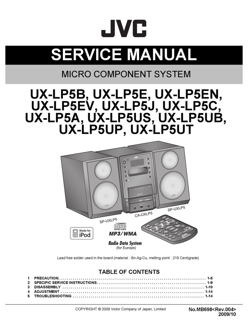
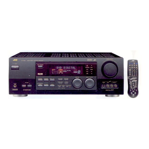
JVC RX-V7000UF User manual

SERVICE MANUAL
COPYRIGHT © 2006 Victor Company of Japan, Limited No.MB502
2006/1
AUDIO/VIDEO CONTROL RECEIVER
MB50220061
RX-V7000UF
Lead free solder used in the board (material : Sn-Ag-Cu, melting point : 219 Centigrade)
TABLE OF CONTENTS
1 PRECAUTION. . . . . . . . . . . . . . . . . . . . . . . . . . . . . . . . . . . . . . . . . . . . . . . . . . . . . . . . . . . . . . . . . . . . . . . . . 1-3
2 SPECIFIC SERVICE INSTRUCTIONS . . . . . . . . . . . . . . . . . . . . . . . . . . . . . . . . . . . . . . . . . . . . . . . . . . . . . . 1-4
3 DISASSEMBLY . . . . . . . . . . . . . . . . . . . . . . . . . . . . . . . . . . . . . . . . . . . . . . . . . . . . . . . . . . . . . . . . . . . . . . . 1-5
4 ADJUSTMENT . . . . . . . . . . . . . . . . . . . . . . . . . . . . . . . . . . . . . . . . . . . . . . . . . . . . . . . . . . . . . . . . . . . . . . . 1-14
5 TROUBLESHOOTING . . . . . . . . . . . . . . . . . . . . . . . . . . . . . . . . . . . . . . . . . . . . . . . . . . . . . . . . . . . . . . . . . 1-15
All manuals and user guides at all-guides.com
all-guides.com

1-2 (No.MB502)
SPECIFICATION
* : Corresponding to Linear PCM, Dolby Digital, and DTS Digital Surround (with sampling frequency -32 kHz, 44.1 kHz, 48 kHz)
Designs and Specifications are subject to change without notice.
Amplifier
Output Power At Stereo operation Front channels 100 W per channel, min. RMS, driven into 8 Ω, at 1 kHz
with no more than 0.8% total harmonic distortion
(IEC268-3/DIN).
Front channels 100 W per channel, min. RMS, driven into 8 Ω, at 1 kHz
with no more than 0.8% total harmonic distortion.
At Surround operation Center channel 100 W, min. RMS, driven into 8 Ω, at 1 kHz with no more
than 0.8% total harmonic distortion.
Surround channels 100 W per channel, min. RMS, driven into 8 Ω, at 1 kHz
with no more than 0.8% total harmonic distortion.
Audio Audio Input Sensitivity/Impedance (1 kHz) TAPE, VCR, TV SOUND/DBS, DVD:220 mV/47 kΩ
Audio Input (DIGITAL IN)* Coaxial DIGITAL 1 (DVD):0.5 V(p-p)/75 Ω
Optical DIGITAL 2 (VCR), DIGITAL 3 (TV SOUND/DBS):-21
dBm to -15 dBm (660 nm ±30 nm)
Recording Output Level TAPE, VCR:220 mV
Signal-to-Noise Ratio ('66 IHF/DIN) TAPE, VCR, TV SOUND/DBS, DVD:96 dB/62 dB
Frequency Response (8 Ω) TAPE, VCR, TV SOUND/DBS, DVD:20 Hz to 50 kHz (+1
dB, -3 dB)
Bass Boost +4 dB ±1 dB at 100 Hz
Equalization (5 bands) 63 Hz, 250 Hz, 1 kHz, 4 kHz, 16 kHz:±8 dB (in 2 dB
steps)
Video Video Input Sensitivity/Impedance Composite video:DVD, VCR, DBS 1 V(p-p)/75 Ω
S-video:DVD, VCR,DBS (Y: luminance):1 V(p-p)/75 Ω
(C: chrominance, burst):0.3 V(p-p)/75 Ω
Component:DVD, VCR (Y: luminance):1 V(p-p)/75 Ω
(PB, PR):0.7 V(p-p)/75 Ω
Video Output Level Composite video:VCR, MONITOR OUT 1 V(p-p)/75 Ω
S-video:VCR, MONITOR OUT (Y: luminance):1 V(p-p)/75 Ω
(C: chrominance, burst)0.3 V(p-p)/75 Ω
Component:MONITOR OUT (Y: luminance):1 V(p-p)/75 Ω
(PB, PR):0.7 V(p-p)/75 Ω
Synchronization Negative
Signal-to-Noise Ratio 45 dB
FM tuner (IHF)
Tuning Range 87.50 MHz to 108.00 MHz
Usable Sensitivity Monaural:12.8 dBf (1.2 µV/75 Ω)
50 dB Quieting Sensitivity Monaural:16.0 dBf (1.7 µV/75 Ω)
Stereo:37.5 dBf (20.5 µV/75 Ω)
Stereo Separation at OUT (REC) 35 dB at 1 kHz
AM tuner
Tuning Range 531 kHz to 1 710 kHz (at 9 kHz intervals)
530 kHz to 1 710 kHz (at 10 kHz intervals)
General
Power Requirements AC 220 V, 50 Hz
Power Consumption 200 W (at operation)
0.9 W (in standby mode)
Dimensions (W ×H ×D) 435 mm ×200 mm ×425 mm
Mass 11.4 kg
All manuals and user guides at all-guides.com

(No.MB502)1-3
SECTION 1
PRECAUTION
1.1 Safety Precautions
(1) This design of this product contains special hardware and
many circuits and components specially for safety purpos-
es. For continued protection, no changes should be made
to the original design unless authorized in writing by the
manufacturer. Replacement parts must be identical to
those used in the original circuits. Services should be per-
formed by qualified personnel only.
(2) Alterations of the design or circuitry of the product should
not be made. Any design alterations of the product should
not be made. Any design alterations or additions will void
the manufacturers warranty and will further relieve the
manufacture of responsibility for personal injury or property
damage resulting therefrom.
(3) Many electrical and mechanical parts in the products have
special safety-related characteristics. These characteris-
tics are often not evident from visual inspection nor can the
protection afforded by them necessarily be obtained by us-
ing replacement components rated for higher voltage, watt-
age, etc. Replacement parts which have these special
safety characteristics are identified in the Parts List of Ser-
vice Manual. Electrical components having such features
are identified by shading on the schematics and by ( ) on
the Parts List in the Service Manual. The use of a substitute
replacement which does not have the same safety charac-
teristics as the recommended replacement parts shown in
the Parts List of Service Manual may create shock, fire, or
other hazards.
(4) The leads in the products are routed and dressed with ties,
clamps, tubings, barriers and the like to be separated from
live parts, high temperature parts, moving parts and/or
sharp edges for the prevention of electric shock and fire
hazard. When service is required, the original lead routing
and dress should be observed, and it should be confirmed
that they have been returned to normal, after reassem-
bling.
(5) Leakage shock hazard testing
After reassembling the product, always perform an isola-
tion check on the exposed metal parts of the product (an-
tenna terminals, knobs, metal cabinet, screw heads,
headphone jack, control shafts, etc.) to be sure the product
is safe to operate without danger of electrical shock.Do not
use a line isolation transformer during this check.
• Plug the AC line cord directly into the AC outlet. Using a
"Leakage Current Tester", measure the leakage current
from each exposed metal parts of the cabinet, particular-
ly any exposed metal part having a return path to the
chassis, to a known good earth ground. Any leakage cur-
rent must not exceed 0.5mA AC (r.m.s.).
• Alternate check method
Plug the AC line cord directly into the AC outlet. Use an
AC voltmeter having, 1,000Ωper volt or more sensitivity
in the following manner. Connect a 1,500Ω10W resistor
paralleled by a 0.15µF AC-type capacitor between an ex-
posed metal part and a known good earth ground.
Measure the AC voltage across the resistor with the AC
voltmeter.
Move the resistor connection to each exposed metal
part, particularly any exposed metal part having a return
path to the chassis, and measure the AC voltage across
the resistor. Now, reverse the plug in the AC outlet and
repeat each measurement. Voltage measured any must
not exceed 0.75 V AC (r.m.s.). This corresponds to 0.5
mA AC (r.m.s.).
1.2 Warning
(1) This equipment has been designed and manufactured to
meet international safety standards.
(2) It is the legal responsibility of the repairer to ensure that
these safety standards are maintained.
(3) Repairs must be made in accordance with the relevant
safety standards.
(4) It is essential that safety critical components are replaced
by approved parts.
(5) If mains voltage selector is provided, check setting for local
voltage.
1.3 Caution
Burrs formed during molding may be left over on some parts
of the chassis.
Therefore, pay attention to such burrs in the case of pre-
forming repair of this system.
1.4 Critical parts for safety
In regard with component parts appearing on the silk-screen
printed side (parts side) of the PWB diagrams, the parts that are
printed over with black such as the resistor ( ), diode ( )
and ICP ( ) or identified by the " " mark nearby are critical
for safety. When replacing them, be sure to use the parts of the
same type and rating as specified by the manufacturer.
(This regulation dose not Except the J and C version)
Good earth ground
Place this
probe on
each exposed
metal part.
AC VOLTMETER
(Having 1000
ohms/volts,
or more sensitivity)
1500 10W
0.15 F AC TYPE
All manuals and user guides at all-guides.com

1-4 (No.MB502)
SECTION 2
SPECIFIC SERVICE INSTRUCTIONS
This service manual does not describe SPECIFIC SERVICE INSTRUCTIONS.
All manuals and user guides at all-guides.com

(No.MB502)1-5
SECTION 3
DISASSEMBLY
3.1 Removing the top cover
(See Fig.1)
(1) From the right and left sides of the main body, remove the
four screws Aattaching the top cover.
(2) From the top side of the main body, remove the six screws
A' attaching the top cover.
(3) From the back side of the main body, remove the six
screws Battaching the top cover.
(4) Remove the top cover in the direction of the arrow 2 while
extending the lower sections of the top cover in the direc-
tion of the arrow 1.
Fig.1
A'
A
1
1
2
B
A'
Top cover
All manuals and user guides at all-guides.com

1-6 (No.MB502)
3.2 Removing the front panel assembly
(See Figs.2 and 3)
• Prior to performing the following procedure, remove the top
cover.
(1) From the top side of the main body, disconnect the card
wire from the connector CN402 on the front board. (See
Fig.2)
(2) Disconnect the card wire from the connector CN201 on the
power supply board. (See Fig.2)
(3) Remove the wire protection board fixing the card wire. (See
Fig.2)
(4) Remove the four screws Cattaching the front panel as-
sembly. (See Fig.2)
(5) Remove the four screws Dattaching the stay bracket. (See
Fig.2)
(6) From the bottom side of the main body, remove the four
screws Eattaching the front panel assembly. (See Fig.3)
(7) Remove the front panel assembly in the direction of the ar-
row. (See Fig.3)
Fig.2
Fig.3
CD D
C
D
C
Front panel assembly
CN201
Power supply board
Wire
protection
board
CN402
Front board
Stay bracket
E
Front panel assembly
E
All manuals and user guides at all-guides.com
all-guides.com

(No.MB502)1-7
3.3 Removing the rear panel
(See Fig.4)
• Prior to performing the following procedure, remove the top
cover and stay bracket.
(1) From the back side of the main body, remove the strain re-
lief from the rear panel in the direction of the arrow.
(2) Remove the thirty screws Fattaching the rear panel.
Fig.4
3.4 Removing the component board and tuner unit
(See Figs.5 and 6)
• Prior to performing the following procedure, remove the top
cover and stay bracket.
(1) From the top side of the main body, disconnect the parallel
wire from the connector CN511 on the S-video board. (See
Fig.5)
(2) From the back side of the main body, remove the four
screws Gattaching the component board. (See Fig.6)
(3) From the top side of the main body, disconnect the card
wire from the connector CN1 on the tuner unit. (See Fig.5)
(4) From the back side of the main body, remove the two
screws Hattaching the tuner unit. (See Fig.6)
Fig.5
Fig.6
Rear panel
F
FStrain relief
F
CN511
S-Video board
Component board
Tuner
CN1
HG
Rear panel
All manuals and user guides at all-guides.com

1-8 (No.MB502)
3.5 Removing the DSP board, audio input board, DVD board and video board
(See Fig.7)
• Prior to performing the following procedure, remove the top
cover, stay bracket and rear panel.
(1) From the top side of the main body, disconnect the DSP
board from the connector CN481 on the front board.
(2) Disconnect the audio input board from the connector
CN421 on the front board.
(3) Disconnect the DVD board from the connector CN431 on
the front board.
(4) Disconnect the video board from the connector CN441 on
the front board.
Fig.7
3.6 Removing the S-video board
(See Fig.8)
• Prior to performing the following procedure, remove the top
cover, stay bracket and rear panel.
(1) From the top side of the main body, disconnect the parallel
wire from the connector CN511 on the S-video board.
(2) Disconnect the S-video board from the connector CN461
on the front board.
Fig.8
CN481
Front boardDVD board
Video board
CN421
Audio input board
DSP
board
CN431 CN441
Front board
CN511
S-Video board
CN461
All manuals and user guides at all-guides.com

(No.MB502)1-9
3.7 Removing the front board
(See Fig.9)
• Prior to performing the following procedure, remove the top
cover, rear panel, stay bracket, component video board, DSP
board, audio input board, DVD board, video board, S-video
board and tuner unit.
(1) From the top side of the main body, disconnect the card
wire from the connector CN402 on the front board.
(2) Disconnect the relay board from the connector CN491 on
the front board.
(3) Disconnect the wires from the connectors CN471, CN472
and CN473 on the front board.
(4) Remove the three screws Jattaching the front board.
(5) Loosen the screw Kattaching the front board.
Fig.9
3.8 Removing the speaker terminal board
(See Fig.10)
• Prior to performing the following procedure, remove the top
cover, stay bracket, component board and rear panel.
(1) From the top side of the main body, remove the solders
from the soldered sections aon the speaker terminal
board.
Fig.10
Front board
CN472 CN491
Reray board
CN402
CN473
CN471
J
K
J
Soldered sections a
Speaker terminal board
All manuals and user guides at all-guides.com

1-10 (No.MB502)
3.9 Removing the main board
(See Fig.11)
• Prior to performing the following procedure, remove the top
cover and stay bracket.
(1) From the top side of the main body, remove the solders
from the soldered section bon the speaker terminal board
attaching the parallel wires.
(2) Disconnect the relay board from the connectors CN291
and CN491 on the power supply board and front board.
(3) Disconnect the parallel wire from the connector CN241 on
the power supply board.
(4) Disconnect the wire from the connector CN251 on the pow-
er transformer board 1.
(5) Disconnect the wires from the connectors CN471, CN472
and CN473 on the front board.
(6) Remove the screw M, two screws Nand four screws Pat-
taching the main board.
Fig.11
3.10 Removing the heat sink
(See Figs.12 and 13)
• Prior to performing the following procedure, remove the top
cover, stay bracket and main board.
(1) Remove the ten screws Qattaching the heat sink of the
main board. (See Fig.12)
(2) From the reverse side of the main board, remove the two
screws Rattaching the heat sink. (See Fig.13)
Fig.12
Fig.13
N
P
Soldered
section b
Power
transformer
board 1
CN241
Power
supply
board
Wire
protection
board
CN251
Speaker
terminal
board
CN491
CN291
CN472
CN471
CN473
Front
board
Relay
board
P
P
N
M
Main
board
Q
Q
Heat sink
Main board
Heat sink
Main board
R
R
All manuals and user guides at all-guides.com

(No.MB502)1-11
3.11 Removing the center amp. board, front amp. boards (L/R) and rear amp. boards (L/R)
(See Figs.12 and 14)
• Prior to performing the following procedure, remove the top
cover, stay bracket and main board.
(1) Remove the ten screws Qattaching the heat sink of the
main board. (See Fig.12)
(2) Disconnect the center amp. board from the connector
CN321 on the main board. (See Fig.14)
(3) Disconnect the front amp. board (L) from the connector
CN311 on the main board. (See Fig.14)
(4) Disconnect the front amp. board (R) from the connector
CN312 on the main board. (See Fig.14)
(5) Disconnect the rear amp. board (L) from the connector
CN331 on the main board. (See Fig.14)
(6) Disconnect the rear amp. board (R) from the connector
CN332 on the main board. (See Fig.14)
Fig.14
3.12 Removing the power transformer
(See Fig.15)
• Prior to performing the following procedure, remove the top
cover and stay bracket.
(1) From the top side of the main body, remove the solders
from the soldered section con the power transformer
board 1.
(2) Remove the solders from the soldered sections don the
power transformer board 2.
(3) Disconnect the wire from the connector CN251 on the pow-
er transformer board 1.
(4) Remove the four screws Sattaching the power transform-
er.
3.13 Removing the power/fuse board
(See Fig.15)
• Prior to performing the following procedure, remove the top
cover and stay bracket.
(1) From the back and top sides of the main body, remove the
screw Tand screw Uattaching the power/fuse board.
(2) Remove the solders from the soldered sections eattaching
the power cord.
(3) From the reverse side of the power/fuse board, remove the
solders from the soldered sections fattaching the wires.
Fig.15
3.14 Removing the power supply board
(See Fig.16)
• Prior to performing the following procedure, remove the top
cover and stay bracket.
(1) From the top side of the main body, disconnect the parallel
wires from the connectors CN203 and CN241 on the power
supply board.
(2) Disconnect the card wire from the connector CN201 on the
power supply board.
(3) Disconnect the relay board from the connector CN291 on
the power supply board.
(4) Disconnect the parallel wire from the connector CN101 on
the headphone jack board.
(5) Remove the solders from the soldered section con the
power transformer board 1.
Rear amp.
board (R)
Front amp.
board (R)
Center amp.
board
Rear amp.
board (L)
Front amp.
board (L)
CN332 CN331 CN312 CN311 CN321
Main board
CN251
Soldered
section c
Soldered
sections d
Soldered
sections e
Soldered
sections f
Power
transformer
Power
transforme
r
board 2
Power cord
S
S
U
T
S
S
Power transformer board 1
Power/Fuse
board
All manuals and user guides at all-guides.com
all-guides.com

1-12 (No.MB502)
(6) Remove the two screws Vand the screw Wattaching the
power supply board.
(7) Remove the power supply board from the hook gof the
chassis base bracket in the direction of the arrow, take out
the power supply board.
(8) Turn over the power supply board, remove the solders from
the soldered sections hattaching the wires.
Fig.16
3.15 Removing the headphone jack board
(See Fig.17)
• Prior to performing the following procedure, remove the top
cover, stay bracket and front panel assembly.
(1) From the top side of the main body, disconnect the parallel
wire from the connector CN101 on the headphone jack
board.
(2) From the front side of the main body, remove the nut and
screw Xattaching the bracket (phones) to the chassis
base.
Fig.17
V
V
W
CN201
CN101
Headphone jack
board
CN241
CN203
Relay
board
CN291
Power transformer board 1
Soldered
section c
Soldered
section h
Hook gof the
chassis base bracket
Power supply board
Headphone jack board
Nut
Chassis base
H.P Bracket
X
CN101
X
All manuals and user guides at all-guides.com

(No.MB502)1-13
3.16 Removing the system control board
(See Fig.18)
• Prior to performing the following procedure, remove the top
cover, stay bracket and front panel assembly.
(1) From the back side of the front panel assembly, remove the
seven screws Yattaching the system control board.
(2) Disconnect the parallel wires from the connectors CN705,
CN707 and CN714 on the volume board, jog board and
power switch board.
(3) Disconnect the wire from the connector CN706 on the
switch board.
Fig.18
3.17 Removing the jog board, volume board, power switch board and switch board
(See Figs. 18 and 19)
• Prior to performing the following procedure, remove the top
cover, stay bracket, front panel assembly and system control
board.
(1) From the back side of the front panel assembly, remove the
two screws Zattaching the power switch board. (See
Fig.18)
(2) Remove the four screws AA attaching the jog board. (See
Fig.18)
(3) Remove the three screws AB attaching the volume board.
(See Fig.18)
(4) Remove the two screws AC attaching the switch board.
(See Fig.18)
(5) Pull out the volume and jog knobs from the front side of the
front panel assembly, remove the nut attaching the front
panel assembly. (See Fig.19)
Fig.19
AA AB
CN705 CN714
CN706
Jog board
System control board
Switch board
Power switch board
CN707
Volume board
Z
YY AC
Nut Volume knob
Front panel assembly
Jog knob
All manuals and user guides at all-guides.com

1-14 (No.MB502)
SECTION 4
ADJUSTMENT
This service manual does not describe ADJUSTMENT.
All manuals and user guides at all-guides.com

(No.MB502)1-15
SECTION 5
TROUBLESHOOTING
This service manual does not describe TROUBLESHOOTING.
All manuals and user guides at all-guides.com

(No.MB502)
Audio/Video Systems Category 10-1,1chome,Ohwatari-machi,Maebashi-city,371-8543,Japan
Victor Company of Japan, Limited
VPT
Printed in Japan
All manuals and user guides at all-guides.com
all-guides.com

SCHEMATIC DIAGRAMS
RX-V7000UF
Contents
Block diagrams
Standard schematic diagrams
Printed circuit boards
2-1
2-2
2-10 to 14
CD-ROM No.SML200601
AUDIO/VIDEO CONTROL RECEIVER
No.MB502SCH
2006/1
COPYRIGHT 2006 Victor Company of Japan, Limited.
Lead free solder used in the board (material : Sn-Ag-Cu, melting point : 219 Centigrade)
All manuals and user guides at all-guides.com

In regard with component parts appearing on the silk-screen printed side (parts side) of the PWB diagrams, the
parts that are printed over with black such as the resistor ( ), diode ( ) and ICP ( ) or identified by the " "
mark nearby are critical for safety.
All manuals and user guides at all-guides.com

2-1
Block diagram
IC403
IC402
SOURCE
SELECTOR
IC423
SELECTOR
IC428
6CH MASTER
VOLUME
Q315
Q317
Q206,Q208,Q209
RY302
RY303
RY203
RY304
IC427
IC451
RY202
Q202
IC551
IC552
SELECTOR
IC581
IC582
IC583
SELECTOR
T201
POWER
TRANS.
T202
TRANS.
D1301-D1304
D206-D209
+B2
-B2
D201-D204
Q203
Tuner unit
Audio signal input terminal section
Video signal input terminal section (S Video)
(Component)
Audio section
Volume / Regulator / Source select section
Speaker terminal section
Primary section
Primary
section
Primary
section
Primary section Primary section
Audio signal input terminal section
(Video)
Video signal input
terminal section
(DVD)
(Audio input)
IC501
SELECTOR
TU_CLK
TU_CE
TU_DATAIN
TU_DATAOUT
TUNER_L
TUNER_R
TU_MUTE
DVD_L
DVD_R
SIG_L,SIG_R
INPUT_ATT
VCROUT_L
VCROUT_R
SURR_L
SURR_R
CENTER
FL
FR
AM
FM
DVD_F
MONITOR
P
R
J591
AV COMPULINK
J406
SUBWOOFER OUT
CD
VCR_REC
TV_SOUND
VCR_PLAY
TAPE_PLAY
TAPE_REC
CN473 CN472 CN471
CN372 CN371CN373
Lch
Lch
Rch
SLch
Cch
(Headphone)
SRch
Audio
amp.
Speaker
terminal
DVD_C/SW
DVD_S
J404
DVD
Main
plug
SW_DATA,SW_CLK,SW_STB
Speaker 1
terminal
M.OUT
VCR PLAY
DBS/TV SOUND
VCR REC
DVD
MONITOR
DVD
DBS/VCR
Y
PB
PR
Y
PB
PR
Y
PB
PR
CN311
CN301
+56V
-56V
B+5V
S1
F1,F2
Audio amplifier section
(Power/fuse)
J1501
ST305
ST304
CN421
CN401
J402 J403
CN1
CN411
CD_L,CD_R
TAPEIN_L
TAPEIN_R
TAPEOUT_L
TAPEOUT_R
VCRIN_L
VCRIN_R
TV_L
TV_R
VCROUT_L
VCROUT_R
TUNER_L
TUNER_R
DVD_L
DVD_R
CN431
DVD_C
DVD_SW
DVD_SL
DVD_SR
SW_OUT
DVD_L
DVD_R
CN451
DVD_SL
DVD_SR
DVD_C
DVD_SW
SW_OUT
IC701
SYSTEM
CONT.
DI701
FL DISPLAY
Q711
AN0
to
AN6
ROM_WP
ROM_SCL
ROM_SDA
RY_LR1, RY_C
RY_S,RY_HP
POWER
DIGITAL_IN1
J681
DIGITAL_IN2
UN682
IC601
IC602
FILTER
DSP
IC661
IC667
CODEC
with S/PIDF
IC611,IC612
IC613,IC615
IC621,IC622
IC632,IC633
IC634
FILTER
DSP, CODEC
CONTROLLER
IC671
LIN+/-
RIN+/-
A1+/-,B1+/-
A2+/-,B2+/-
A3+/-,B3+/-
S727
IC673
D719
Q705
S742,S743
S745,S750
D710
to
D712
S731
to
S733
W706
CN706
W705
CN705
W707
CN707
STB_LED
AN1
AN1
LED_DIMMER
BLUE_LED
VOL_JOG1
VOL_JOG2
AN3
MULTI_JOG1
MULTI_JOG2
S721 to S724
S726
S734 to S739
SWITCH
SEG1 to SEG15
GRID1 to GRID16
IC704
EEPROM
JS702
JS701
(Function switch)
(Multi jog)
(Volume)
RX0
RX1
DIGITAL_IN3
UN683
RX2
SCK
(Power switch)
User control keys / System control
FL display section
Surround / Digital signal input terminal section
Q704
Q1427
Q1428
Q1429
Q1424
Q1425
Q1426
Q1421
Q1422
Q1433
AVCOMPULINK
VCR_IN
VCR_OUT
DSP_IN_L
DSP_IN_R
DSP.L/R
DSP.LS/RS
DSP.C
DSP.SW
CDIN,CDOUT
CCLK,INT
D_RST,D_CS
D/A0 to D/A3
DATA,MCK,XTAL
S_BCK,S_LRCK
C_BLK,C_LRCK
DSP_RST
SS,HREQ
MOSI,MISO
GPIO1 to GPIO4
CN683
DSP_CLK
DSP_STATUS
DSP_READY
DSP_RESET
DSP_COMMAND
TU_DATAIN
TU_DATAOUT
TU_CLK,TU_CE
VOL_CLK,VOL_DATA
VCR,DVD
CN702
CN701
CN681
CN481 CN482 CN402
Q316
Q318
Rch
CN312
CN302
Audio amplifier section
Q915
Q917
Cch
CN321
CN901
Audio amplifier section
Q815
Q817
RLch
CN331
CN801
Audio amplifier section
Q816
Q818
RRch
CN332
CN802
Audio amplifier section
J501 J502
CN441
CN501
Q504
Q505
Q501
Q502
VIDEO1
VIDEO2
AVCOMPULINK
IN2
OUT
IN3
IN1
J551 J552 J553
CN551 CN511
VIDEO1
DVD_S/C
VCR_S/C
VIDEO2
CN461
VIDEO1
VIDEO2
AVCOMPULINK
VIDEO1
VIDEO2
VCR
DVD
L,R
SL,SR
C,LFE
VOL_CLK
VOL_DA
S_MUTE
SW_MUTE
DSP_CLK,DSP_STATUS,DSP_COMMAND
DSP_READY,DSP_RESET
SW_DATA
SW_CLK
SW_STB
IN_L
IN_R
DSP_L,DSP_R
DSP_SL,DSP_SR
DSP_C,DSP_LFE
CN201
CN251
FW201
FW201
J101
CN101
FW251
CN203
FW303
CN241
FW341
CN351
FW302
FW302
FW301
FW301
FW501
SIG_L
SIG_R
FRONT_A
L
L
R
R
C
RL
RL
C
C_IN
R_IN
L_IN
RR
RR
RR_IN
RL_IN
CENTER
REAR
FRONT_A
CENTER,REAR
Q210
POWER
RY_HP
RY_C,RY_S,RY_LR1 HP_LHP_R
MICK
FW704
CN714
J503
DBS/TV SOUND
VCR1
All manuals and user guides at all-guides.com

2-2
Parts are safety assurance parts.
When replacing those parts make
sure to use the specified one.
Standard schematic diagrams
Primary section
RY_LR1
POWER
RY_S
RY_C
RY_HP
PROTECTOR_IN
POWER
PROTECTOR_IN
RY_S
RY_C
RY_HP
RY_LR1
BIAS
330p
C102
330p
C101
CN101
QGD2504C1-03Z
1
2
3J101
QNS0022-001
1
2
3
470
R102
OMF
2W
470
R101
OMF
2W
CN241
QGD2504C1-05Z
1
2
3
4
5
Q210
KRC105M-T
EP1
E409182-001SM
GND
CN291
QGB2510J1-04
1
2
3
4
CN492
QGB2510K1-04
1
2
3
4
CN292
QGB2510K1-04
1
2
3
4
CN203
QGD2504C1-05Z
1
2
3
4
5
Q206
KRC105M-T
D218
1SS133-T2
FW201
QUM217-14Z4Z4-E
1
2
3
4
5
6
7
68 R210
UNF
RY203
QSK0109-001
456
12 3
FW251
QUM213-08DGZ4-E
1
2
3
Q208
KRC105M-T
Q209
KRC105M-T
10
R208
UNF
D212
1A3G-T1
2200/6.3
C213
D219
1A3G-T1
D220
1A3G-T1
CN201
QGF1205C1-14
14
13
12
11
10
9
8
7
6
5
4
3
2
1
PW307
820
R204
UNF
1/4W
10
R203
UNF
1/4W
Q205
KTC3200/GL/-T
1/50
C218
D217
MTZJ8.2C-T2
100K
R209
FW201
QUM217-14Z4Z4-E
1
2
3
4
5
6
7
0.1
C203
0.1
C202
0.047C207
0.047C206
2200/35
C204
1000/35
C205
0.1
C201
D202
1A3G-T1
!
D203
10DDA20-FD
!
D201
10DDA20-FD
!
D204
1A3G-T1
!
Q203
KTC3203/OY/-T
Q202
KRC105M-T
D207
1A3G-T1
!
D208
1A3G-T1
!
470/25
C209
D206
1A3G-T1
!
D209
1A3G-T1
!
D211
MTZJ6.2C-T2
D210
1SS133-T2
470/16
C212
0.0047
C210
!
T202
QQT0478-002
!
9
54
1
CN251
QGA3901F2-03
1
2
3
RY202
QSK0128-001
!
21
43
PW104
PW205
PW204
PW203
0.0047/100
C208
2.2
R201
1/4W
UNF
PW105
EP201
QNZ0136-001Z
PW101
PW103
PW302
TA201
TA202
PW102
!
R221
10
UNF
1/4W
C221
470p
!
!
!
!
LVA10209-6
+B2
FRONT_A
FRONT_B
REAR
CENTER
HP_L
HP_R
(1/4W)
GND
FL-B
5.6V
5.6V
F1
-VPP
F2
B+5V
+B2
-B2
HP_L
HP_R
T201
LVA10209-13
LVA10464-6
LVA10209-7
LVA10209-8
LVA10209-9
to FW303
(LVA10323-2)
to FW341
(LVA10323-1)
TO CN491
(LVA10464-1)
to CN701
(LVA10464-2)
TH.FUSE
S3
S3
S2
S2
COM
S1
S1
COM
(100V)
(100V)
(100V)
POWER
TRANSFORMER
D.GND
A.GND
F205
T100mAL
F201
T2.5AL
F202
T2AL
F203
T2AL
114
112
110
111
113
121
120
122
130
131
010
012
013
NC
NC
-24.0V
-31.0V
-24.0V
0V
4.9V
5.0V
AC220V 50Hz
HEAD PHONE
QQT0507-001
230V
220V
0V
MAINS
PLUG
!
!
!
!
!!
!
!
!
!
!
!
All manuals and user guides at all-guides.com
Other manuals for RX-V7000UF
1
Table of contents
Other JVC Receiver manuals

JVC
JVC RX-778VBK - Audio/Video Receiver User manual

JVC
JVC KD-X38MBS User manual

JVC
JVC RX-5022VSL User manual

JVC
JVC RX-5042S User manual

JVC
JVC KD-X482DBT User manual

JVC
JVC KD-X362BT User manual

JVC
JVC RX-5042S User manual

JVC
JVC RX-DV3RSL User manual

JVC
JVC LVT0100-001B User manual

JVC
JVC RX-7VBK User manual

JVC
JVC RX-8020VBK User manual

JVC
JVC RX-DP10VBK - AV Receiver User manual

JVC
JVC KD-X470BHS User manual

JVC
JVC EXAD KW-AVX820 User manual

JVC
JVC RX-772VBK User manual

JVC
JVC RX-8012VSL User manual

JVC
JVC KD-X120EE User manual

JVC
JVC KD-AVX1 User manual

JVC
JVC KD-S675 User manual

JVC
JVC RX-6020VBK User manual