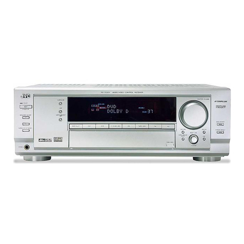
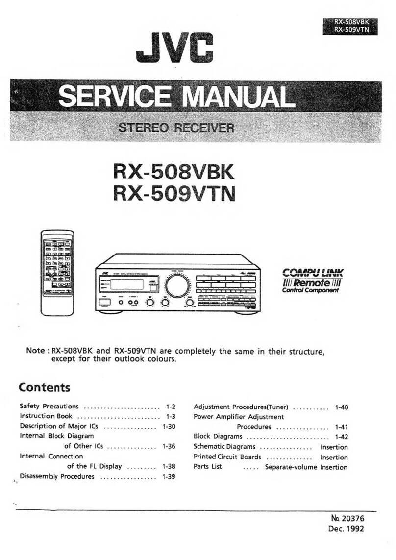
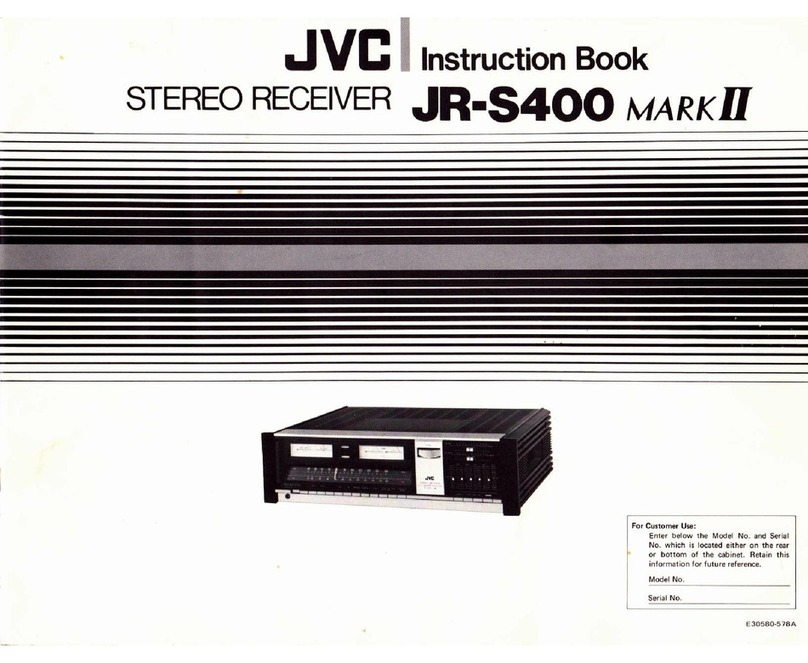
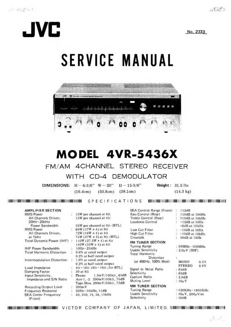
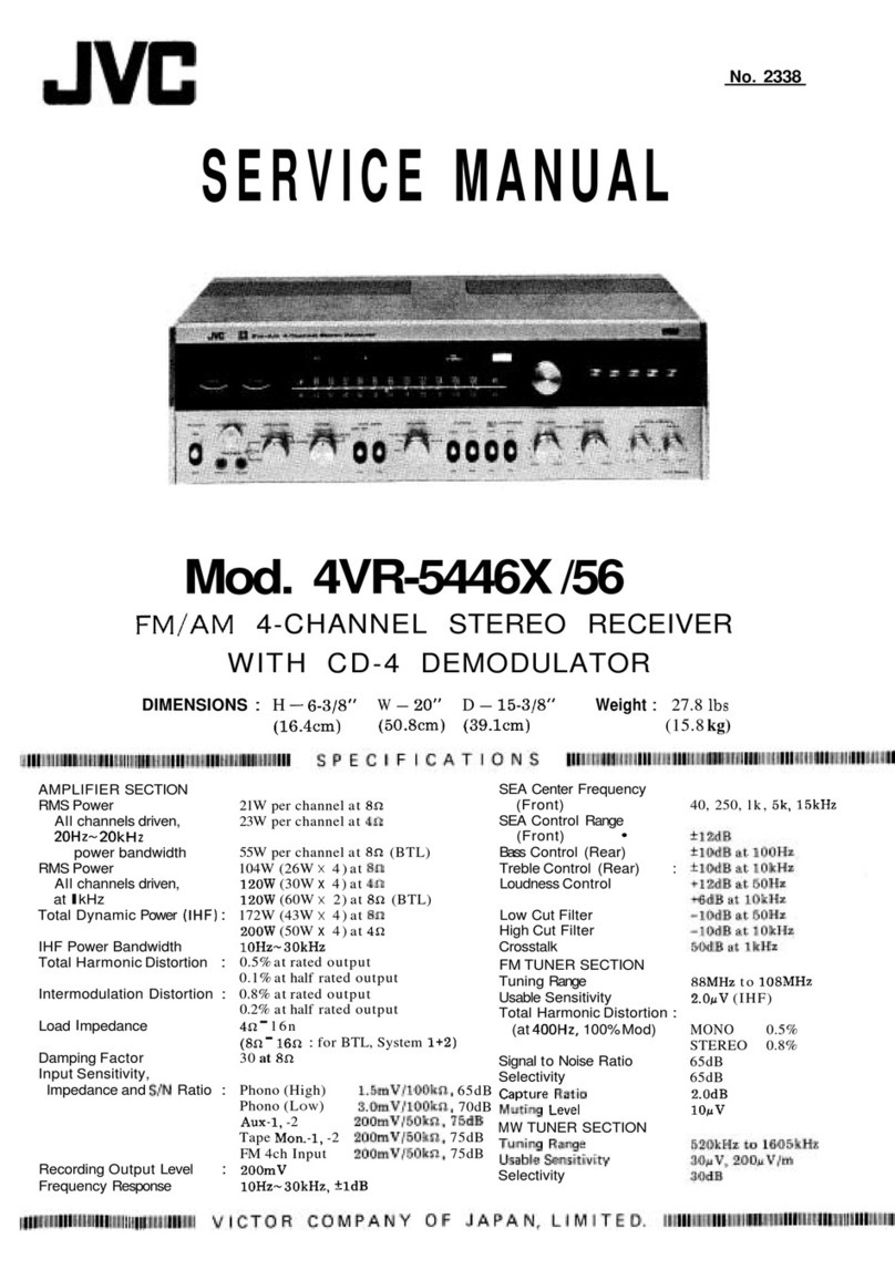
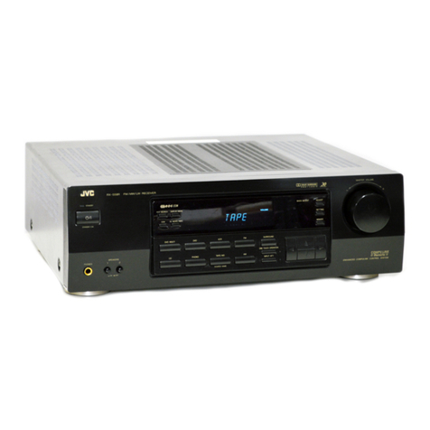
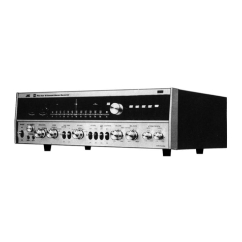
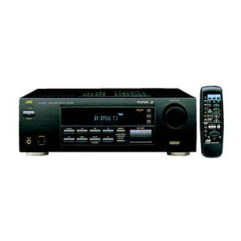
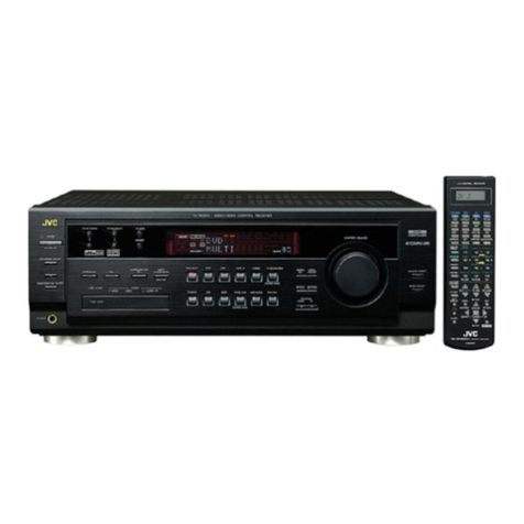
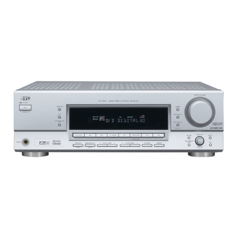
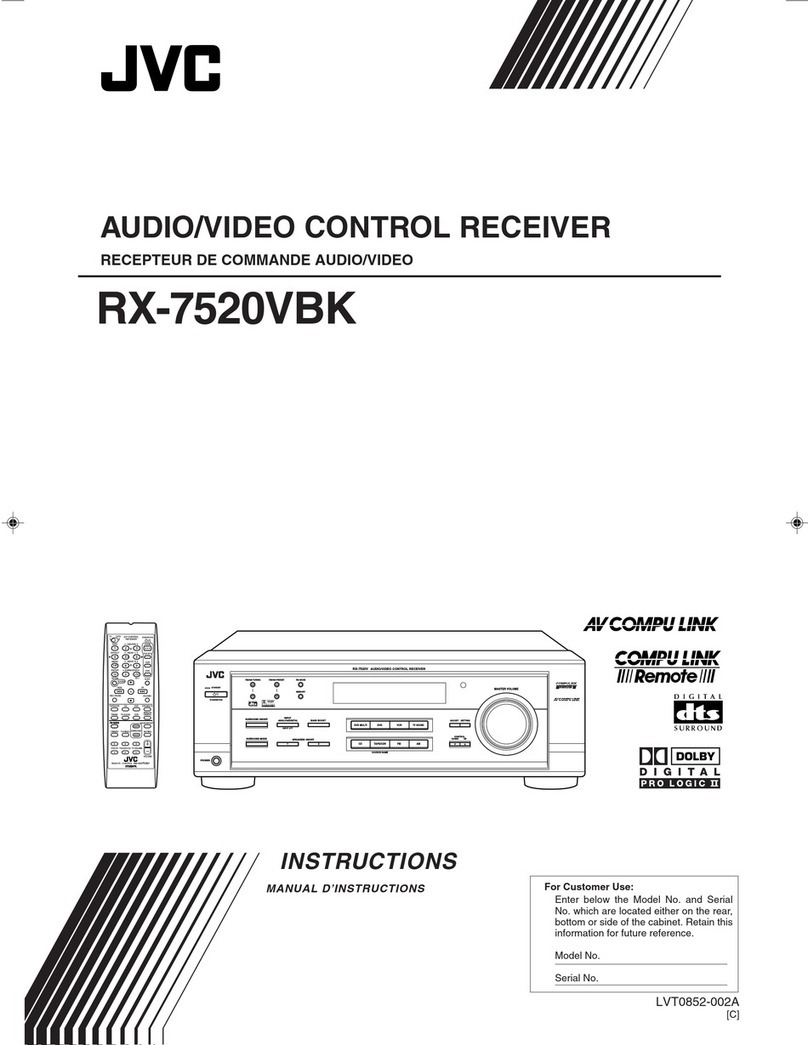
JVC DR-E34BK User manual

DR-E34BK
DR-E34LBK
JVC
SERVICE
MANUAL
STEREO
DOUBLE
CASSETTE
DECK
RECEIVER
DR-E34BK
MODEL
No. DR-E34LBK
"
~ -
-----
-
." •..a
-
-····•-"!'
- . ;
_____
·-
€
1-1
! >
1-1,
::.w,,-:o
,:-l
<
l•l
:-c-
l-l
Contents
Page
Safety
Precautions
.......
.
..........
....
.
..
.
..................
1- 2
Instruction
Book
........................
..
......................
1- 3
Disassembly
Procedures
................
..
................... 1-16
Explanation
of
System
Control
IC
....
.
...................
1-17
Description
of
Major
I
Cs
.....................................
1-
18
Explanation
of
Other
I
Cs
.....
.
..............................
1-23
Internal
Connections
of
the
FL
Display
Tube
...
..
....
1-25
Adjustment
Procedures
(Cassette
Deck)
...............
1-
26
Page
Adjustment
Procedures
(Tuner
)
.....
..
.....
.
.....
..
.......
1-29
Connection
Diagrams
.........
.
.............
...
....
.
......
.... 1
-30
Schematic
Diagrams
....
....
.
......
...
..
.
..........
.
...
.. In
sertio
n
Printed
Circuit
Boards
.....
..
......
.
......
..
....
.
..
.
....
.
Insert
i
on
Block
Diagrams
..
...
.
..
.
......
.
...........
..
......
...
.....
.
In
s
ertion
Parts
List
............
.
....
.
........
..
Separate-vo
l
ume
Insertion
No.
20162
Mar
.
1990
www.audiodna.sk

DR-E34BK
DR-E34LBK
-Safety
Precautions
------
---
------,
1.
The
design
of
this
product
contains
special
hardware
and
many
circuits
and
components
specially for
safety
purposes.
For
continued
protection,
no
changes
should
be
made
to
th
e original design unless
authorized
in
writing
by
the
manufacturer.
Replacement
parts
must
be
identical
to
those
used
in
the
original ci
rcuits.
Service
should
be p
er·
formed
by
qualified
personnel
only.
2.
Alterations
of
the
design
or
circuitry
of
the
product
should
not
be
made.
Any
des
i
gn
alterations
of
the
product
should
not
be
made.
Any
design
alterations
or
additions
will
void
t
he
manufacturer
's
warranty
and
will
furt
h
er
relieve
the
manufacturer
of
responsibility
for
personal
injury
or
property
damage
re
sulting
t h
erefrom.
3.
Many
electrical
and
mechanical
parts
in
the
product
have
special
safety-related
character
istics.
These
characte
ri
stics
are
often
not
evident
from
visual
inspection
nor
can
the
protect
i
on
affo
r
ded
by
them
necessarily
be
obtained
by
using
replacement
components
rated
for
higher
voltage,
wattage,
etc.
Replacement
parts
which
have
these
spec
ia
l
safety
characteristics
are
identified
in
the
Parts
List
of
Service
Manual.
Electrical
components
having
such
features
are
identified
by
shading
on
the
schematics
and
by
( 5 )
on
the
Parts
Li
st
in t
he
Service
Manual.
The
use
of
a
sub-
stitute
replacement
which
does
not
have
the
same
safety
characteristics
as
the
recommended
replacement
part
shown
in
the
Parts
List
of
Service Manual
may
create
shock,
fire,
or
othe
r
ha
zards.
4.
The
leads in
the
products
are
routed
and
dressed
with
ties, cl
amps
,
tub
ings,
barriers
and
the
l
ike
to
be
sepa
rated
from
live
parts,
high
temperature
parts,
mo
ving
parts
and/or
sharp
edges
for
the
prevent
ion
of
electr
ic
shock
and
fire
hazard.
When
service
is
required
, t he original lead
rout
ing
and
dress
should
be
observed,
and
it
should
be
confirmed
that
they
have
been
return
ed
to
norma
l,
after
re-ass
embling
.
5.
Leakage
current
check
(
Elect
rica
l
shock
hazard
test
ing)
After
re-assembling
the
product
.
always
perform
an
isolation
check
on
the
exposed
metal
parts
of
the
product
(antenna
terminals
,
kno
bs.
metal
cabinet.
screw
heads,
headphone
jack,
con
trol
shafts,
etc.)
to
be
su
re
the
product
is
safe
to
operate
without
danger
of
electrical
shock.
Do
not
use
a li
ne
iso
lation
transformer
during
this
check.
• Plug
the
AC
line
cord
directly
into
the
AC
outlet.
Using a
"Leakage
Current
Tester",
measure
the
leakage
current
from
each
exposed
metal
part
of
the
cabinet.
particularly
any
exposed
metal
part
having a
return
path
to
the
chassis,
to
a
known
good
earth
ground.
Any
leakage
current
must
not
exce
ed
0.5
mA
AC
(r.
m.s.).
•
Alternate
check
method
Plug
the
AC
line
cord
directly
into
the
AC
outlet.
Use
an
AC
voltmeter
having 1
,0
00
ohms
per
v
olt
or
more
sensi-
tivity
in
the
following
manner.
Connect
a
1,500.Q
10W
r
esistor
paralleled
by
a 0 .
15µF
AC-type
capac
itor
be
-
tween
an
exposed
metal
part
and
a
known
good
earth
g
round.
Measure
the
AC
voltage
across
the
resistor
with
the
AC
voltmeter.
EE3
AC
VOL
TMETEA
(Hav
i
ng
1000
ohms
/
volt.
or
more
sensitivity.)
t)
0--
-
..
Move
the
resistor
connection
to
each
exposed
meta
1
part,
particularly
any
exposed
metal
part
having a
return
path
to
the
chassis,
and
measure
the
AC
volt-
age across
th
e
resistor
.
Now
, reverse
the
plug in
the
AC
outlet
and
repe
at
each
measurement
.
An
y
vo
ltage
measu
re
d
must
not
exceed
0 .
75
V AC
(r.m.s.).
This
corresponds
to
0.5 rnA
AC
(r
.
m.s
.).
i Place
this
prnbe
__
_.__...__
_,,""'
_ _
___._--<
•• on each exposed
15000
,o w
metal
pan.
~
Good
eanh
ground
Warning
1.
This
equipment
has
been
designed
and
manufactured
to
meet
international
safety
standards
.
2. It
is
the
legal
responsibility
of
the
repairer
to
ensure
that
these
safety
standards
are
m
ainta
in
ed.
3.
Repairs
must
be
made
in
accordance
with
the
relevant
safety
standards.
4.
It is essential
that
safety
critical
compo
nents
are
replaced
by
approved
parts
.
5.
If
mains
voltage
selector
is
provided.
check
setting
for
local voltage.
1-2 (No.
20162)
www.audiodna.sk

Schematic Diagram
■
Tuner Section
(1
l
Notes:
1
i==J
2.
3.
4.
FOR
[
..,
.,.,
""
Shows
DC
vo
ltage
to
the
chassis
with
no
signal
input
.
indicates
+8 p
owe
r
supp
ly.
indicates
- 8
power
supply.
i
ndicates
signal
path.
5.
When
replacing
the
parts
in
the
darkned
are ( - ) and
those
marked
with
~
, be sure
to
use
the
.designated
parts
to
ensure
safety.
6.
This
is
the
standard
circuit
diagram.
·
The
design
and
contents
are
subject
to
change
without
notice.
DR-E34BK
DR-E34LBK
(No
20162)
www.audiodna.sk

DR
-
E34
BK
DR-E34LBK DR-E34BK
DR-E34LBK
■
Tuner
Section
(2)
CM)
~
LEV
UM.DI
RI
GQ
181(
f8K
~1s
,.
,t;2
l2
CK
120<
R
t6316'
3.9K
3.
9"
R\65
.1
11t1
na,c
2'IQr.
R
16"1
'
"'
,,,.
R
l96
2.....
2<11
8198
8.21<
8-
21(
C160
•o• 22
01'
en,
0.
1122
~
c
m.
ne -
SFIOI
~
UEl
FE:101
EH'"Z203-
oo,
~_.J!L
-
FM
A
I.JTO
J'()
'5
I
GNAL
1-'/,1
t-.o
SIGNAL
L
I/
N)
SIOW..
'-
-
--
- - -
--
- - - - - - - -
--
- - - -
---
-
--
- -
--
--
---
-
__
.++-1-+-+-+-!h
"
°'
----
- - - -
--
--
--
----
W..
:.,.
--
-
--
TO
EK
-
013
'0
ffil-036
~
~
:§
jl
:§
EAF2203-001
r-----------------------------------
--
--~
I
~
I
I
II
.
Cl
I
I
R7
'·
"'
01
·00:
ISV
\03
C4
•
1----<1
~
...
...
m
'--+--
----IL-----1
- -
-1
-....----.-......,,--+e'
·
.:.:""::....{ss)
••
Cl>
•
~
re'f
,
~J~
I
'--------.-.......10,
I
I
I
I
= I
I I
L------
------
---------------
-
--------
---
~
iFw'\0\1 1J
-.IO
LI
• ..J «
EAF2203-002
r----------
-
-------
---
----------
------
--
-
---,
I
TR1
I
!
~
I
I
---
--
~-----11-
--
.-u
t
I ~
1--
-
-<
]~
~.
--
- - ~ u -
02
L3
l
..
...
R3 £
0,C
l<\.
.
-'--+--'--+--J._J___.....,_____Ji--4----..J-
......
-l
_::
'0
:::00<:.j.:.:=.,_...____..1;
•
;!.l
,
~"'~....J:=+--+-.-,
.......
-
--1--
~ ~
VI
s,\-
----1
--
---1
--
----le-
- -
-+---
--1
iI
I
.,.
Notes:
1.
Shows
DC
vo
lt
age
to
the
c
has
sis
with
no
signal i
nput.
rndicates
+B
powe
r
supply.
5.
When
replacin
g
the
parts
in
the
dark
ned
are
I - ) a
nd
those
marked
wit
h
.&.
, be sure
to
use
the
designated
parts
to ensure
safety.
2.
3. i
ndi
cates
- B
power
suppl
y.
6.
This
is
the
standa
rd c
ir
c
uit
d
iagram.
4 .
indica
t
es
sig
nal
path.
The
design
and
conten
ts are
sub
j
ect
to
change
wit
h
out
not
ice.
(No.
20162)
(No
20162
)
www.audiodna.sk

■
Cassette
&
Power
Amplifier
Section
r----------------------------------------------------------------------------------
Notes:
1.
2.
--
3.
---
4.
lm
ai
1 -
1 1
$
Shows
DC
vo
ltag
e
to
the
chassis
with
no
signa
l
input.
indicates
+8
power
supply.
indica
tes
- B
power
supply.
indicates
signal
path.
I
I
__
_
__
.
____
_.
---
AL~
19)
FOR
WEST
8ElllWfY
- ii
~SOI\!
\'Cl.
TASE
SELECTOI!
LOCATIOH
,
700
0 0
I .
L'=
~:::::::=~==~
'..__
_
_J
LJ
~AA,~~~A>,..A~,._,.,'-A.
•---.
...,.__...,._
,
._.....
A,'.
.J'l'
"'1
_ _
--
-------
---""
.
..
.
............
. _ .!!•
~
......
.....
~~~PPFPFi
rrrfiF
JiirFlijrf
,
~J
~ot,Ufl.lre
C.I
.H
..
1031
Flll>4
•
F'WN
U
TO
&C·O'r.llRIQn
C,.
IJ,
11-M,10tl
5.
Wh
en
replac
i
ng
the
pa
rts
in
th
e
darkned
are
( - l
and
those
marked wi
th
Lt.
, be sure
to
use
the
designated
parts
to
ensure
safety
.
6.
This
is
the
standard
ci
rcuit
diagram
.
The
de
sign
and
contents
are
subject
to cha
nge
without
notice
.
DR-E
34BK
DR-
E34
LBK
(
No
.
201
62
)
www.audiodna.sk

SEA
&
System
Control
Section
DR-
E348K
DR-E3
4LBK
OR-E34BK
DR-E34LBK
w
-..or:
~ !l
:
_:
~~
~-
~
L
t==t
::t:::::::
~
=::
~~~~
~~~[
-----rr.
-~-
-;-
---_-_-_-_-
_::_
-_-_-
_+1-_-_-_-_-_-
_-_-
_-_
-_
~_-_
{1-_-_-+f_-_-_-_-_-_-_
-
..::f1-_y
-
---
--
---
--------
..........
..
>--+-'.,__+-""
!':
L
___
lml
_ r!l!5)
_l!!i§J
_
,1§1
I
I
I
'r
~
~-"T"""-----
----
--~
----......._
u
USED
-··
~"
~,
"'
'
/OE
""'
r
;a;;
..
..
..
...,
.
.
LOI
U.U,Ji>
l..._..
OCH.
..,.,
..,., ..,.,
/OE
.,,.,,
use,
ICM
'-'El
"""
use,
r--
I
I I
I I
I I
I I
I I
I I
I I
I I
'
----------'
--------
--
~
§~
I
"- ~
t ~
"" -;
~.
o -
'"'
~1:~
'D
-
~- '
"""
t
~·=
~
iii
I
---------------~
I
I
I
I
,--------
-------------------
---
------------J
..
r:.N....B.-10
1
-11
_- - - - - - - - - - - - - - - - -- - - - - - - - - -
_J
'
""
..
I
I
L
__
___
__
•-te:>14
....J
------
l>W.l.
rt
--7
""
""
I
I
,
.....
I
I
M
L
________________
______
_____________
_
Notes:
1.
2.
3.
4.
Shows
DC
voltage
to
the
chassis
with
no
signal i
np
u
t.
ind
ic
ates
+B
power
supply
.
indicates
- B
power
supply
.
indicates
signal
path.
5.
Wh
en
replacing
the
par
ts
in
the
darkned
are I - l a
nd
those
marked wi
th&.
, be sure
to
use
the
designated
parts
to
ensure
safety.
6.
T
his
is
the
sta
ndard c
ir
c
uit
diagram
.
The
design
and
con
te
n
ts
are
subject
to
change
without
notice
.
(No.
20162
)
!No
.
20162
)
www.audiodna.sk

Printed Circuit Boards
■
Tuner
PC Board (ENA-
094
)
A-
099
)
OR-E34BK
DR-
E34
L
BK
(No.
20162
)
www.audiodna.sk

■
Cassette
SW
and
Power
Primary PC Board (ENB-
101
l
roo
t • z
0
(/)
-
w
l/)
:,
LL
DR-E34BK
DR-E34LBK
(No
2016
2)
DR-E34BK
DR-E34LBK
(
No
.
2016
2)
0
I '
www.audiodna.sk

■
System Control and
FL
Display PC Board
(ENC-073)
DR-E34BK
DR-E34LBK
(No.
20162)
www.audiodna.sk

[
■
Cassette and
AMP
PC Board (
ENJ-036)
DR-E3
4B
K
DR-
E34
LBK
(No.
20162)
DR-E34BK
DR-E34LBK
(No.
20
1
62)
www.audiodna.sk

Block Diagram
■
System
Control
&
Audio
Section
BALA
NC
E
FU
NCTION
SW
~~
PHONO
EQ
AMP
SE
A
AM
P -
,-::0-.
IC
281
~ V
.J
l
~
IC45I
111
52
18LR
,
IC452
~
Ff
lOM
CD
MAI
N
EN
N
217
1
(
~
I CD
--
BA38I2L
I MU
TE
I
0581~0583
/ ~
W201
F
FROM TUNER
EN
A-0
99
-1
1E
NA
-
09
4-11
JA
TO TUN
ENA-
09
IENA-
09
ER
9
41
D
103
FW
IOI
FWl05
TUNER
0--C
TAPE
~
' -
v--
IC581
I I
TC
9163N
AHEA
D~
l
PB
H.s.D
5
~s1NG
I
PB
A:B SW
lo20,.0202
IC201
t
I
RE
CiPB A
.•
B I
S HE
AD~
I HE
AD
SW
0271~0273
REC
PB
0203,0204
......
l ~ BIAS
!B
IAS TP I )• ADJ.
BI
AS
OSC
ERHEADq
-l
L335
I
BEAT
CUT
I
0335
~
0338
5335
®-H
SP
EED
CONT I MO
TOR
COU
NT
R255,
R256
I
0251~0253
A
DEC
K DRI
VER
:\o1
ECH
A
0541,
0542
0545.0546
~
®-H
SPEED
CONT I MOTOR COUNT
R265,R266
I
Q261-Q263
B
DEC
K D
RIVER
ME
CH
A
Q543,Q544
I0'-47,
0!'14A
-
TUN
ER
CONTROL
IC
401
LC6
5148
-
4245
J
1 1
r
U ONLYI I
TUNER
CON
T.
KEY
SW TUN
ER
DISPLAY
5401
5418
FL401
D403
D414
I
SE
A CO
NT
ROL
t~-ttf-
63 2
50
l K 4K
16K
R451,-.,
R460
I
PB MUTE N
R.
T.P.
0585-0587
PB
AM
P PB1
11:
PB
OU
T-
IC202
I
~PCl228HA
t t DOLBY
PB
MUTE
PB
EO
SW
rBL
E
VELi
NR
0221-0224
0225---0
0275,0276
IC381
'
%~74
---
R221~R224
HCl213
6A
I
RE
C
AMP
RE
C A
EC
-
I
IC301
l 1 O
UT
IN
t
~VI
A
~.
I R
EC
EQ
SW
11
REC
MU
TE 11REC L"EVEL
0305
,_,
0312
0367,0368
R366,R367
I ALC I
0361~0366
0369
NA
NR
R
EC
-
I
DE
CK CO
NT
I NR CO
NT
rl
VO
L. MOTOR
KEY
SW
0508
DRIVER
5952~5966
0509
IC503
rl
p
I D
ECK
INOI
CA
TOR I O
FF
BU
FF
.
0952
~
0957
Q503
)
TUNER
RE
S
ET
SYSTEM
CON
TR
OL
-
Q401~0403
---
IC501
0402
H06
1
408
1
S8
47
i
I
DCS
1/
0
MAIN
VOL. POWER
AMP
RYOOI
1
--
SPEA
KE
R
qr
TERMI
NA
L
I I
COOI
I
I STK 4 141V
I I
I I
I
----------,,.
~
HEAD
I I
/\
I . . PHONES
@ I
..
PROTECTOR l
I
'------
I
C002,
0002
.,_
____
_J
000
1~
0003
TO POWER
AMP
t t t
D051
~
D054
I 1
_
P.
OFF CONT r-~-~
'L~
'/
0003,0006
< '
RY002
P.
OF
F CONT
0066~007
1 ~4 -
D073
-
85V
REG
URATOR
Q051
,-.
Q055
-5
V
0055
~
---
""'
005
7---
0063
-
--
I
± 12V
0066
,0081 -re59,D560 I
±l
OV
,.....
0396,u.:r.:i
;
--
Q
-
30
V 0061~
0064
+ 6.8V
D066
~
0072
FL2
I
+
J1Y._
D08
1 FL I P.OFF~
0064,
I
009
::
H
0092
11
;;--vIiDC
OU
RES
ET
0502
TO
CO FRO
ENN-217 NT I
FW401
CD
INH I I
RECEIVE
D/STANDBY I
SOU
RCE
SELECT
SW SOU
RCE
INDICA
TOR
I INDICATOR
S521~5526
D52
1
~0525,
Q~7
D505
~
REMOTE CONT.
IC502
s
DR
-E
34
BK
DR-E
34
LBK
!No. 20 1
62
)
www.audiodna.sk

■
Tuner
Section
ATIOI
FM75fi
T102
LW
ANT
FE101
FRONT
END
PACK
FM
+8
Q125,Q126
L.P.FIL
TER
0113
0112
LW
RF
AMP
MW
RF
AMP
w} w}
1-
15
Q103
BUFFER
~
DR-E34BK
DR-E34LBK
CF101
C.
FILTER
~
DR-E34BK
DR-E34LBK
Q107
IF
AMP
~
T104
LW
DSC
D!
D!
T103
0108
BUFFER
CF102
C.
FILlER
~
~
Ql
14,0115
AM
OSC
SW
MW+B
LW+B
MW
DSC
IC
102
PLL
I~
~
::I!
IL..
(.)
(/)
0
I-
:I:
::>
<CO
24
IC
104
FM
DET
&AM
~
I-
0
u...
I-
u...1-
w
~
(.9
-::,
-
::>
0
~o
:::1:0
(/)
c(
(.)
X
I- I-
(/)
::>
B
0
~
3E
!:!::
0
I-
:::E
::>
2z
:::E
~
<O
<-
<
20
AM+B
0106
D
120
J 1
01
,
MUTE
SltREO
,mmr
4
CE
a..:
DO
...J
CK
~
I- I-
::>
::>
7
DI
0 0
Low -Poss
AM
+8
J8103
........
____
_,
...,__----,._, T
101
MW
ANT
,._
___
___,
Filter
+12V
--
+5
.
0V-----1
+12V
+5.0V
~---+---+-------1
3 L
OUT
SW202
LW+B
9K
___.1
OK
F\4+8
MW+B
LW+B
0121,0123,Ql24
J
105
K2
D7
To
SYSTEM
CONTROL
(ENC
-
07
3-1)
(No. 2
01
62
) (No.
2016
2)
Llll,Lll2
C
203,C204
C
20l,C202
IC
105
MPX
GND
ROUT
TO
SYSTEM
CONTROL
(ENC-073
-
·I
)
FROM DECK
AMP
(ENJ-036-1
l
www.audiodna.sk

Instruction Book
CONNECTION
DIAGRAM
0
AM
l
oop
arr.enr.a
AM-
Rahn\enR'1tenne
Antenna
ii
OOUGie
AM
AM-raaman•B<1~
Anttl1\B
de
cuadro
de
AM
AM ra
'l1
d!ller'ltt
",
M exte
maf
ar.:el'\na
AMAullenan:e1me
Ar~enne t1':ll!m<t
AM
l\M-o.,1Ienan1enne
/\r'll,ef\d
exui,,o,
de AM
Jtornl"lu5
At.'1
tc1r'1
e11
n
FM
external antenna
U
KW
Aullenan.:e<11
"'nleMe
ex!E!f!le
l'M
FM
-bu~enanie,,r,e
A,1ena exteno•
oe
r-
v
Utomhur. FM
anteM
For
W
Germany
.
Sw,ul)fland
and
"6
v
"'ur
Bunoe!i'l!Pt.r~•
Deutr.1
:lll"J S
Cf1w,.~z
uno
Ila n
"a;
r r
A~nagne
de
OlAl!il
·a
S,J,sse
Cl
I mr-e
Voor
W9Sl-0....tsland.
ZY
, •scr1and e~ tlal o
orua AJe,,,.1,-1
0o.;od8<"11a
Su..za
v
l'J'
~
F1,
VJs111y-.Jd.ui<1
~w.
• och a'f'n
DR-E34BK
DR-E34LBK
..,.
_____
....,._
kc
ma
:r
"'-1
'eeder
runen.
na
uKW
-Spe,sean:wirl!?
Fee
der
d
9"'1ill>('I
L!
FM
H,
'·>'0G<>11,JSill'!tlnrll!
A.,t.,,"1
de
a,
mootaoc
·
o,.
FM
rv
'11a:a:'lr'e-n,,
I
,
___
--
----------
0
~
--
--
--
-
-~-
1-
~
•
[i]
.
i
:
'
'
"-
•--
-
•·
I
I
I
..
----
-----7--------------
--
__
___
__
_.
•
f1erno1
e
cable
Fe<nbe<l·ell"<dbel
CAb.,,
t?
:e,!aeo-r.mande
,v,·
~'l(!Sl)ea_e~
ngs,ca~
C;iOie
oe
ma
n
do
a
d1S1anc,a
Ff<1!rstyrtngskabe!
8
£x!erMI
AN
TE
N
NA
terrnInals
9 Exte
rrt'al
ANTEN
"-1
1\
lc:Jrmnil'ill (for W.
Germ
a·
ny
, Sw
otzer.ancJ
e.11Cl
ltal•(!
9
PHONO
lemirnal
s
8 V
I0!:0/AUX
rorm<nai.:i
e
CD
temur.als
Cl
CO
MPU
l:
NK-2/SYN
CH
RO terminals
• DC OU1PUT lOlfll\11,;a
Co
meet
1"'9
l)tope,
I,,mIabie as
nd,ca:ec
at
e~l1
lerrn,,,.'.I..
0 SPEAKERS ce,rmina's
9
BE
A- CUT
"n
ob
N
or
l'l"'IIIY sel lo .,
..
(
See
F g. 1
0,
page 5)
e
AM
ch
annel
spa
cing
noo
·
(See
·1 p
age
9.)
• Volt.age
~QI
·
Wh
en
ll"lrsequrpmenl
,,
useo
lr
an
area
whe
re
lhe
sup~
vof~
,s
d,t•e-er>l
horn
lhe
i;ireset
volta
ge. resat
:hoe
,
'Ollage
S81oclo
·
to
rna COf·
rec
,pos1h0n
Not
pr
ov,oed
•
o,
the
U K • Austruha
Bild
C-Oo·
1m!l'l'!l
al
[u
rope.
• P
OW!l
' (Xl(O
Notes:
1.
Connect
the
speaker
cords
correctly;
L
to
Land
R
10
A.
2.
Switch
the
power
ott
when
con
necting
any
component.
3.
Connect
plugs
or
wires
firmly.
P
oor
con-
tact
may
result
In
hum.
4.
Use
speakers
w
it
h
the
correct
Impedance
.
The
correct
impedance
Is
I
ndicated
on
the
rear
p
ane
l.
(l)
f''
t
~
1,111
;
I
i
_
_____
_!
(No 20
162)
1-3
www.audiodna.sk

DR-E34BK
DR-E34LBK
ANTENNAS
~____,
~;,,
~
Lb.1
Afb.
1
How
to
set
up
the
loop
antenna
.
Montage
der
Rlngantenne.
Comment
monter
l'antenne-cadre
.
lnstalleren
van
de
raamantenne.
C6mo se
lnstala
la
antena
de
cuadro.
Sa
satts
ramantennen
upp.
AM
Antenna
How
to
fix
the
loop
antenna
(Fig.
1)
• Install the ~n,
en
na
by
n
se
r.
ng ,1i
11
U1u
c.
ie
c-
lion of lhP
ar
row
. (S
e<>
F,g. 6)
• P
lace
ar
ii
d,stilnce trom
lhe
oowur
sour
ce
c-o<d
,;q1IIIcoroandmtJUh
M1..
,es
or,
'
h"
=
body
'"
11
SOO
I
Wie<II
r
ecepl.JQn
IS
9000
.
AM (MW/LW)
loop
antenna
(Fig
. 2)
Th,
s antenna is t
or
rhe r
ecep
tion of
loc
al
AM
broad
c
as
t.
AM (MW/LW)
external
antenna
(Fig
.
2)
ii
AM
1ce-0p1
,on
-s.
u
nsat
:s1dCtory co
nr,ec
:
an
ex-
ternal
AM
m~c
rw:,a
(Stngte
,w
e
an
tenna)
10
1ne
AM
antenna terrn
1nal.
Noise
and
Interference
(Fig.
3)
C
h.ar.g
e !he
o,ec"o
n
ot
the
IOo
:J
ante!'l'la
o,
re,n-
st
~
n a
be:ler
posa•,on
wtw:>n
r
ec
ept.on,s,
(),sy
.
Notes
:
• If
the
provided
loop
antenna
is
not
con-
nected
,
It
will be
impossibl
e
to
receive
AM
broadcasts
.
•
When
In
s
talling
an
external
AM
antenna
,
l
eave
the
AM
loop
antenna
connected
.
FM
Antenna
How
to
set
the
FM
antennas
Antenna
term
i
na
ls
ditter
according
to
the
markets.
Atter
checking
up
your
set
,
select
the
con
-
nection
method
out
ol
@,
®
or
©.
@ Fig. 4
How
to
co
n
nect
the
coaxial
'..!
. &r p
oi
l
lhe
sheath
to
exPOSE
:
he
l:Yo,d
:,bo,.n
20
mm {13116"
).
f
Open
thobr
.-
d 10 ex
po&e
111e
co
'1d
:x:
tor
ar,out
tOrr
'Tl
(7116 ').
·3
P.i'il tl-e
co
nduc:
or
"1
1D
lhe FM A
NTE
NNA
te
rm,naJ
.
• Tape, oti
•i,c
b<.i,d
and
plug ~
-,,10
the
G
NO
Ie
r
rn
,
r111I.
FM feeder antennas
P
lu
g
111
10
Ille
FM a
nte11n;,
ter:n,nal.
$
Fig
. 5
• Tne
l'M
1,
u!
antl!11na
pro...oed
ea
~
be
con
f!!C'ed
I.Oa
75-ol"
TICDa.Xlal
jacl<
a;
aI
P.mP'l
rn
ly
'
rnea
su
1e
• 75-o'lrn
ar:c
nna wi
ll,
coaxial iy
pe
co
nn
ector
{DIN 45 332) shou:c be
conneded
•o
111e
7
5-
omn
rer
rr.
,r..;
1-4
(No.
20162)
*
Fig
. 2
Abb
. 2
Afb.
2
Fig.
4
Abb.
41
Afb
. 4
i
nse<1
1:--e
arro.v
part.
---
!:
....
_7 l
,.
-
.1
·
=t-
. - _,
"':2-
I -
--
~
..
~
:--
.-•
'-
~
,-:
"'
·:-
. -
D
en
mi1 o
,n.im
Pie
d
oo
w,
::t
nC!
en
~ ~
0111st
eck
en
tnserer la par•,e llechee.
Fig
. 6
Abb.6
Alb
. 6
S!eek
!l
ei p,,1--gedee;e
'138
' ~
~nnen
tnser.e
IR
par;e
de
la '
le<;hA
Sa,1 ,n
den
p-mar
k:a
aeien
.
Fig. 3
Abb
. 3
Afb
. 3
\ Fig. 5
Abb
. 5
Afb
. 5
www.audiodna.sk

ij
2
4 ~ -
r
C,
Fig.
7,
Fig
. 8
•
How
to
connect
the
FM
connector
In
case
of
a
75-ohm
antenna
(Fig.
7)
C
1.
Open
Ille
claws
ai
bolt! :-desa
nd
1cmo11e
1he
COV
!l'f
.
2. Cul
botr!
el'l(js
ot
1he
cord andlllmOV\!
IL
(
OIV\I
when
1r.1111g
C-OO
'<'
.al
cable)
3. F •
Ille
ooax,al c:ablO 0'ld ~s
core
4.
Put
on
1he
c(M:lr
In
case
of
a
300-ohm
antenna
(Fig.
8)
n,
na
neoessat)
to
remove
the
CO\'er
rtne w
re
rfli;lde -s
cut
JOO
ohm
a,,_er,,...
ca
'l
not be used
Notes
:
•
Choose
antennas
to
meet
the
reception
co
nditions.
•
Or
i
ent
and
tlx
antennas
where
audio
reception
is
the
clearest.
1
J'
(i
\..
:v
~~
·'>• ~ '
I
3
L
-
.-·r,,N-
I~ \-
-ct
.~
.f.
.~
~~,~
_,
1
Fig. , ~
~
r
Abb.7
L ·
Alb.
7
How
to
connect
cords
(Fig.
9)
1.
00c
n
a111
1:m
IClrll< 1ul '""'--'S
~
Piwg
cords
n10 1
'1
8 10
r1cs
,J
(.;IOS<!
,li
e levtlrll
BEA
T CUT
knob
(Fig. 10)
WN!n reoord
:n
g
ifl'I
AM
l!,IW:
LW)
b,oadca:;:_
ooa~
m
a~
·
ccc.u
•
5ef
me
8EATCUT
.rico
loca!:9d
o,
11n
e
rc
'>l
' pariel
Lo 1··
c,r
' 2· .0
bEra16
wH
:ie
a
"11
1
f\i!led
C
..
...
,.,..,
DR-E34
8K
DR-E34LBK
F
ig
. 8
Abb.
8
,.__
__
___
_ _;:;_ _ _
__,
Afb. 8
I
r1.:c
~•~1
\
11.:~
11L"1r11mls
1
,1
Ill
:-them I s
l>J
• II
,I
ii
\\
\\\
II\:-~·,,
it"CJll
,lf
ll
l d
.it1
I
C1
il!~r Q,1
.....
...
~
~
Fig.
9
Fig
. 10
'-
A.bb. 9 -
Abb
.
10
Alb.
9
Alb
.
10
(No.
201621
1-5
www.audiodna.sk

DR-E34BK
DR-E34LBK
H
ow
to
use
10
KEYS
To e
nt
er
1
lo
10
: Simply p
ress
the !!pP
fCJllr1a
te
Hoe
1o Key-toet.sen gebrulken
0m
1
!al
lO
in 18
vo
eren·
~
.--
----~
num
l!llc
key, D
ru
k
ge
~n
op de
gepas
1e ci
jf
ertoetsen.
0m
11
of
tioge
re n
um
mers in
te
voeren:
l=.Cl.:...L...:
How
to
use
the
remote
control
un
it
• To use
t.M
rl!f1'IDl
e
po,nc
4 at the REM0
1E
S
ENSOR
sect,on
an
1he
ms.n
un~
•
The
remole "
'Ofl<s
up
to
.abotJ1
7 m
apart
(This d
1G
ta
nce
ma
ybe reo
uce
d ,fy
ou
op
e·
ate
ii
SJOOiong
j
Hoe de
atstandsbealenlng
gebruiken
•
0m
de
alstaf'dsbedlM1r-.g
1e
getlrukB'l
mo8!
u
die
na
ar de R
EM
OTE ~
'E
NS
OR
op
hel
ap-
paraa
• l
1ch1en
•
De
a~anclsberneni
ng
we
1kt
l°'
1),1)
eer1
afsUlnd
v
311
or,go,;eei 7
n,
(Oeza
arsiand
J.a
r
kJdlnOf
w
orden
alGu
hi!!
ka.;;1!'8
Y.ai"I.Jll
-scillllnepo.
SlJB
Op
00
91
msot
r;
C:,,
I )
Note:
•co
remote
control
operation
la
poealble
only
when
a
JVC
COMPU LINK
CD
player
hM
been connec:ted
to
this unit by
connec:ttng•
remote
cable between
the
SYNCHRO
lennlnala
ol
both units.
Opmertdng:
• Afetl!nd8beclenlng van
de
komp
■
kt
tlsll~lsenkel
mogelllk---
JVC
komplllt1
dlekepeleronel
hit
COIIPU
LINK
■
yeteem
ungelloten
la
op
di
tONlaldmlr.Nn~
bel
tu
■■
en
de
SYNCHAO-aanslultl11941n
van
beta
toeste
lla
n.
1-
6 (No
201
62)
1o enter 11 or
hl!;Jhm
l'Uflbe1
s:
U
ae
the
.,
+ 1O"
ke
y.
E
xaniples
15:
P,1159
"+ 1D.' i
he11
pr
ess
"5 "
20: P
ress·
+
10
," 1hen press
"1
0
.'
25· P
re
~ + 1
0"
1
.w::
e.
th
en pu~ s
..
5."
4
0.
Press
..
+
10
" thr
ee
imea. 1
"1~
p;-~
10'
Benutzung
der
Tasten 1 -
10
~be
de
;
ZahJen
.,
u,
1
ll!S
to
11nfadl
dulch
~
de:
erup,~
Zi,Nerm
en
E"
~
de
Za
li
11
ode· ht\na!!r
Zahle-n
d
u/Ch
D,
ud.M
~
1'as!
e - +10".
Be
,s
poele
15:
Ta
Sle
..
+ 1
0"
..-id
ati
nn
Tast
e
"5
llruCl<.
en
20
: r
as:
e · + 10·· u
nd
dam
Tasts
"10"
dn.,c
ke
n
25.
Tasi.
e
..
.+,
10 ;iweunaJ
und
dam
Ta.sle
5"
d
ruc
ke
'l
4
0·
T ste " + 10-· d1e,mal
und
"8nn
Taste
· 10"
drucken
Utl
lisetlon
des
10
touches
De
1 /l 10: II s
u'
d'
appu
·
tar
su1
la
loua:ie
co
rrespo
n
da
fll
e.
Au
dela
de
11.
Appu
y
ez:
su1
La
tour.he T
10
.
E.·<Bm(jeS'
15: A
ppu
ye,
su
1..+10
~
sur
"5"
.
20
.
Appu
)'!IJ ' + 10"
puls
-lil.<I
"10'.
25:
Appu
ye,
..
~
10·
pui
s
..
~
10·
pu,
s sur •·s .
40: A
opuyer
+
10
... ' +
10
',
,t.
10
"
P1J11
sur
"I
0"
P.!c.
Ge
br
~ de
..
-+
1
0"
•toets.
V
oo
r
bee
l
den
15· Dr
uk
op
·· + 10 ·
en
di111
op
"
5"
.
20 D
ruk
op"+
10"
en
dan
op
" 1
0".
25 D«Jk
tw
eem
a
al
op " + 10"'
en
dan
op
"S
"
40
DruJ,;
ar
iern&31
op
..
t ,a·
e11
d$n
op
..
1o"
Como
utlllzar las tecles
numeric••
Para
I
nt
r
od
u
C11
un
yalor c
cmpr
andio
!lulHt 1
y
,o.
Pu!se
simi;;ernence
las teclas
r&1
m ricas
o
port
1.1
nas
Para
llllroducir
un
,
aJo
r
de
I 1 o
superior
.
U
11
l
lce
e1
bQ!On + 10
Eiemplos:
l5
Pu
,;e
"..,
!0'
y.
tlesplles
'5
".
20
: Pulse ··
+10•
· y, de
spu
es
"1
0".
25
.P
u.bi
' •
10"
~
vec
e5
y, despu
es
'5
4
0-P
~
•10
ttes
vecesy.
des
pues
"
lO
Anvllndn
l
ng
ev
de
10-tangent
F
Or
art
Nia
In
1 lill 1I: l
fl,ICI<
bMa
00
Onsl<s
d
:anger(.
F<>r
au
sialla
In
tal h
Og
re a,,
11
· Anv4nd +1o.
Ex
enpi,I
15: Tryc~
..
+
10"
oc
h
sedan
"5 '.
20
1ryck ' + 10"
och
secmn
"10
".
25
Tryck " +
10
"
tv
~
~f\08
1
oct,
sedan
•
·5
'.
.io
Tryck
~
1o tre
gAngor
oc
h s
ooo
n 1o '.
Fembedienung
•
Die
Ferr,oedie!'-lng
avf
de
n
fERNSENS
OR
oos
COSf;iif':le!S r,ch
te
n.
•
Das
Ge,at
kann
~
zu
eotlOOI Absland
von
7 m
m1I h ,ili)
OU
Fe•n
be
Ollll"llngbotllti
gl
wer
d
e,i
(°'8
Fe,ntledicoung
nict1I scht'ag
au
l
de
n
Sen
sor
r,c!Yen
.
Oaidurch
li&in
dts
Rciichweile
\/Cl•
ku
,n
wU1de1
1J
Manipulation
de
la
tele
c
ommande
!
eleccJn"fT'.ande
ne
peut
a
11•
q1,es elie est
0
11
ge
e vers la
pan,
e receptnce
de
l'ao
pa
re,I
QU
elle
dOOI
commander.
Mod
o
de
empleo
del
mando
a
dla
t
ancla
•
Paro
usar
Ill
manda
a d,S!anela,
din
haeIa
el $E
NS
OR
DE
CO
N
TRO
L R
EM
OT
E
oe
l;i
1.,ru-
d
ad
pr
nap.al
.
•
El
marw;lo
a
ostnt1CIa
1,
ene
un
1aclio
dP.11co<in
de
uoos
7
mmr
o~
.
(Esta<IS!aroa
~
sarmanorsu!!t&dopera
desQil
un
p0SK:,On
la1PraL
)
HIIINI
■:
• CO-Fembedlenung
l•t
nur
m6gllch,
-nn
eln JVC COMPU LINK-CO-Player
per
Frnbedlenk
■
bel
(Anachlul
en
die
SYNCHRO-BuchNn
balder
Oerlte)
en
dieN
■
Gertt
■
ngeechlouen
let.
Not
■:
•
La
operac
i
6n
de
control
,-mote
del
tocacllacoe compac:to Mio n poelble
CUllndo
..
conecte
un
toc:
■
dllCOI
CD
COMPU LINK
de
JVC •
eat
■
unldlld
medlanteun
cabledem
■
ndoa
dlet
■
nct
■
entni
loll
tennilielN
SYNCHRO de
embM
unldee
.
•
La
po
rt
ee
de
la
lo!CCQL'""nlande
attOll'lt
en111ron
7 mblres mam cello d•starce
dl'\1'41nt
pll.lS
cou
rte
vous n·oies
~
bien
datls r
ax
e
Hur
du
envllnder
fj
iirrkontrollen
• Nat
dlJ
an•,arider
IJankOl1trOllen
sk.a5
du
nKla
denna
mo&
hovudenhet£!f15 F.IAR
RSE
NSOR.
•
Fflurkon•rQIJe<,
lung
e
,a
r p6
upp
,~1
~
meters
aVS1;\nd
,a..t 1
ramfrAn
.
RemarquH:
•
LafollCtlol
■
..-ntde1616camn1
■
1
1deCD
n·•poee1111e
NUIIIIIIIII
..
un
lec111Urde
dlaque
aucllonunMrtque
JVC
COMPU
LINK
•
61'
l'ICCO~
• m apparel! en
branchenl
un clble de
~•
entni
In
bomH
SYNCHRO
de
■
deux
apparella.
Anm.
•
C[Hpelarena
flltmymlng
bllr
m6jllg
end
■
lt
etter
■
nllutnlng
11r JVCe
coi.
PU LINK
CD-lpelare
tlll detlll receiver•
dick
genom
■
It
.,,.,11111
~
beln
IMll
■
rl
aynkroultagenSYNCHRO
pi
recetverdlcket
och
CO-epeleren.
www.audiodna.sk

AM
@
I~
t
~
..
n
Cl
,n
ILi
~S
EIG
13:r
a
-
EIG
STn9 ffi
PAUSE
0m0
kHz
6
..e
·
~
111
3
~
I tL'C
~,ce
111.intli:ils
<
ir,111
ch1.:m
·s
I>iciHl(li
hy
H
,,
\\
lr
·t.:~c,,
l
cL!111am
1
.1
I
~.info
Use
th,s Insr
ruc11
on
oon
,
"-ee.M
q this
oag,
open
Die
vomege
,
ide
A
l'Ullung
ai,I
Seel
au
':..i:Hilgenunool!en
bemnleg
e.,_
U1diser
ce
manu
d'u
•d1s
at1on
en laissant cene p;!l;Je ouverte
Klap
deze
bi;.-
~
t •
<lO.)fi
eze" , an
de
Ql!f"'
uik
i;aarm,17,nq
Ulilice este
rr
1irLI!
de
instruciciones. ma
t'len1
endo
esl
a pai;iina atl,t!r:a.
A
..a
nd
den
n
:a
bruksar
.
~"'
·
O"'
h
dan
upp
- g ·
DR-E34BK
DR-E34LBK
(No.
20162)
1-7
www.audiodna.sk

DR-E34BK
DR
-E
34
LBK
OPERATION WITH
THE REMOTE
CONTROL UNIT
How
to
use
CD/TUNER
10
KEYs
TUNER
10
KEYs
1. P
re
f.5
TUNER
b11:tc
n (!)
2. P
re
s 10 KEY
s.
• If
you
h
t1~e
pt
esela
Slil!tQl'I,
you can IUoe1!
<rt
nstan•
y
by
press
ng
!he
p,c
S61
cha
il\l'ICI
nurnbel'
(Prese
ts
aie
porlo
rmed on
t11e
,-nam
unit.
See
page
10.)
CD
10 K
EYs
1.
Pre$S
CD
10
KEY
a.
tan
f,
2.
Pr-
10
l<EYs
• T
r.
10
KEYs
.,,
WOik
as
CD
10 KEVs,
g1v-
1
ng
you
ran
d
an
access
10
you,
favorites
(](I
a CD
.O.lso
ulil!d
ID
~·ary
!he
-eng:h
cl
131'.le
Clt.,r,ng
ea·
recording
How
to
use
CO
cha.nger
• Use tnis
Wllefl
()tlefBI
ng co
3UIO
_cl1an
ger
1.
Press •r
,u
CO
ehanqe
r BVTTO
!)
2. Select CONT
INUE
8
or
Pf'IGM
(gJ
bu:to,,
and
p,ess
11.
3.
Using
D
IS
C S
ELEC
T
(D]
-{fil)
button
,
specify
the
disc
n
umbe
r.
Note:
•
When
specifying
a
song
number,
use
AUTO
SEARCH
(
....
)
or
(l+f)
button
,
or
CO
10
KEYs.
•
Also
read
carefully
the
Instruction
manu
·-
al
of
the
CO
a1,1to
changer
.
Instructions
for
Use
ff
POWEA
- • T
urn
ON
1n
e rn
we
rto
lhe
marn uri.t tir
IGC
II
st
arod
by.
FADE
MUT
l
NG
•
Soo
tile VOLIJME
t:11
31
for a lower
.oun
rl
volume, dep01',o.ng
on
l
'IO
wm3rlylimes
yo..r
pr
ess
t111s
t;r.rnon
]::
VOLUME
[TI
: Press10 IOCR!llSP. t
he
SOI.Ind vollJlTle.
[ ".:°"' : P
re$$
to
reduce
·
he
SOIJnd vol
ume
.
©
TUN
EA
•
Pr
ess lo
UJ"fl
""'o QtOacJcBS
l~
by
U8I11g
t
he
10
Kl:.Ys as
TU
NER 10 KEYs
(5 CO
10
KEY
- • Press
:o
us
e the 1O KE.'(s llS
CO
10
KfYr.
.
;5;
CO
/TU
NER 10
KEY$
(
OJ
-
GID
, + 10 )
· •
Tna
10KEYs can beu
sed
11
s TUNER
or
CO
10
K€Ys
.
DISC
SELECT
(
[1
1 - L6] ) (CO
auto
changer
only)
• Press it ,
vll
eo
specily,ng a
l'.!tsc
numbGf ot
CO
il,\,l[O
ch
a
nge
r
J>
CO CHANGER (CO
auto
changer
only)
• ToQCefate CO
11uto
ci,ange
r press
rh
,s bul-
to
n
111$1.
.i)
CONTINU
E
(i
(CO
auto
changer
on
l
y)
• Press
to
play CO
com,n1,10
usty.
PRGM
[[]
(CO
auto
changer
only)
• PlaysCD m prngrntNTlc.d
or
oer.
'
9'\
CO
controls
~
CO .
►
..J
: Sli!rts
~ymg
!l
dlSC
STOP
Lii ]: Stops olayi
r¥J
a
oisc.
AUTO
SEARCH
I~ : Scans a
<>se
baci<·
ward.
AUTO
SEARCH
{m:
Sca
ris
tJ
dJsc
for-
ward.
• O,sc are
5CoMed
coot.nuou
s.y
t1105e
buttons are pressed
co
nun
u
ouGly
1-8
(No.20162)
@ D
ECK
A
CONTROL
►
: P
la~•s
•ape.
: Stop ta
pe
-4-4
: Fast-w
1nc1S
a :
ape
to
tne
tell
~ j : Fast-w
ind
s a :aQe
tO
the
r,gi
l
~
DECK
B
CONTROL
[,-
J:
Pl
a
ys
the Iron!
$<
de ot a tap
e.
W : Play$
1"'8
reverse
s,de
of
a tape.
RE
~ •~ : To
s.1an
ll!pe
r
ec
0td
il
'IQ
pre
ss
Iha
◄
or
._,
bu!lon
wt-le
haoclng
o:JWT1
this button.
• Mt,lilng
LS
operat::tlF.
from
the
main
-.1
rn
PA
US
El
[
ii
: Paui.e
pta
y
bat.11
or reco
rd
·
ll"IQ
• Pr
tlSS
tn.s
bu
tton
and
ltle
AE
C Ol
bv
llo
n
et
the
same time
10
einer 1NI
~EC
PAUS
E
mDC
!e
• To
re
k or recorcl.tig
pie,;s
!he
..>::::::J
bu~on
The
[ -
611d
.::J
wHons
ope,a
te
1t.e
same
as
th080
In DECK A CONTROL.
Source
selector
controls
111
P
HONO
Press to s:
e<i
10 a r
ecord.
(;,
AUX
P
1cu
10
<Sten
10
rn
e sound 1rom the source
p
lugg
ed
,mo
1t
e VIDE01AUX jacil.
DESCRIPTION AND
FUNCTIONS
Tuner
section
•
MEMORY
indicator
•
TUNED
I
nd
ica
tor
9 STEREO
Indicator
8
FM
/
AM
Ind
ic
ator
"F
M
or
··AM' ',glirs
~
3:1
i'M
or
AM
l)(oa
d-
cast
15
oe.119 rece
,..,
ed.
e
Freq
ue
nc
y/
channel
Jndicato
r
T
t-.s
1rodi
c.a1o
r
i'10<m
11
lly
6/lOW!,
a
freqL
-eacy
.
ll <ils.ola~ a
ct,
a11
ne]
AUrnber
'ht!e<l
PAESET
SCAN bl.il!Oll I~ pr
P.Ssod
\I/hen a 10
KE:Y
(pre;e:
st.1t1ons)
1s
pr&SSed,
ii
O;Spiays
a
r:har>
n
et
nu
mber
1or
a
oo
ut 2
$8Cond5
a
nd
r~
u
rn
s
10
a Ire(! e
rc
y
(k;f;:llny
.
8
MEMORY
8
AUTO
MEMORY
0
TUNING
(UP/DOWN)
Use
1.0
tune In an FM or AM broadca
st.
(See
·2,
page 9.)
UP
: Useto.ncr
emen1
lhel1Jf1e0-in
'
reQUency
DOWN
: Use ,o decrement
[!le
Wned· n
tr
e-
qucncy.
0 FM
•
AM
(
OR
-E34BK) AM (MW/LW) (OR-E34LBK)
• 1O
KEY
s
(Preset
stations)
See "
How
to
use
10
KEYs
,"
page
6.
•
PRESET
SCAN
Amplifier
section
•
POWER
(ON/STANDBY)
Furns,rc
po
wer
ON or aa,•,a;es
1~
STAN~
BY
mode.
STA
N
DBY
mode:
Pr
esel data ,s ,,;tair.ed
in
mem
ory
wr 'e t
:-,
e
po
we,
c
ord
1$
pl,
.'9!J8d
1r..o
si,
AC
011
tle· If a
oo
wc1
1a11Y
re
o:x:urs
or
tJ"ie
oord
1s
vnp,ugoec
u
ata
,5
rorH
illed
:o
r or,e
or
two
oays
be'or
e
me
mory
,~
cleared.
Note:
• A
small
amount
of
power
(9
watts)
is
con-
sumed
In
the
STANDBY
mode.
To
switch
the
power
off
completely,
unplug
the
power
cord.
e
Source
selectors
and
Indicators
TAPE,
PHONO, TUNER, CO,
and
VIDEO/
AU
X
•
PHONES
Jack
P
lug
re
aOphones
Into
this
Jack.
Note
:
•
Plugging
In
headphones
switches
off
the
sound
from
the
speakers.
•
REMOTE
SENSOR
lnrs
sensor
~91TIII
s,gr'lr!ll
strarumt:&dfrom
t
il
e
rem
ote conlrol
un,1
• RECEIVED
Indicator
L
qr.t
s ll;t'ler
It
~ or •'8Ce1\111Ssignals l•arsm,
r-
iei:1
•rom i
he
r
noce
contrc>'
1,;nc
POWER
ST
ANDB
Y
ind
i
cat
or
Lrg'11
-.~ho/1 POWER
-s
s-
ANOBY MOOE.
•
VOLUME
•
BA
LANCE
Balances
rhe
samd
volume',
oj
the
lelt and
r°!!f-
1speakf!
rs.
N
Q(""l{l
lly, ,
eave
1,1
,s knob atthe
center (ChCk) pos,t
,on
S.E.A.
GRAPHIC EQUALIZER Sec-
tion
• L
EFT
CHANNEL
• RIGHT
CHANNEL
Cassette
Deck
section
8 PUSH OPEN
and
cassette
holder
(Deck
A)
•
DOLBY
B
NR
and
Ind
icato
r (See
·3
,
page
9.)
e
CD
DIRECT
REC
P·assll'l•s bo!'ton
to
<frec
:
I;•
·
ecord
a
comp~
dis
;;
0<1 1a
oe
dec
k B.
• REVERSE MOOE
(".)
button
a
nd
i
ndicator
•
PUSH
OPEN
and
cassette
holder
(Deck
B)
•
TAPE
RUN
NING
INDICATORS
Show
th
e
sw·1rs
o!
1ape
,
utlr-
ng
•
De
ck
A
operation
butto
ns
(PLAY)
(
+ol)
: Fasi-•.,.nds
tape
10
the
le'1
(
II+)
: Fa~l-wi
'1dS
lepe
10 t
he
ng
hl
(
t>
) : Plays
rapo.
(
■
): Stop m
oe.
•
Deck
B op
eration
buttons
(
REC
/
PLAY)
(
C>
) : Plays
It
e l·
cnr
s
oe
o' ·a,oe.
(
<J
) : Pl&ff;
ir
e
re-verse
S1CJe
Of
tape
lhe ( +o1 ) (
II+
)
and
(
■
)
buncn'.5
oper-
ato
cite same as
1oose
in
dec
k A
• HIGH SPEED
DUBBING
(A
II+
B)
REC/REC
MUTE
( O ) and I
ndicator
(deck
B
only)
Tho l
11d<:a!O(
t
gnls
wMe
1ecoro,ng ,s in
progI
1,
':iS
ancJ
liasll
es
wh e 1' 1s
mu
ted
PAUSE
(
11
)
(d
eck
B
only
)
P~uses p,ayback or reoordinn
www.audiodna.sk

· 1 Channel
spacing
Europe 1501'.Hl 9
r~l
I
kHz
UK
Aug: I
so
.:H:
9
•rt!
'llhF, 9
•H·
S01<.Hl
CJr
<"'iii 10
l<Hz
An
AM
r.hQ=el
'Spa~•'V
!.:',
, ·eh
Iii
~
rmMe<l
0"1
tne
r
ear
panel
'or
~echrn;i
9
kl-11
".lr
10
•H~
r.:ep&
Acc;o,d1ng toyour vre;i (nol prt>v,dw on
1
uroets
lor
1111.>
U K
Aus:rai.
a
ar,rj
eo,,,,
"'°'
U
E:urOpll).
,-11
t~
.
J,P11
(;I
•~ ,
; ,
-+r
L
r
,.
..
,
E:.am01t!
88,~
faemole
V00<"tlieald
E,empt0
E,~pel
Fig.
t2
Abe:>
. 12
Alb
.
12
To c
he.
,
ge
tnP
Al/
ct-~Mel
6pa!:lf'(l
First
Mn
toe
o
cw
,o- c,,,
t>1ess
the FM
uu1:on
'0
$01
10
1
he
FM
rn/JdH lfiun
G-SCOIV111t".;
1NI
powi,r
co
rd
Waa
~
a
le"'
$18Cana,;
a.'1!1
swicn
over
tne
AM
enamel
sp;,cmg
~""1Cll
~
~no
..
·n
on
Fig.
12
u&.ng
1he
1,0
r,I a ball por
n!
pr
~
·2
P!~!'.<l'Q
11111
TUNING
(UPIOOWNjoouons ,;II
M1mplll
Sla!•OOS
uo
Or
OOWl'I
alsll!C:od Dill1d
In
lhl!
I
IJ.IIO,,,,
nr;i
keausncy Sle!b!i
FM
AMI
AM/
MW
LW
9
kHl
DR
f::J4BK 50
...
,~. or -
,0
kl-,~
DR
f.J4LBK
50•H
z 9
kh.l
1
~I~
• Y
ou
r
tt!JC<!<WT
a.
.o,, selectoo
berv
.
een
he
11
'-V'
,'
and
LW
0&1ds
..
11,le
um
r,g
,n
• 1
1
vou
rote
..e,
rBi'.IChes
!tie
u
ooer
o,
IOw~r
w
sc.anrc
ng
w-tn rile Uf'
CM
DCM'N
tll,
r.on re"en~
•o
•
he
lower
or IIP(Mlf
ln11
1
lreq-..,er,cy
uulOITial)C&
~
IJNJ
COl'tlf'IU~
.,.
h
scanr.ng turthd
•3
Turn lhfl
OOLBY
l3
\R·l~ir.on ON lo roc.o,tl
.-1,
1
11
1
Dolby
sy<.,;t)ffl
on
or
10
play
bet;,
•ape
rllC()t(!ed on a Dolby SySlem
• Dolby
no1SB
reduct.on manu~aClu•ed
u11de,
license rr
om
Dolby
.aao
r
atones
IJcens,rq
G
orpC){RI
,00
,
·'
OOLBY'
e
rxJ
r
he
ooubi&O
symbol
IXI
~re
tr
ademarks
ol
Doto
y
Lilior!l!Otlll~
Lc:u~•"'ll
Co1po,n1on
.
BASIC OPERATIONS
1. T
urn
the
po
w
er
on.
ON .
Pruss:
I e
POWER
buftor;
10 l
wn
ih"
PQ\\91
ON
Note:
• Turnvolume
to
"MIN"
beforeturning
pow-
er
ON.
SIAND BY Pressll'le
POWER
t,uno,,
a,ga-n
lo
[JIM
ch41
powe
r
ST
AN
D
9Y
modP.
(The
,no,
-d!<>'
l,gt,t
~)
2.
Select
a source.
Pr
i,ss
as01.m:~seleaor bulron
ol
your Choos-
og
. making
SU""
,~
,nd,ca:o,
.11,1s
• To •:ste,i
10
brodcast.11
Pr
e
ss
r
ne
TUNER b
utton
(see
pag
e
10)
.
• o :sen :o
aj~
Pres.s
:
t-.e
CD
c,.,non
•, o
si""
·a
1apes
Pre
ss
the
TAPE
bu
tton
(see p,1ge 11).
•
-e,
I,-wn lO
r!IC.Ori:ts
.
Prass the PHONO button (see
page
14).
• Press tneV DEOtAUX
button
1;;
••O'\
to
tt,~
saul"ld
t,on-
,~..,
'lOUrui
nl~
,ri
•o
1•19
VIDEOIAUX 1
:i
ck
(
SM
p
age
14).
O1)Prl!!E'
eild'
CQ'T,DOlltlrll
lo
~lar1 r:,~ybacll
or
Je<:llfr'
, ~g.
Notes:
• When
llstening
to
tapes
or
CD
by
the
CO
MPU LINK
syst
e
m,
simply
press
the
ass
oc
l•te
d PLAY (
I>
)
or
(
<J
)
button
and
so
urce
will
be
switched
lo
TAPE
or
CD au
toma
ticall
y.
While prese
tt
ing
th
e
FM
/AM button. sim-
ply
p
res
s
tile
pteset sl&
llons
button
and
s
our
ce
wlll
be
•""I
tched
to
TUNER.
•
After
1wl
1e
hrng Is made,
prev
l
ously
played
TA
PE Of CD
will
automatlcally
stop.
•
Whe
n connec1ing a CD
player
with
the
COMP
U LINK SYSTEM,
only
JVC
equip-
me
nt
associated
with
this
system
can
be
operated
.
(How
to
connect,
see
page3)
3. Adj
ust
the
sound
volume.
lJl'T'
Ille
VO
UME
to":rol
to •ne MAX
,,
01:
ic.oc
v.
-.e1
10
ncrcase
1"8
so.,oo
.,otume
10
lhe MIN side
(counterclock<Mse
)
lO
reduce t.
..
.
Adju
■
l
the lone
to
your
liking.
',,er,
MOloi
o' 'I •
SE.A
GRAPHIC
EOVAllZE.R
Co11ro1
allow~
)'OU
to
select
~va
loiM:I$
c;/
SCJuOU
0UZUy
'rCYT
~p
i:B9e
!Eil
l-ul
to
11
&ule (16
kH.rl
frequency
bind
63
H7
(~bll:.s)
250
Hr
(Bass)
• kH
7.
(Men'1)
Fu ture
Tona
1ull
01
orose11ce
.
,
,,
uh
sti.:up vocal
sour,a
I
o...catB
•
lt,e
SE A
G~PHIC
EOUALIZER
\;Ql\lrol
ill
,
>e
·o
pos,1-on
de'ive~
"
ha•
aound.
•
MIMI
In!!
contral
up
10
em;in:;ullllll.,j ttlta'.:::i.
do
....
n10ie-1t:.-o<n
•
A~
!he
sound(luality
I.:>!
lhO
11111
a<lid
r,gh:
!!D8S
►
-urll.
,~nrly
.
DR-E34BK
DR-
E34
L
BK
Ir · ·
""
,
~e
mn
m,
a
ls
t
r:11
1 chem:(s
11
, ,v~'tl
h~
,•
h
\\
\\
ill'l.'.'>CI,
1c:
I: m
m11nl
s
.i11fo
(No.
2016
2)
1-
9
www.audiodna.sk

DR-E
34BK
DR-E34LBK
OPERATIONS
LISTENING
TO
BROADCASTS
4
6 7
1.
PrBtiS
1110
PO\'t'ER
tltnon
10
:u
rn
lhP.
P0"'fP"
ON
2 Ptoss l~e
FM
o,
AM
buf!01
3.
June
.n
a
s!
at,O,,.
Ti'le
TU
NED
1nocalor
v.,11
g'll
'Nt'll'n you•
receiverha~
IOC<Jled
broadcas!
corttlC{]~•
Tl'le
~E
O
nck;alOr
logtlts
10
1~1.11
li'lltrl!OIIP
1,on
of
s
tere
o sound
v.ti1le
IWm'lg In '10 FM
b
roadc
ast
3 l M
,mlkll
ru
rn
ng
l'IOM t
he
T
UN
ING (UP
or
DO
WN) twllot1
oie
sseu
10
sa
rr
pl1'
l<DQIJCnQE!$
c;.onllnJous-
ty
or press once
io
i;e~k lrl!Qucnctes
,n
predeterm
J.n
cd steps. (See
·2
. pa
ge
9.)
J-2 A
uto
u
..
u,,ng
Prl!SSIM
TUNiNG
!UP
o,
00,
"
m)
t:u:ton for
.o-,ger·
han
1
&8COOd
ana
tol&.r..!11
,
nd
•he
recer.-er
~
:stl111
scann,ng
BOil
hall
on
recec>
t,on
v1
o
broadcasr
.
3 J
P•~I
1·.
,mig
Press
me
prese1
stat,or>"
w:ons
10
rune
.n
p,e
se::
stal>On5 T ·
ri,qvuncy
c:nalYlel
rra
calor
w'"
rm"tlr·
:o
ttw
t1eu~y
0-1;llayailer
d:spL,y,nga
...-
cnanncl
,vnber
IOI
abo.A
7.
seconds
3-4. P
rese
!
Sc
an T
,ring
T
he
PRESET
SCAN
txnton
11M1ples
pees.et
Slaltons
each
to,
4
seconds
When
Ifie
desrec
Elah0n
ISloculed
prnss
lhe
PAE
SET
SCAN
bu!lon
.iga,n
1..tlllethe
c:nal'!
nel
rumber
r.; fldSt~ng
4. Adiust
ir
.a s
ound
qolume
ano
tOM
to
you•
laste
.
To
preset
stations
1 P•-
mf'
FM
or AM
tlul:00
2 TUt'l!l n a
Slnll(YI
w,tn
lhe
lUN
ING
(VP
o<
DOWN)
tlul:on
J
P,~
tnt:
MEMORY
MOO
rnak,no
1LJre
•
he
ME.MORY
na.calor
,gl'rls
4.
Wtir-e
1he
Ml=M
OR
Y
111d,ca'OI'
son
(for anotJ!
5
socorooo).
presi.
1he
presw
•.tatoons
bu1ron
In w
h1c
n
you
Wjir,
lh
ll
lt8SIO(J µrog,ammftd.
5. R
ep
e.a
t St
ep
I -
◄
abQY8
You
c
an
program a
101al
oi
up
to
40
f"
M
and
AM
6la
!Ions.
1-10
(No.
20162)
3-1 3-2
--- -
....
..,..,
...
...-
,,,
D D
8
'
D
Note
:
•
You
cannot
pr
o
gram
st
ations
white
the
MEMORY
Ind
i
cator
is
off
.
When
the
MEMORY
Indicator
is
off
,
press
the
MEMORY
button
again.
Au
to
memory
programming
6.
Select
the
,owe&1
lrequei,c
y
or
FM·
or
AM
avai
l-
able.
or
11ny
rrCJucne
y
IO
wc,
1han
the
i,
eque
n
cy
you wa,11
pro~ommi!
d
,n
m
emo
r
y.
7. P
,e
~s I
11e
AU
10
ME
.MORY
bolt
on
• A cnannol number
wil
haGti
•o, abo
ut
5
i;econos
.
8.
W
t,,
,e
the
eh.lino
number
is
lli!ehrng.
pr
e-s
s a
dasirecl prese1
~1at1
Ions button
•
The
,.e
!!C!ed
era,
on
is
au1orn.am:a11
y
programmed
In
1he
preset~ilOOSI
l::c.ltton
~
SI
pressed
• To b),p0!il
il
SlQl(lrl. J)l'O,SS lhe
II
UTO
MEMOOY
bunon
aga,o
wr-le
ih
e ctiannet
numbet
is
llash,og
arcl
,n.u
1
siatJon
w
be
sll·llt).ll(l
hom
bel"'1
p,
og1runrned
•
The
searcn ef\d9 when
auto
e
rrn.•,
y
programrn-ng i.
CQmplet'e
Noles
:
•
If
a
new
st
a
tion
Is
programmed
in
a
preset
statio
ns
button
In
whi
ch
another
has
al
ready
been
programmed,
it
will
override
the
exist
i
ng
station
preset.
•
Stat
i
on
preset
s
could
be
cancelled
If
the
power
plug
is
disconnected
from
the
out-
le
t
or
po
wer
ls l
nternipted
. In
this
case
,
preset
the s
tati
o
ns
again.
•
When
you
want
to
sl
op
auto
memory
,
press
TUNING
(up
or
down)
button.
3-3 3-4
--
,_
_
D D
3 4
www.audiodna.sk
This manual suits for next models
1
Table of contents
Other JVC Stereo Receiver manuals