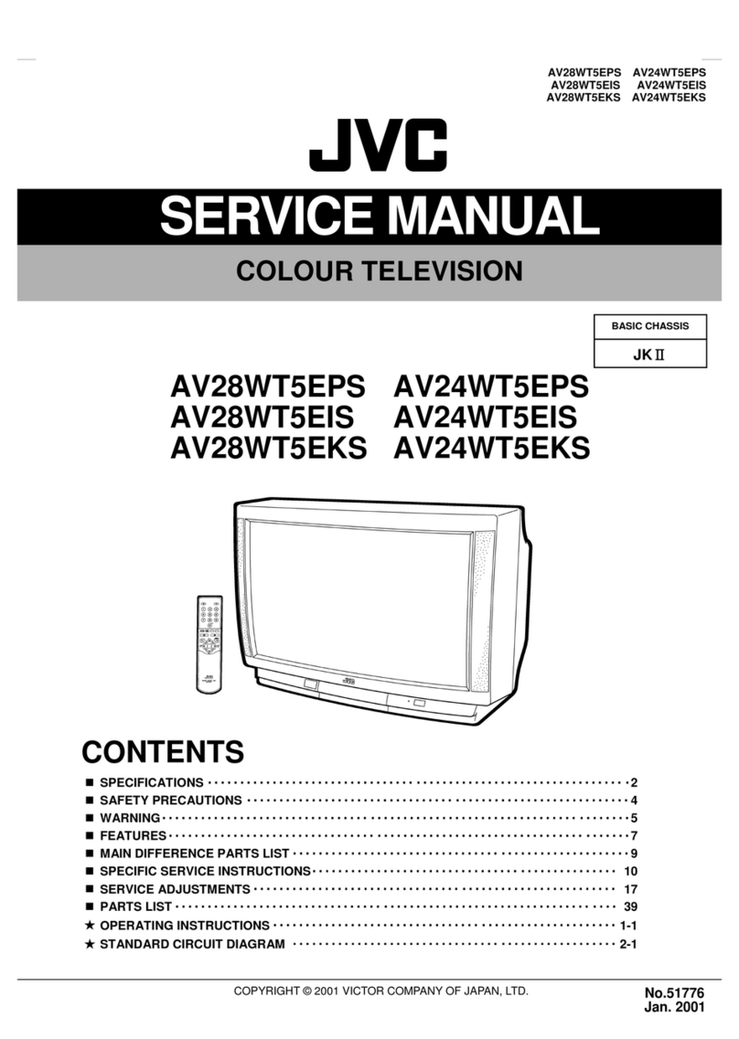
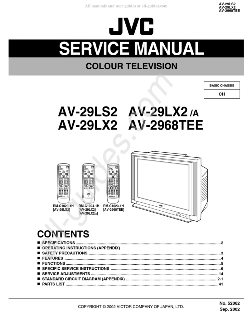
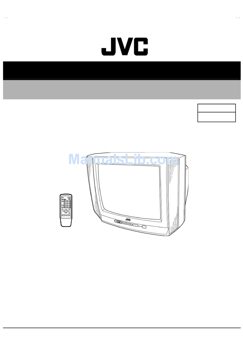
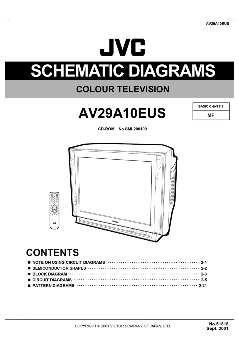
JVC AV-21E3 User manual

No. 52028
Jul. 2002
AV-21E
3
1COPYRIGHT © 2002 VICTOR COMPANY OF JAPAN, LTD.
AV-21E3
CONTENTS
!SPECIFICATIONS ・・・・・・・・・・・・・・・・・・・・・・・・・・・・・・・・
・・・・・・・・・・・・・・・・・・・・・・・・・・・・・・・・・・・・・・・・・・・・・・・・・・・・・・・・・・・・・・・・
・・・・・・・・・・・・・・・・・・・・・・・・・・・・・・・・・・・・・・・・・・・・・・・・・・・・・・・・・・・・・
・・・・・・・・・・・・・・・・・・・・・・・・・・・・・・・・・・・・・・・・・・・・・・・・・・・・・・・・・・
・・・・・・・・・・・・・・・・・・・・・・・・・・・・・ 2
!SAFETY PRECAUT IONS ・・・・・・・・・・・・・・・・・・・・・・・・・・・・・・・・
・・・・・・・・・・・・・・・・・・・・・・・・・・・・・・・・・・・・・・・・・・・・・・・・・・・・・・・・・・・・・・・・
・・・・・・・・・・・・・・・・・・・・・・・・・・・・・・・・・・・・・・・・・・・・・・・・・・・・・・・
・・・・・・・・・・・・・・・・・・・・・・・・・・・・・・・・・・・・・・・・・・・・・・
・・・・・・・・・・・・・・・・・・・・・・・ 3
!FEATURES・・・・・・・・・・・・・・・・・・・・・・・・・・・・・・・・
・・・・・・・・・・・・・・・・・・・・・・・・・・・・・・・・・・・・・・・・・・・・・・・・・・・・・・・・・・・・・・・・
・・・・・・・・・・・・・・・・・・・・・・・・・・・・・・・・・・・・・・・・・・・・・・・・・・・・・・・・・・・・・・・・
・・・・・・・・・・・・・・・・・・・・・・・・・・・・・・・・・・・・・・・・・・・・・・・・・・・・・・・・・・・・・・・・
・・・・・・・・・・・・・・・・・・・・・・・・・・・・・・・・・・・
・・・・・・
・・・ 4
!FUNCTIONS ・・・・・・・・・・・・・・・・・・・・・・・・・・・・・・・・
・・・・・・・・・・・・・・・・・・・・・・・・・・・・・・・・・・・・・・・・・・・・・・・・・・・・・・・・・・・・・・・・
・・・・・・・・・・・・・・・・・・・・・・・・・・・・・・・・・・・・・・・・・・・・・・・・・・・・・・・・・・・・・・・・
・・・・・・・・・・・・・・・・・・・・・・・・・・・・・・・・・・・・・・・・・・・・・・・・・・・・・・・・・・・・・・・・
・・・・・・・・・・・・・・・・・・・・・・・・・・・・・・・・・・
・・・・
・・ 5
!SPECIFIC SERVICE INSTRUCTIONS ・・・・・・・・・・・・・・・・・・・・・・・・・・・・・・・・
・・・・・・・・・・・・・・・・・・・・・・・・・・・・・・・・・・・・・・・・・・・・・・・・・・・・・・・・・・・・・・・・
・・・・・・・・・・・・・・・・・・・・・・・・・・・・・・・・・・・・・・・・・・・・・
・・・・・・・・・・・・・・・・・・・・・・・・・・
・・・・・・・・・・・・・ 6
!SERVICE ADJUSTMENTS ・・・・・・・・・・・・・・・・・・・・・・・・・・・・・・・・
・・・・・・・・・・・・・・・・・・・・・・・・・・・・・・・・・・・・・・・・・・・・・・・・・・・・・・・・・・・・・・・・
・・・・・・・・・・・・・・・・・・・・・・・・・・・・・・・・・・・・・・・・・・・・・・・・・・・・・
・・・・・・・・・・・・・・・・・・・・・・・・・・・・・・・・・・・・・・・・・・
・・・・・・・・・・・・・・・・・・・・・ 13
!PARTS LIST ・・・・・・・・・・・・・・・・・・・・・・・・・・・・・・・・
・・・・・・・・・・・・・・・・・・・・・・・・・・・・・・・・・・・・・・・・・・・・・・・・・・・・・・・・・・・・・・・・
・・・・・・・・・・・・・・・・・・・・・・・・・・・・・・・・・・・・・・・・・・・・・・・・・・・・・・・・・・・・・・・・
・・・・・・・・・・・・・・・・・・・・・・・・・・・・・・・・・・・・・・・・・・・・・・・・・・・・・・・・・・・・・・・・
・・・・・・・・・・・・・・・・・・・・・・・・・・・・・・・・・
・・
・31
★
OPERATING INSTRUCTIONS
★
STANDARD CIRCUIT DIAGRAM ・・・・・・・・・・・・・・・・・・・・・・・・・・・・・・・・
・・・・・・・・・・・・・・・・・・・・・・・・・・・・・・・・・・・・・・・・・・・・・・・・・・・・・・・・・・・・・・・・
・・・・・・・・・・・・・・・・・・・・・・・・・・・・・・・・・・・・・・・・・・・・・・・・
・・・・・・・・・・・・・・・・・・・・・・・・・・・・・・・・
・・・・・・・・・・・・・・・・2-1
SERVICE MANUAL
COLOUR TELEVISION
BASIC CHASSIS
CG

No. 52028
A
V-21E3
2
SPECIFICATIONS
CONTENT
ITEM
Dimensions(W×H×D) 497mm×454mm×478.5mm
Mass 21kg
TV RF System B/G, I, D/K,
RF Mode PAL / SECAM
Colour System
VIDEO Mode PAL / SECAM / NTSC3.58 / NTSC4.43
Picture Tube Visible size: 51cm measured diagonally
High Voltage 26.5kV±1.5kV(at zero beam current)
Receiving Frequency VHF (VL) 46.25MHz~168.25MHz
VHF (VH) 175.25MHz~463.25MHz
UHF 471.25MHz~863.25MHz
CATV Cable TVs of Mid (X-Z, S1-S10)
Super (S11-S20) & Hy per (S21-S41) bands receiv able
VIF Carrier 38.0MHz
Intermediate
Frequency SIF Carrier
32.5MHz(5.5MHz)
31.5MHz (6.5MHz)
32.0MHz (6.0MHz)
Colour Sub Carrier Frequency
PAL (4.43MHz),
SECAM (4.40625MHz / 4.25MHz)
NTSC (3.58MHz / 4.43MHz)
Power Input Rated Voltage AC110~240V, 50 / 60Hz
Power Consumption 90W (Max) / 60W(Avg)
Speaker 5cm×9cm, Ov al type×1
Audio Output 3W (monaural)
Aerial Input Terminal 75ΩUnbalanced
Input Video 1V(p-p), 75Ω(Front / Rear)
Audio 500mV(rms) (-4dBs), High impedance,
RCA×2 (Front / Rear)
Output Video 1V(p-p), 75Ω
Audio 500mV(rms) (-4dBs), Low impedance,
Headphone jack 3.5mm mini jack
Remote Control Unit RM-C364GY
(Battery size : AA / R06 / UM-3×2)
Design and specifications are subject to change without notice.

No.52028
A
V-21E3
3
SAFETY PRECAUTIONS
1. The d esi gn of th is pr od uct con ta in s sp eci al har d wa re , ma ny
circuits and components specially for safety purposes. For
con tinu ed pr ot ection , n o chan g es sh ou ld b e ma de to the o ri g inal
d esign un less a uth or ized i n w ri tin g by th e ma nu fact ur er .
Rep lacem en t p ar ts must b e id ent ic al to thos e u sed in th e or igin al
circu it s. S er vi ce sho ul d b e p er for med by qu alif ied p ers on nel
on ly.
2. Al te r ation s of t he desi g n or cir cuitr y of t he pr od ucts sh oul d not be
made. Any design alterations or additions will void the
m anu fact ur er's w arr a nt y and will f ur th er relieve t he ma nu factu r er
of r esp onsi b il ity for per so na l injur y or p r op erty d amag e r esul t in g
th er efr om .
3. M an y e l ectr ical an d mech anica l p arts in th e prod ucts ha ve
special saf ety-relat ed characteristics. T hese characteristics are
oft en no t e vi den t f r om visua l insp ecti on n or ca n t he pr o tect io n
aff or de d by th em nece ssar il y b e ob tai n ed b y u sin g rep l acem en t
com po ne nts ra ted f or hig he r vo l tag e, watt ag e, etc. R ep lacem en t
p arts wh ic h ha ve th ese sp eci al s afet y ch ar act er ist ics ar e
identified in the parts list of Servic e manual. El ec tric al
components having su ch features are identified by shading
on the sche matic s and by (!
!!
!) on the parts list in Service
manual. The us e of a sub sti tu te r ep la cem en t w hich do es n ot
h ave th e sam e saf ety ch ar act er ist ics as t he r eco mm en de d
r eplac em ent par t sh own i n th e p ar ts l ist of S er vice m an ual m ay
cause shock, fire, or other hazards .
4. Do n't shor t between the LIVE side ground and ISOL ATE D
(NEUTRAL) side ground or EARTH side ground when
repairing.
Some model's power circuit is partly different in the GND. The
diff er enc e of th e G ND is sho wn b y th e LIV E : ( ") side GND, the
ISO LATE D( NEUTR AL) : ( #) side G ND and EARTH : ($) side
GN D. D o n't sh or t b et we en th e LIV E si d e GN D an d
ISO LATE D(NEUTRAL) side GND or EARTH sid e GND and
n ever m ea sur e wit h a m ea sur ing a ppa r atus ( oscil lo scop e etc.)
th e LI VE si d e GND an d IS OLA TED(NE UTRAL ) sid e G ND or
EARTH side GND at the s ame time.
If above note will not be kept, a fuse or any parts will be broken.
5. If any repair has been made to the chassis, it is recommended
th at t he B1 set ting shou l d b e ch ecke d or adj u ste d ( Se e
ADJUSTMENT OF B 1 POW E R SUPPL Y) .
6. The hi gh vol ta ge app lie d t o th e pi ctu r e tu be mu st con for m wit h
th at sp ecifi ed i n S er vice m an ual. E xcessi ve h i gh vo lt ag e ca n
cau se an i ncre ase in X- Ray em issi on , ar cing an d possib le
component damage, therefore operation under excessive high
voltage conditions should be kept to a minimum, or should be
preve nt ed. If s evere arc in g occur s, r emove t he AC power
immed i ate ly an d de ter m ine th e ca use b y visua l i nsp ect io n
( in cor r ect in stal lat ion, cr acke d or m elte d hi gh vo lt age har n ess,
p oor so ld eri ng, et c.). T o m aint ain the p r ope r min im u m l e vel of
sof t X-Ray em ission, c omp on en ts i n th e hi gh voltag e cir cui tr y
includ ing t he pi ct ur e tu be must b e t he e xact r ep lacem e nts or
alte rn at i ves ap pr ove d b y th e ma nuf act ur er of th e c om plet e
pr od uct.
7. Do n ot c hec k high volt ag e b y drawing an arc. Use a high volt ag e
m eter or a hig h v ol tag e pr ob e wit h a V T VM. D ischa rg e th e
picture tube before attempting meter connection, by connecting
a clip le ad to th e gr ou nd f ra me a nd c onn ecti n g th e oth er end of
the lead through a 10kΩ2W resisto r to the an od e b utt on .
8. W hen se r vi ce is requ ir e d, ob ser ve th e or igina l lea d dr ess. E xtr a
pr ec aut i on sh ou ld b e g i ve n t o assur e cor r ect l ea d dr ess i n th e
hig h voltag e ci rcui t a r ea. W her e a s hort ci rcui t h as occu rr e d,
th ose co mp on ent s tha t indica te evi de nce of ove r hea ting sho ul d
b e r e place d. A lwa ys u se th e ma nuf act ur er's r ep lacem en t
components.
9. Isolation Check
(Safety for Electrical Shock Hazard)
Af ter r e-ass emb lin g th e p r odu ct, alw ays perf orm an i solat io n
ch eck on the expo sed me tal p ar ts of t he cabi n et ( a nte nn a
ter m ina ls, vid eo /au di o i npu t and ou tpu t t er mi n als, Con tr ol kn obs,
m etal cabi n et, scr ewhe ad s, ea r ph one j ack, con tr ol shaf ts, etc.)
to be su re th e p r odu ct is s af e t o o pe r ate with ou t d an ger of
elect rical shoc k.
(1) Dielectric Strength Test
The i so lation be tw een the A C pr im a ry ci rcu i t an d al l me tal p ar ts
exp ose d t o th e us er , p ar ticular ly an y e xp os ed met al p art h avi ng a
r etu rn p ath to t he chass is sho ul d wi ths tan d a volt age of 3 000 V
AC (r.m.s.) for a period of one second.
( . . . . W it hstan d a vo lt ag e of 1 10 0V A C (r .m. s.) t o an ap plianc e
r ate d up to 12 0V , an d 3 00 0V AC ( r .m. s.) to an ap pl ian ce r at ed
200V or more, for a periodof one second.)
This method of test requires a t est equipment not generally found
in t he ser vic e trad e.
(2) Leakage Current Check
Pl ug th e A C lin e c ord d ir ect l y in to th e A C ou tlet ( d o n ot use a lin e
isolati o n tr ansf or mer du r in g this ch eck.). U si n g a " Lea kag e
Cur rent Teste r", me asur e th e l ea kag e cu rre nt f rom each exp osed
m etal p ar t of the ca bi ne t, p art icu l arl y any e xpos ed me tal p ar t
h aving a re turn pa th to t he ch assis , t o a kn own go od ea rt h
gr ou nd (wa ter pip e, e tc.). An y l eaka ge cur ren t m ust n ot e xceed
0.5mA AC (r.m.s.).
Howeve r, i n tr op ic al ar ea , th is mu st no t exce ed 0.2 mA AC
(r.m.s.).
"
""
"Alte rnat e Ch e ck Met hod
Pl ug th e A C lin e c ord d ir ect l y in to th e A C ou tlet ( d o n ot use a lin e
isolati o n tr an sfor mer dur ing t hi s che ck.). U se an AC vo lt me ter
h aving 1 00 0 oh ms pe r vol t or m or e sens it i vi ty in th e fo llowi ng
m ann er. C on nec t a 1 50 0Ω10W res ist or par a lle le d b y a 0 .1 5µF
AC -type c apa cit or bet we en an expo sed met al pa rt a nd a kno wn
g ood e ar th gr o un d ( wa ter pi pe , etc.) . M eas ur e th e A C vo lt ag e
acr oss th e r es ist or with th e AC vo l tm eter . M ove th e r esi stor
con nec tion to e ach exp ose d me tal par t, p art icular ly a ny exp osed
m etal p ar t havin g a r etu rn pat h to t he ch assis, an d m easu r e th e
AC vol tag e ac ro ss the r es ist or . N o w, re verse th e plu g i n th e AC
ou tl et and re pe at eac h m ea sur emen t. An y vol t ag e me asu re d
must not exc eed 0.75V AC (r.m. s.). This c orresponds to 0.5mA
AC (r.m.s.).
Howeve r, in tropica l area, this must not exceed 0 .3V AC ( r.m. s.).
This corresponds to 0.2mA AC (r.m.s.).
0.15μF A C-T YPE
1500 Ω10W
GOODEARTH GROUND
PLACE THIS PROBE
ON E A CH EX PO SE D
ME T AL PA R T
ACVOLTMETER
(HAVING 1000 Ω/V,
OR MOR E SENSIT IVITY)

No. 52028
A
V-21E3
4
FEATURES
"New ch assi s d esi gn en ables us e of an i nt er acti ve on-scr ee n c ont ro l.
"W ide r an ge volt age ( 1 10V ~240V) AC power input.
"With AUDIO / VI DE O INPUT & OUTPUT terminal.
"MUTING but ton can red uce th e a udio level to zer o inst ant ly.
"Funct i on al r em ote co ntrol t o o per a te T V set (f or ch ann el se l ect, vol ume c on tr ol, p ow er ON/OF F, etc. ) f r om a d ist anc e.
"I
2C bu s con trol ut ilizes single chip ICs for IF, V /C, DEF. V SM PRES ET, PRESET & S ETU P TOU R.
"By m e ans of AUT O PR OGR A M, th e T V s tatio ns c an b e s electe d aut om ati ca lly a nd th e TV cha nn els can al so b e r earr an ge d a ut om ati cally.
"Built- in E CO MO DE ( ECONOM Y, ECOLOG Y)
In acco rd anc e with th e br ig ht ness i n a r oo m, th e br ig ht ness and / of con tr ast of th e p ictur e can b e a dj ust ed au tom at ic al ly to m ake th e
op ti mu m pictu re whi ch is eas y on th e e ye.
"Built – in ON TIMER, RETURN + & CHILD LOCK.
SYSTEM BLOCK DIAGRAM
"
IC301
VIDEO/CHROMA
DECORDER
IC702
MEMORY
TU001
TUNER
IC701
MICRO
COMPUTER
SCL 1/SDA1
SCL 2/SDA2

No. 52028
A
V-21E3
5
FUNCTIONS
■
FRONT PANEL
■
REAR TERMINAL
■
■
REMOTE CO NT RO L UNIT ECO SENSOR key
SOUND SYSTEM key
COLO UR SY STEM ke y
TV/VIDEO key
OFF TIMER key
CHA NNE L SC AN k ey
RETURN+key
DISPLAY key
CHANNEL key
POWER key
PICTURE MODE key
Number (CH.) key
-/-- key
MUTING key
MENU key
MENU ▲/▼key
MENU -/+key
VOL UME-/+key
1
2
3
4
5
6
7
8
9
10
11
12
13
14
15
16
1
2
3
4
5
6
7
8
9
10
11
12
13
14
15
16
MENU buttons
CHANNEL -/+buttons
VOLUME -/+bu tto ns
AI ECO sensor
RE MO TE CONTROL s ens or
ON TIMER lamp
POW E R la mp
MAINPOWERbutton
A/V INPUT t erminal
HE ADPHONE jack
1
2
3
4
5
6
7
8
9
10
10 9 1 2 3 4 5 6 7 8
ANT Terminal
VIDEO INPUT Terminal
AUDIO INPUT T erminal
AUDIO OUTPUT Terminal
VIDEO OUTPUT Terminal
1
2
3
4
5
2
3
4
5
1

No. 52028
A
V-21E3
6
SPECIFIC SERVICE INSTRUCTIONS
DISASSEMBLY PROCEDURE
REMOVING THE REAR COVER
1. Unp lu g t he po we r plu g.
2. As sh own i n f i gure , r emove t he 5screws marked !
!!
!an d a
screw marked "
""
"and a screw mar ked #
##
#.
3. Rem ove th e b ack bo ar d an d r e mo ve the p ow er c ord f ro m th e
rear c over.
4. W ithdr a w t he r ear co ver to wa rd you .
REMOVING THE MAIN PW BOARD
"After removing the rear cover.
1. Sl ight ly r aise t he bo th si de s of th e M AIN PW Boa rd b y h an d and
r emove the PW B stop per of M AIN P W Bo ard .
2. W ithdr a w t he M AIN PW Boa rd b ackw ard.
( If n ecess ar y, ta ke off the wir e clam p, c onn ect or s etc. )
REMOVING THE SPEAKER
"After removing the rear cover.
1. As sh ow n i n figu r e, r emove th e 2screws marked $
$$
$.
CHECKIN G THE MAIN PW BOARD
1. To ch eck the ba ck si de of th e PW B oar d.
1) Pu ll out the MA IN PW Bo ar d. ( Ref er to RE MO VING T HE M AIN
PW B oard)
2) Er ect th e PW Boar d ve rt ic al ly so th at you ca n easily ch eck th e
b ack side of th e PW B oar d.
[CAUTION]
"W hen e re cting th e PW Boar d, be car ef ul s o t hat th ere wil l b e n o
contacting with other PW Board.
"Before turning on power, make sure that the CRT earth wire and
oth er co nne cto r ar e p r ope rly c onn ect ed.
WIRE CLAMPING AND CABLE T YING
1. Be sure t o clamp the wire.
2. Never r em o ve th e c abl e ti e use d f or tyi ng th e w ire s to ge the r.
Sh oul d i t be i nad verte ntly r emove d, b e su re to tie th e wir es w it h a
new cable tie.

No. 52028
A
V-21E3
7
CRT SOCKET
PWB
FRONT CABI.
POWER
CORD
(×
××
×2)
(×
××
×5)
SP EAKE R
D
C
B
A
MAIN PWB
REAR
COVER
PW B STOPE R
HV T
BACK BOARD
(×
××
×1)
(×
××
×1)

No. 52028
A
V-21E3
8
REPLACEMENT OF MEMORY ICs
1. MEMORY ICs
Thi s m od el u ses me mo r y I Cs. T his me mo ry IC da ta are f or pr o per opera tion of th e vi de o a nd d eflect io n ci rcuits.
W hen rep la ci ng me m ory ICs, b e su r e to us e ICs w rit ten wi th t he initi al va lu es of dat a.
2. PROCEDURE FOR REPLACIN G MEMORY IC s
(1) Power off
Sw itch the p ow er of f an d di sco nn ect t he pow e r plu g f rom t he w all out l et.
(2) Replace ICs
Be sure to use memory ICs written with the initial data values.
(3) Power on
Con nect th e p ow er pl u g i nt o t he w all ou tlet and sw itch t he po we r on .
(4) Check and s et SY STEM CONSTANT SET
・
・・
・It must not adjust without adjustment signals.
1) Press t he DI SPLAY ke y and th e PICTURE MODE key of the REMOTE
CONTROL UNIT simultaneously.
2) The SERVICE MENU screen of Fig. 1 will be displayed.
3) W hil e th e SE RV ICE M EN U i s di spl ayed , ag ai n press the DI SPLAY key and
PICTURE MODE ke y sim ulta neo usl y, an d t he S YSTEM CON STA NT SE T
scr een of Fig. 2 w ill b e di spla ye d.
4) Check th e sett in g valu es of th e SYS TEM C ONSTA NT SET of T able 1 If th e
value is diff erent, select the s etting item with th e MENU ▼/▲key, and s et
th e co rrect val u e w ith t he MENU - / + k ey.
5) Press the DI SPLAY ke y twi ce, and r etu rn t o th e n or mal scr ee n.
(5) Receive channel of setting
Refer to th e OPE RATI NG I NST RUCTIONS an d set th e r ece ive cha nn el s
( chan ne ls pr ese t) as descr ibe d
(6) User Setting
Check t he us er s etti n g valu e of Tab le 2, a nd if se tti ng val ue is dif fer en t, set
th e co rrect val u e.
For setting, refer to the OPE RATI NG INSTRUCTIO NS .
(7) Setting of SERVICE MENU
Ve rif y the set ting it ems of th e SE RVIC E M ENU , and r eset w he re n ecessa r y.
For setting, refer to the SERVICE ADJUSTMENTS.
S
ERVI
C
E MEN
U
1.IF 2.V
/C
3.DEF 4.VSMPRESET
5.PRESET
6.SETUP TOUR OFF
1-6 SELECT DISP : EXIT
******
************
****** *****
**********
***** **
* ** *
* *
.
****
********
****
*** ** **
*** ** ***** ** **
*** ** ** ** ***
** ***** ***
** ***
Fig.1
Fig.2
SY STEM C ONSTANT- Ⅰ
ⅠⅠ
Ⅰ
CO
L
OU
R : TRIPLE
BI LIN G UAL : N O
TUNE R : MU
ECO SENSOR : YES
L ANGU AGE : E / R
SYSTEM CONSTANT SE T 1
: SELECT
- / + : OPER ATE DISP : EX IT
/
SY STEM C ONSTANT- Ⅱ
ⅡⅡ
Ⅱ
B/B SOUND : OFF
LOCK : 180
COL OUR AU T O : NO
QSS : MINT
ALC : NO
TEXT RATE : 2 0
SYSTEM CONSTANT SE T 2
:
S
EL -
/
+ :
O
PE DI
S
P : E XIT/
SY STEM C ONSTANT- Ⅲ
ⅢⅢ
Ⅲ
AMP T
U
NER : N
O
VNR : YES
TEXTTABLE : CYL
VOLUM PWM : POS
SYSTEM CONSTANT SE T 3
: SEL - / + :OPEDISP : E XIT/
KEY ASSIGNMENT OF REMOTE CONTROL UNIT
MENU
▼/▲key
MENU
-/+key
DISPLAY
key
PICT URE
MO D E ke y
NUMBERS
key

No. 52028
A
V-21E3
9
SE TTING OF SY STEM CON STA NT SET
Setting item Setting contents Setting value
COLOUR TRIPLE
BILINGUAL NO
TUNER MU
AI ECO S ENSOR YE S
LA NG UA GE E / R
B/B SOUND OFF
LO CK YES 10 20 ~230 240 250 18 0
COLOUR AUTO NO
QSS MI NT
ALC NO
TEXT RA TE 10 20 40 80 20
AMP TUNER NO
VNR YE S
TEXT TABLE CYL
VOL UM PW M POS
Table 1
US ER SE TTING V ALU ES
Setting item Setting value Setting item Setting value
SUB POWER ON LANGUAGE ENGLISH
CHA NNE L PO SITIO N 1 PO SITIO N CHA NNE L P RE SET Refe r t o OPE RATING I NS TRUCTION
VOL UME About 10 AI ECO S ENSOR OFF
TV/VIDEO TV VNR OFF
ON SCREEN DI SPL AY POS ITION INDICATIO N AUTO S HUTOFF OFF
COLOUR SYSTEM PAL ON TIMER PR1 0:00
SOUND SYSTEM B / G BLUE BACK OFF
OFF TIMER OFF OSD.Shows 00 CHILD LOCK OFF
PICTURE MODE (VSM) BRIGHT SETUP TOUR ON
Table 2
YE S NO
YE S NO
ON OFF
YE S NO
MI NT MQ SS
YE S NO
YE S NO
YE S NO
ARA CYL
MU MA
MUL T I. PA LTRIPLE
POS NEG
E/R/A /P E
/
R

No. 52028
A
V-21E3
10
INITIAL SETTING VALUE OF SERVICE MENU
1. Ad justment of t he SE RVICE MENU is m ade on t he bas is of the initial s etting values ; howev er, t he new se tting va lues w hi ch
set the screen in its optimum condition may differ from the initial setting.
2. Do not change the initial Setting Values of the Setting (Adjustment) items not listed In “ADJUSTMENT”.
2. V/C
Initial se tting v al ue
Colour s
y
stem
Setting item
Va riabl e
range PA L SE C AM NT SC 3. 5 8 NT SC 4.4 3
RED
GREEN1. CUT OFF
BL UE
- 128 ~+127 -50
RED
2. DRI VE BL UE - 128 ~+127 + 0
3. BR I G HT -127~+127 + 0
4. CONT . -63~+6 3 + 0
5. COLOUR -63~+6 3 + 0
TV + 0 + 0
6. TINT VI DE O
-63~+6 3 + 0 + 0
7. SECAM BL ADJ. -31~+3 1 + 0
TV -8(Fixed)
8. SHARP (Do Not Adj.)
VI DE O
-32~+3 1
+15(Fixed)
3. DE FLECTION
Initial se tting v al ue
Setting item Variable range
fv : 50Hz MODE fv : 60Hz MODE
1. VER. POS ITION -04 ~+03 - 1 - 3
2. HOR. POSITION -16 ~+15 + 3 + 3
3. VER. HE IGHT -64 ~+63 -35 + 1
4. VER . L I NE AR I TY -32 ~+31 +15 - 1
5. VER. S CURV E -32 ~+31 -32 + 0
6. H O R. VC O AD J UST (Do Not Adj.) -63 ~+62 + 0 + 0
4.VS M PRESE T
VS M
p
r ese t
mode
VS M
Setting item
BRIGHT STANDARD SOFT
TINT SE TTING VA LUE +1 5
COLOUR SE TTING VA LUE +15
BR IG HT SE TTING VA LUE +1 5
CONT. SE TTING VA LUE +30 +15 +11
SHARP SE TTING VA LUE +1 5 +1 2

No. 52028
A
V-21E3
11
5. PRESE T
The items in the following table, it is no requirement for adjustment.
If values had changed by the mi ss operati on, set the initial setting values i n the fol lowing table .
Colou r Sy st em Do Not Adju st
Initial setting value (Fixed value)
Setting item
PA L SE C AM NT SC 3. 5 8 NT SC 4. 4 3
1. C TRAP FIX 1 1 1 1
2. SHARP PEAK 0 0 0 0
3. ABL 1 1 1 1
4. GAMMA 0 0 0 0
TV 0 2 2 3
5. Y. DELAY TIME
VI DE O 0 2 0 2
6. BL ACK EX P START +3+3+3+3
TV 1 1 0 0
7. C-BPF
VI DE O 1 1 1 1
8. CW / SCP 0 0 0 0
9. VIF DET LEVEL 0 0 0 0
11. IF AGC MIN 0 0 0 0
12 . VIF AGC 0 0 0 0
13. VIF PMOD 0 0 0 0
19 . VNR 15 15 15 15
20 . R GB L IM 1 1 1 1
21. RGB LIMIT LEVEL 2 2 2 2
23. TEXT H. POSITION -3 -3 -3 -3
24. READ DATA
Sound System D o No t Ad ju s t
Setting item B/G I D/K M
10. SIF DET LEVEL +0+0+0+0
14. SIF BPF BW ADJUST +0+0+0+0
15. SIF TRAP FO ADJUST +0+0+0+0
16. SIF TRAP FO ADJUST 2 +0+0+0+0
17. SIF -TRAP 0 0 0 0
18. SIF -BPF 1 0 0 0
22 . SIF S W 0 1 1 1

No. 52028
A
V-21E3
12
REPLACEMENT OF IC301 (IF V/C DECODER)
"For the I C301(IF V /C DECODER) of this model, a ll data are written in the micr o-c ompute r. So, wri te the data i n the micro-
computer in accordance with the following procedures before starting adjustment.
PROCEDURES
(1) Turn t he POW ER O FF.
(2) R ep lace t he IC30 1 w ith a n ew o ne .
(3) W hi le pr essing ME NU bu tto n a nd VO L+ bu tto n ON the F RO NT CABINE T s im ult ane ous l y, t ur n th e POW ER O N. W h en th e POW ER is
turned ON, th e dat a is wr it ten in t he micro-co mp ute r im med iately.
LOCATIONS OF FRONT PANEL BUTTONS AND LAM PS
MENUbuttons
CHANNEL ・/ ・buttons
(ME NU ・/ ・bu tt ons)
VOLUME
-/+buttons
(MENU -/+bu tto ns)
AI ECOsensor
REMOTE CONTROL sensor
ON TIMER lamp
POWERlamp
MAIN POW ER button
MENUbuttons
CHANNEL -/+buttons
(ME NU -/+buttons)
VOLUME
-/+buttons
(MENU -/+bu tto ns)
AI ECOsensor
REMOTE CONTROL sensor
ON TIMER lamp
POWERlamp
MAIN POW ER button
1
2
3
4
5
6
7
8
12345678

No. 52028
A
V-21E3
13
SERVICE ADJUSTMENTS
BEFORE STARTING SERVICE ADJUSTMENT
1. There ar e 2 w ay of adjus ti ng t hi s TV: One i s wi th the
REMOTE CONTROL UNIT and the other is the conventional
method using adjustment parts and components.
2. The adjustment with the REMOTE CONTROL UNIT is made
on the basis of the initial setting values. The setting values
which adjust the screen to its optimum condition may differ
from the initia l s etti ng v al ues.
3. Make s ur e that connect ion is c orrect ly ma de t o AC p ower
sourc e.
4. Tur n on t he p ow er of th e se t an d eq ui pmen t bef or e us e, an d
sta rt t he ad ju stmen t pr oc edur e s af ter w aitin g at l east 30 min ute s.
5. Unless ot her wi se spec if ied, p r ep ar e th e mo st sui ta bl e r ec eptio n
or i np ut si gn al for adjust ment.
6. Nev er t ouc h a ny adju s tme n t parts, whi ch ar e not spe cif ied
in t he li st f or thi s ad just me nt VRs , t ra nsf or ms, c ond e nser s,
etc.
7. Pr ep arati o n f or ad justm en t
Unless otherwis e specified in the adjustment instructions, preset
the following functions with the REMOTE CONTROL UNIT.
User mode position
PICTURE MODE (VSM) BRIGHT
VNR OFF
TINT / COLOUR / BRIG HT
CONT. / SHARP CENTER
BL UE BA CK OFF
OFF TIMER OFF
AI ECO S ENSOR OFF
AUTO SHUT OFF OFF
MEASURING INSTRUMENT AND FIXTURES
1.DC voltmeter (or digital voltmeter)
2.Oscilloscope
3. Sign al g en erat or (P att er n g en er at or) [ PAL / S ECAM / N TS C]
4.Remote control unit
ADJUSTMENT ITEMS
Ad justment item Ad justment item
B1 POW E R SUPPL Y DEFLECTION circuit adjustment
FOCUS adjustment VSM PRESET s etting
IF circ uit a djust ment PURITY/ CO NV ERGENCE adjus tment
V/C (Video / Chroma) circuit adjustment

No. 52028
A
V-21E3
14
BASIC OPERATION OF SERVICE MENU
"The adjustment using SERVICE MENU
The f ollowing adjus tme nt it ems u se t he SE RV ICE MENU in th e ser ies of the adju stm ent . The ad ju stment s ar e m ade on the bas is of the
initi al se tti ng valu es. T h e ad ju stm ent val u es w hich ad ju st t he scr een to th e o ptim um co ndi t io n c an b e di ffe re nt from th e in itia l sett in g va l ues.
W ith th e S ER VIC E ME NU, var ious s ett in gs c an be m ade , a nd the y ar e broa dl y cl assifi e d i n th e f ollo wi n g i te ms of s ettin gs.
1.I F ・・・・・・・ ・・・・・・・・・・・・・ ・・・ Adju stment of the IF circuits.
2.V /C ・・・・・・・ ・・・・・・・・・・・・・ ・・ Ad ju stm en t of th e VID EO /CHRO MA ci rcui t.
3.DEF ・・・・・・・ ・・・・・・・・・・・・・ ・ Adjustment of the DEFLECTION circ uit.
4.V SM PRES ET ・・・・・・・ ・・・・・ Ad ju stm en t of th e init ia l sett in g va l ue s of VSM co nd it i on as ST A NDA RD, SOFT a nd BR IGHT.
(VSM : Video Status Memory)
5.PRESET ・・・・・・・ ・・・・・・・・・・ Adjustment of the RF circ uit [Do not adjust].
6. SETUP TOUR OFF ・・・・・・・ It s hou ld b e able to select m ode (LANGUAG E a nd AUTO CH PRESE T)..
[Shou ld be O FF].
"Key operation of the SERVICE MENU
[Enter to SERVICE MENU]
Press the DI SPLAY key and the PICTURE MODE key of the REMOTE CONTROL
UNI T simu lt an eou sl y. T h en ent er th e S ERVIC E ME NU m od e as sh own in Fi g.1 .
[Exit from SERVICE MENU]
W hen co m plete th e ad just me nt w ork, pr ess th e DI SPLAY key to return t o the
SERVICE MENU.
An d th en press th e DI SPLAY ke y ag ai n, r etur n to th e n or mal screen .
[ Se lec t fr om SE R VIC E M E NU ]
In SERVI CE MENU, press t he n umber (1 ~6) ke y of th e r em o te c ont ro l un it , to se l ect
an y of th e ad justm en t i te ms.
The col o urs w hich se le cte d i te m ch ar act ers a r e ch ang ed .
SE RV ICE M ENU
SE RV ICE ME NU
1.IF 2.V/C
3
.DEF 4.V
S
M PRE
S
ET
5.PRESET
6.SETUP TOUR OFF
1-6 SELECT DISP :EXIT
******
************
***********
**********
***** **
****
**
.
***
******
***
*** ** **
*** ** ***** ** **
*** ** **** ***
** ***** ***
** ***
Fig.1
KEY ASSIGNMENT OF REMOTE CONTROL UNIT
MENU
▼/▲key
MENU
-/+key
DI SP LA Y k e y
PICT URE
MO D E ke y
NUMBERS
key

No. 52028
A
V-21E3
15
[Method of setting]
1. IF
[1. VCO]
①1 K ey ・・・・・・・ ・・・・・・・・・・・・・ ・・・・・ Select 1.IF.
②1 K ey ・・・・・・・ ・・・・・・・・・・・・・ ・・・・・ Select 1.VCO
③The VCO (CW) screen will be displayed a allow mark when the AFC voltage is at a certain level.
④DISP LA Y K ey・・・・・・・ ・・・・・・・・・・・ As you press this key twice, you will return to the SE RVICE M E NU .
[2. DELA Y P OINT]
①1 K ey・・・・・・・ ・・・・・・・・・・・・・ ・・・・・ Select 1.IF.
②2 K ey・・・・・・・ ・・・・・・・・・・・・・ ・・・・・ Se lect 2.DELAY P OINT.
③ME NU - /+ K ey ・・・・・・・ ・・・・・・・・・・ Set (adju st) the setting valu es of the s etting ite ms.
④DISPLAYKey・・・・・・・ ・・・・・・・・・・・ W hen th is is presse d t wice, you will r et urn t o t he SE RV ICE MENU .
2.V /C, 3.DEF an d 4 .V SM PRES ET
①2~4Key ・・・・・・・ ・・・・・・・・・・・・・ ・・・ Select one from 2. V/C, 3. DE F an d 4. VSM PRE SET.
②MENU ▼/▲Key ・・・・・・・ ・・・・・・・ Select s etting items.
③MENU-/+ Key ・・・・・・・ ・・・・・・・・・・ Adj u st th e va lues of t he item s.
④DISP LA Y K ey ・・・・・・・ ・・・・・・・・・・・ W hen th is is pr esse d, r e tur n t o t he SE RVICE MEN U.
6.SE TUP TOUR
①B y p r essing the 6 key, you can ch ang e t he ON or OFF ( should be OFF).
(ShouldbeOFF)
%・If it is ON, th en you tu rn th e TV po we r off , w h en you ar e t ur n t he TV p ower o n a ga in .
The JVC’s logo will be shown about 15 seconds automatically.
②MENU -/+ Key ・・・・・・・ ・・・・・・・・・・ Select Language.
③MENU ▼Key・・・・・・・ ・・・・・・・・・・ Au to Se arch.

No. 52028
A
V-21E3
16
SERVICE MENU FLOW CHART
S
ERVI
C
E MEN
U
1.IF 2.V/C
3.DEF 4.VSMPRESET
5.PRESET
6
.
S
ET
U
P T
OU
R
O
FF
1-6 SELECT DISP : EXIT
******
************
***********
**********
***** **
* ** *
* *
.
****
********
****
*** ** **
*** ** ***** ** **
*** ** **** ***
** ***** ***
** ***
SE RV ICE M ENU
IF
1. VCO
2. DELAY POI NT
1-2 :
S
ELE
C
T DI
S
P : E XI T
SU B M E NU 1. I F
VCO (CW)
***.**
MH z
T
OO
HI
G
H
ABOVE REFERENCE
JUST REFERENCE
BELOW REFERENCE
TOO LOW
AFT AD
JUS
T
** *(* *)
** *(* *)** *(* *)
** *(* *)
VCO ADJUST
** *(* *)
** *(* *)** *(* *)
** *(* *)
FINE
DISP : EXI T
DELAYPOINT UHF
AGC T AKE- OVER
**
- / + : OPERATE DISP: EXIT
6
.
S
ET
U
P T
OU
R
O
N
/
OFF
(By pressing 6-key)
BRIGHT
TINT
COLOUR
BRIGHT
CONT.
SHARP
-
/
+ :
O
PERATE DI
S
P : EXIT
**
**
**
**
**
SUB ME NU 4. V SM PRES ET
/ :SELECT
DEF
- / + : OPERATE DISP :EXIT
**
SU B M E NU 3. D EF
/ :SELECT
50
Hz
1. VER. POSITION
PAL
V/C PAL
1. CUTOFF
- / + : OPERATE DISP :EXIT
(
R
)
* **
(G)
* **
(B)
* **
50Hz
SU B M E NU 2. V /C
/ :SELECT
PRESET
1.
C
-TRAP FI X
- / + : OPERATE DISP :EXIT
*
50
Hz
SUB ME NU 5. P RE SET
/ :SELECT
B
/
K
PAL
O
FF

No. 52028
A
V-21E3
17
ADJUSTMENT LOCATIONS
S
1Pin TP-91(B1)
2Pin NC
3Pin X-ray2
4Pin X-ray1
5Pin TP-E( )
HVT
S
1
HV
U
IC301
MEMORY IC
IC702
IC701
F901
DEG
TU00 1
FRONT
TOP
MAIN PWB
CRT SOCKET PWB
(SOLDER SIDE)
TP-47G /R
E1
U
T
PW
UPPER:FOCUS
LOWER:SCREEN
TP-47R/G
TP-47B
TP-E
T
CRT EARTH WIRE
(BRAIDED ASS'Y)
S
4

No. 52028
A
V-21E3
18
ADJUSTMENTS
B1 POWER SUPPLY
Item Measuring
instrument Test point Ad justment part Description
Check of
B1 Power
Supply
Signal
generator
DC Vo lt -
meter
TP-91 ( B1)
TP-E (#
##
#)
1. Inp ut a wh ole bl ack sig na l.
2. Connect a DC voltmeter to TP-91(B1) and TP-E (#).
3. M ake sur e t hat th e vol t ag e is D C1 16. 5±2.0 V.
FOCUS ADJUST MENT
Item Measuring
instrument Test point Ad justment part Description
Ad ju st men t
of FOCUS
Signal
generator
FOCUS VR
[In HVT]
1. Input a cross-hatch signal.
2. While watching the screen, adjust the FOCUS VR to make the
ver ti cal and ho rizo nta l l in es as f in e a nd sha rp as possi b le.
3. M ake sur e t hat w he n th e s cre en is d ar ken ed, th e lines r emain in
g ood focu s.
IF CIRCUIT ADJUSTMENT
Item Measuring
instrument Test point Ad justment part Description
●Please use signal generator which is correct proof about the
sen ding fr eq ue ncy.
Ad ju st men t
of VCO
(
CW
)
Signal
generator
Remote
control unit
1. VCO
1. Inp ut th e PA L f ul l colo ur b ar (2 10 .2 5MHz) sig nal .
2. En ter th e SERVIC E ME NU.
3. Sele ct 1 .IF f rom t he SERV ICE MENU.
4. Press 1 key and s elect 1. VCO.
5. Select VCO ADJ US T with MENU ▲/▼key.
6. Press MENU -/+ key until the colour of the characters TO O
HIGH ch an ges b lu e to ye llo w . Th en g r ad uall y pr ess th e MEN U
- /+ key u ntil th e T OO LOW ch ang es ye l low. At this t ime, conf ir m
th at t he val u e of VCO ADJUST is n ear +00 .
0. Select AFT ADJUST with MENU ▲/▼key.
8. Press MENU -/ + key until the characters JUST REFERENCE
ch ang es b l ue to yel low .
9. Press the DI SPLAY key three times to return to normal screen.
VCO (CW)
***.**
MHz
TOO HIGH
AB OVE REFEREN CE
JU ST REF ER ENCE
BELOW R EFEREN CE
TOO LOW
AF T AD JUST
** *(* *)
** *(* *)** *(* *)
** *(* *)
VCO ADJUST
** *(* *)
** *(* *)** *(* *)
** *(* *)
FINE
DISP :EXIT
YE LLOW
D
o
n
ot
adjust
ADJUST MEN T AT T HIS POINT IS USELES S
AB
O
VEREFEREN
C
E
TOO HIGH
B ELO W RE F E RE NC E
J US T R EF E RE NC E
TOO LOW
ADJUSTMENT POINT

No. 52028
A
V-21E3
19
Item Measuring
instrument Test point Ad justment part Description
Ad ju st men t
of DELAY
POI NT
(AGC)
Signal
generator
Remote
control unit
DE LAY POINT
(AGC TAKE-OVER)
1. Inp ut a bl ac k an d wh it e si gn al ( col o ur of f).
2. En ter th e SERVIC E ME NU.
3. Select 1. IF f rom t he SERVI CE M ENU.
4. Select 2. DELAY P OINT b y pressin g th e 2key on the remote
control unit.
5. Set th e set tin
g
valu es of th e set ti n
g
item s as s ho wn bell o w t abl e .
6. Then adjust the MENU - / + key until video noise disappears.
7. Tur n to oth er ch an nel s and m ake su r e th at the r e ar e n o
irregularities.
Setting It em Variabl e range Initial se tting v alue
MATSUSHITA
(Q
A
U0
2
8
7-
00
1
)
MURATA
(Q
A
U0
1
85
-
00
4
)
ALPS
(Q
A
U0
2
8
2-
00
1
)
NT SC 3.5 8
45 45 47
DE LAY POINT
(AGC TAKE OVER) OTHER
0~127
35 45 35
DELAY POINT UHF
AGC TA KE-OVER
**
- / + :OPERATE DISP : EXIT

No. 52028
A
V-21E3
20
VIDEO / CHROMA CIRCUIT ADJUSTMENT
The setting (adjustment) using the REMOTE CONTROL UNIT is made on the basis of the initial setting values.
The setting values which adjust the screen to the optimum condition can be different from the initial setting valu es.
Do not c hange the initial setting v alues of the setting items not listed in “ADJ USTMENT”.
Item Measuring
instrument Test point Ad justment part Description
Ad ju st men t
of WHITE
BALANCE
(Low light)
Signal
generator
Remote
control unit
1. CUT OFF (R)
CUT OFF (G)
CUT OFF (B)
SCREENVR
[IN HVT]
1. Inp ut a bl ac k an d wh it e si gn al ( col o ur of f).
2. En ter th e SERVIC E ME NU.
3. Select 2. V/C from the S ERVICE MENU, then selec t 1 . CUT OFF
(R), (G) and (B) .
4. Set each value to initial setting value with 4~9 keys of the
remote control unit.
5. Press the 1key of th e re mo te co ntr ol un i t to sh ow th e sin gl e
horizontal line on screen.
6. Tur n t he SCREEN VR fully counter-clockwise, then slowly turn it
clockw is e to wh ere on e of a r ed , bl u e or gr e en co lour is f ai nt ly
vis ible.
7. Use keys 4~9of th e r emote c ontr o l u ni t an d ad ju st the oth er 2
colo ur s wh ich e xcep t th e ap pea r ed col o ur to w he re th e sin gle
h orizo nt al l in e app ea rs wh it e.
8. Turn the SCREEN VR to wh ere t he si n gle h or iz ont al lin e g l ows
fain tly.
9. Press the 2key to turn off th e single horizontal line.
10. Press the DI SPLAY key t wice to return to the n ormal screen.
Ad ju st men t
of WHITE
BALANCE
(High light)
Signal
generator
Remote
control unit
2. DRI VE
(R)
DRI VE (B)
1. Inp ut a bl ac k an d wh it e si gn al ( col o ur of f).
2. En ter th e SERVIC E ME NU.
3. Select 2. V/C from the S ERVICE MENU.
4. Select 2. DRIVE (R) / (B) with MENU ▼/▲key, and set each
valu e t o initial s etting valu e with 4 a nd 7 or 6 an d 9 keys of the
remote control unit.
5. Use the keys 4and 7 or 6and 9t o p ro duc e a whi te scr een
6. Press the DI SPLAY key t wice to return to the nomal screen.
Ad justment item Va riabl e
range
Initial setting
value
R- 128 ~+127 -50
G- 128 ~+127 -501. CUT OFF
B - 128 ~+127 -50
Ad justment item Va riabl e
range
Initial setting
value
R - 128 ~+127 +0
2. DRIVE B-128 ~+127 +0
V/C PAL
1. CUTOFF
- / + : OPERATE DISP :EXIT
(R)
* **
(G)
* **
(B)
* **
50Hz
/ :SELECT
123
456
789
CU TO FF O N
(H.LINE ON)
CU TO FF O F F
(H.LINE OFF)
R. CUTOFF( )
▲
R. DRI VE( )
R. CUTOFF( )
R. DRI VE( )
▼
RGB
G .C UTO FF ( )
▲
B. C UTOF F( )
▲
B. D RIV E( )
▲
▲
B. C UTOF F( )
B. D RIV E( )
G .C UTO FF ( )
▼
▲
▲
▲
KEY ASSIGNMENT OF REMOTE CONTROL UNIT
V/C PAL
2. DRIVE
- / + : OPERATE DISP :EXIT
(R)
* **
(
B
)
* **
50Hz
/ :SELECT
Table of contents
Other JVC TV manuals

JVC
JVC I'Art AV-27F476 User manual

JVC
JVC AV-21MT16 User manual

JVC
JVC LT-26AX5/S User manual

JVC
JVC TM-21A2 User manual

JVC
JVC AV-32S565 Series User manual

JVC
JVC AV-36260 User manual

JVC
JVC LT-49K880 User manual

JVC
JVC I Art AV-20FA44 User manual

JVC
JVC AV-29DL6SGE Quick start guide

JVC
JVC InteriArt AV32H20EUS User manual