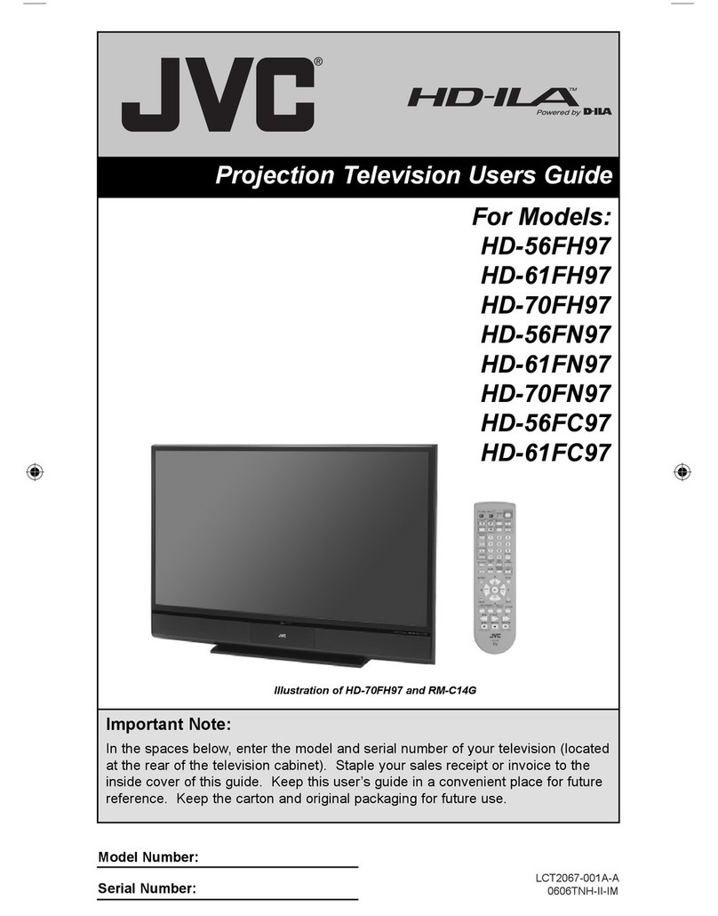
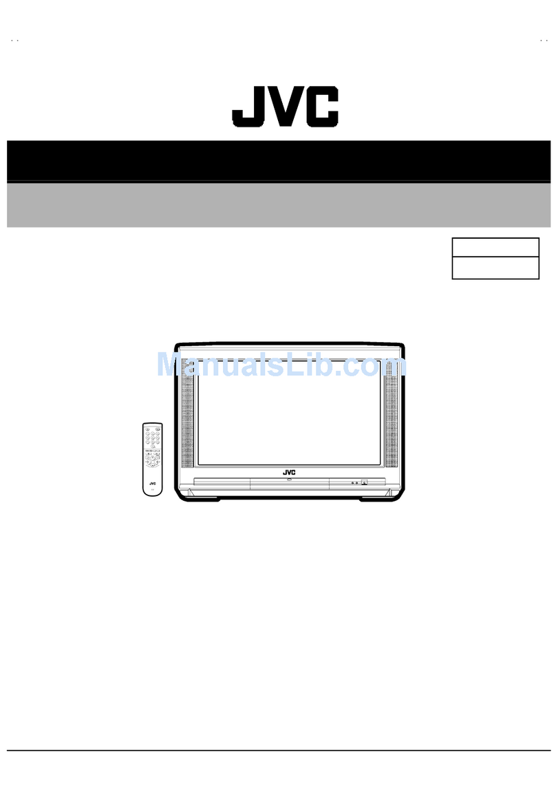
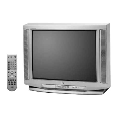
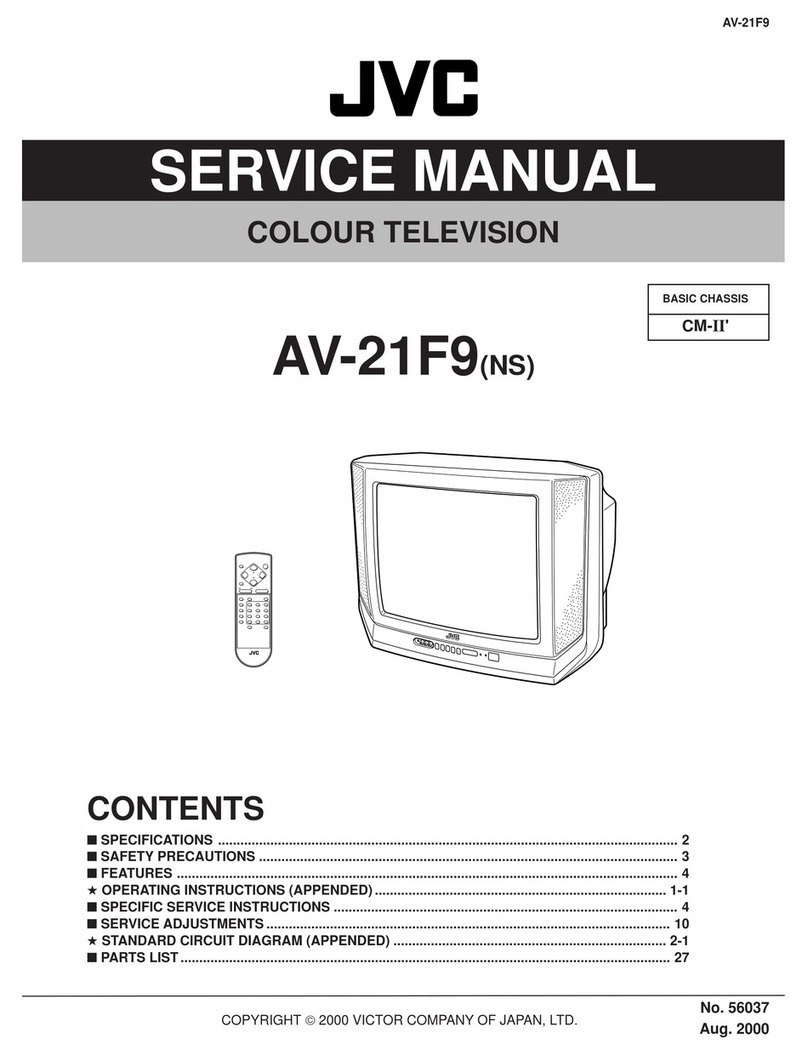
JVC InteriArt AV32H20EUS User manual

No.51945
AV32H20EU
S
AV28H20EU
S
AV28H20EU
B
1COPYRIGHT © 2002 VICTOR COMPANY OF JAPAN, LTD.
May 2002
AV32H20EUS
AV28H20EUS
AV28H20EUB
CONTENTS
!SPECIFICATIONS ・・・・・・・・・・・・・・・・・・・・・・・・・・・・・・・・
・・・・・・・・・・・・・・・・・・・・・・・・・・・・・・・・・・・・・・・・・・・・・・・・・・・・・・・・・・・・・・・・
・・・・・・・・・・・・・・・・・・・・・・・・・・・・・・・・・・・・・・・・・・・・・・・・・・・・・・・・・・・・・
・・・・・・・・・・・・・・・・・・・・・・・・・・・・・・・・・・・・・・・・・・・・・・・・・・・・・・・・・・
・・・・・・・・・・・・・・・・・・・・・・・・・・・・・ 2
!SAFETY PRECAUT IONS ・・・・・・・・・・・・・・・・・・・・・・・・・・・・・・・・
・・・・・・・・・・・・・・・・・・・・・・・・・・・・・・・・・・・・・・・・・・・・・・・・・・・・・・・・・・・・・・・・
・・・・・・・・・・・・・・・・・・・・・・・・・・・・・・・・・・・・・・・・・・・・・・・・・・・・・・・
・・・・・・・・・・・・・・・・・・・・・・・・・・・・・・・・・・・・・・・・・・・・・・
・・・・・・・・・・・・・・・・・・・・・・・ 4
!FEATURES・・・・・・・・・・・・・・・・・・・・・・・・・・・・・・・・
・・・・・・・・・・・・・・・・・・・・・・・・・・・・・・・・・・・・・・・・・・・・・・・・・・・・・・・・・・・・・・・・
・・・・・・・・・・・・・・・・・・・・・・・・・・・・・・・・・・・・・・・・・・・・・・・・・・・・・・・・・・・・・・・・
・・・・・・・・・・・・・・・・・・・・・・・・・・・・・・・・・・・・・・・・・・・・・・・・・・・・・・・・・・・・・・・・
・・・・・・・・・・・・・・・・・・・・・・・・・・・・・・・・・・・
・・・・・・
・・・ 5
!MAIN DIFFERENCE LIST ・・・・・・・・・・・・・・・・・・・・・・・・・・・・・・・・
・・・・・・・・・・・・・・・・・・・・・・・・・・・・・・・・・・・・・・・・・・・・・・・・・・・・・・・・・・・・・・・・
・・・・・・・・・・・・・・・・・・・・・・・・・・・・・・・・・・・・・・・・・・・・・・・・・・・・・・・
・・・・・・・・・・・・・・・・・・・・・・・・・・・・・・・・・・・・・・・・・・・・・・
・・・・・・・・・・・・・・・・・・・・・・・ 5
!SPECIFIC SERVICE INSTRUCTIONS ・・・・・・・・・・・・・・・・・・・・・・・・・・・・・・・・
・・・・・・・・・・・・・・・・・・・・・・・・・・・・・・・・・・・・・・・・・・・・・・・・・・・・・・・・・・・・・・・・
・・・・・・・・・・・・・・・・・・・・・・・・・・・・・・・・・・・・・・・・・・・・・
・・・・・・・・・・・・・・・・・・・・・・・・・・
・・・・・・・・・・・・・ 6
!SERVICE ADJUSTMENTS ・・・・・・・・・・・・・・・・・・・・・・・・・・・・・・・・
・・・・・・・・・・・・・・・・・・・・・・・・・・・・・・・・・・・・・・・・・・・・・・・・・・・・・・・・・・・・・・・・
・・・・・・・・・・・・・・・・・・・・・・・・・・・・・・・・・・・・・・・・・・・・・・・・・・・・・
・・・・・・・・・・・・・・・・・・・・・・・・・・・・・・・・・・・・・・・・・・
・・・・・・・・・・・・・・・・・・・・・ 12
!PARTS LIST ・・・・・・・・・・・・・・・・・・・・・・・・・・・・・・・・
・・・・・・・・・・・・・・・・・・・・・・・・・・・・・・・・・・・・・・・・・・・・・・・・・・・・・・・・・・・・・・・・
・・・・・・・・・・・・・・・・・・・・・・・・・・・・・・・・・・・・・・・・・・・・・・・・・・・・・・・・・・・・・・・・
・・・・・・・・・・・・・・・・・・・・・・・・・・・・・・・・・・・・・・・・・・・・・・・・・・・・・・・・・・・・・・・・
・・・・・・・・・・・・・・・・・・・・・・・・・・・・・・・・・
・・
・31
★
OPERATING INSTRUCTIONS
★
STANDAR D CIRCUIT DIAGRAM ・・・・・・・・・・・・・・・・・・・・・・・・・・・・・・・・
・・・・・・・・・・・・・・・・・・・・・・・・・・・・・・・・・・・・・・・・・・・・・・・・・・・・・・・・・・・・・・・・
・・・・・・・・・・・・・・・・・・・・・・・・・・・・・・・・・・・・・・・・・・・・・・・・
・・・・・・・・・・・・・・・・・・・・・・・・・・・・・・・・
・・・・・・・・・・・・・・・・2- 1
SERVICE MANUAL
COLOUR TELEVISION
BASIC CHASSIS
MFⅡ
ⅡⅡ
Ⅱ
All manuals and user guides at all-guides.com
all-guides.com

No.51945
A
V32H20EUS
A
V28H20EUS
A
V28H20EUB
2
SPECIFICATIONS
Content
Item
AV 32 H 20 EUS AV 28 H 20 EUS / AV 28 H2 0E UB
Dimensions ( W×
××
×H×
××
×D ) 85 5m m×5 50mm×5 68mm 78 0m m×5 09mm ×4 99mm
Mass 53 .6 kg 40 .2 kg
TV RF System CCI R (B/G ,D/K, I ,L , L ’)
Colour Sy st em PA L / SECA M / NTSC (Only in EXT mo de)
St ere o Sy st em A2 (B /G,D/K )/ NICAM (B/G, I,D/K,L )
Teletext System FLOF (Fastext)
TOP (German system)
WST(W orld Standard system)
Receiving Frequency
VHF 47 MHz ~47 0M Hz
UHF 470MHz ~8 62MHz
French CAT V 11 6MHz ~1 72MHz / 22 0MHz ~469MHz
Intermediate Frequency
VIF Carrier 38.9 MHz (B/G, I ,L)/ 33.95MHz (L’)
SIF Carrier 33.4 MHz (5 .5MHz :B/ G) / 32.9 MHz (6.0MHz:I ) / 32 .4MHz ( 6. 5MHz:L , D/K ) / 40.4 5MHz ( 6.5MHz:L ’)
Colour Sub Carrier Fr e
q
.
PAL 4.43MHz
SE CAM 4.40625MHz/4.25MHz
NT SC 3.58MHz / 4.43MHz
Power Input 220 – 240 V AC, 50Hz 220 – 240 V AC, 50Hz
Power Consumption 187W(Max) / 138W(Avg), standby : 2.6W 178W(Max) / 125W(Avg), standby : 2.6W
Aerial Input Term 75 Ωun ba lanc ed, C oaxi al
Pictur e Tube Vi si ble si ze : 7 6cm , M eas ur ed di a gon ally Vi si ble si ze : 6 6cm , M eas ur ed di a gon ally
Hi g h Vo lt ag e 31.0kV (at zerobeamcurrent)
Spe ake r (16c m×4c m) ov al typ e ×2
Au dio Output 7.5 W + 7.5 W
EX T-1/EXT-2/E XT- 3
(Input / Output)
21 -p in E ur o c onn ecto r
(SCART socket)
S/ Video Y : 1V p-p POSITIVE (Negative sync Provided, when terminated with 75Ω)
C : 0.3Vp-p (Burst signal, when terminated with 75Ω)
EXT-4 (Input) Video
Au dio (L /R )
S/ Video
1V p- p 7 5 Ω( RCA pin ja ck)
50 0m Vrms( -4dB s ) , H igh Im pe dan ce ( RCA pin jack )
Y : 1V p-p POSITIVE (Negative sync Provided, when terminated with 75Ω)
C : 0.3Vp-p (Burst signal, when terminated with 75Ω)
AUDIO OUT (Variable) 0~1 Vrms, Low Im p ed ance
( RC A pi n ja ck×2)
Headphone jack St ereo min i j ac k ( φ3.5mm)
Remote Control Unit RM-C54 H (A AA/R0 3 d r y ba tte ry×2) : (A V3 2H 20 EUS, A V2 8H20 EU S)
RM-C50(A AA/R0 3 d r y bat ter y×2) : (A V28 H20 EUB)
Design & sp eci ficatio ns ar e su bje ct to change wi thout no tice .
+1kV
-1. 5kV
All manuals and user guides at all-guides.com

No.51945
A
V32H20EUS
A
V28H20EUS
A
V28H20EUB
3
■
■■
■21-pin Euro connector (SCART socket) : EXT-1 / EXT-2 / EXT-3
(P-P= Peak to Peak, B-W= Blanking to white peak)
Pin
No . Signal Designation Matching Value EXT-1 EXT-2 EXT-3
1 AU DIO R o ut put 50 0m Vrms( Nom ina l),
Low impedance
○
(TV OUT)
○
(LINE OUT) NC
2 AU DIO R in put 50 0m Vrms( Nom ina l),
Hig h impe da nce ○○○
3 AU DIO L o utp ut 50 0m Vrms( Nom ina l),
Low impedance
○
(TV OUT)
○
(LINE OUT) NC
4 AUDIO GND ○○○
5 GND (B) ○○○
6 AUDIO L input 500mVrms(Nominal),
Hig h impe da nce ○○○
7Binput 700mV
B- W , 75Ω○○NC
8 FUNCTION SW
(SLOW SW)
Low : 0-3V, High : 8-12V, High
impedance
○○○
9 GND (G) ○○○
10 SCL3 NC ○NC
11 G in put 70 0mVB- W , 7 5Ω○○NC
12 SDA3 NC ○NC
13 GND (R) ○○○
14 GND (YS)○NC NC
15 R / C input R : 700mVB- W , 75Ω
C : 300mVP- P , 75Ω
○
(only R)
○○
(only C)
16 Ys in put Low : 0 - 0.4, High : 1 - 3V, 75Ω○ NC NC
17 GND(VIDEO output) ○○○
18 GND(VIDEO input) ○○○
19 VIDEO ou tpu t 1V P- P( Nega ti ve g oi n g sync ), 75 Ω○
(TV)
○
(LINE OUT) NC
20 VIDEO / Y inp ut 1VP- P( Nega ti ve g oi n g sync ), 75 Ω○ ○ ○
21 COMMON GND ○○○
[Pin assignment]
All manuals and user guides at all-guides.com

No.51945
A
V32H20EUS
A
V28H20EUS
A
V28H20EUB
4
SAFETY PRECAUTIONS
1. The d esi gn of th is pr od uct con ta in s sp eci al har d wa re , ma ny
circuit s and components specially for safety purposes. For
con ti nu ed prot ecti on , n o chan g es sh ou ld b e ma de to the o rig i nal
d esi gn un less a uth or ized i n writi n g by th e ma nu fact ur er.
Rep lacem en t p ar ts m ust b e id ent ic al to thos e u sed in th e origin al
ci rcu it s. S er vi ce sho ul d b e p er for med by qu al if i ed p ers on nel
on ly.
2. Al te r ati on s of t he desig n or ci rcui tr y of t he pr od ucts sh ould not be
made. Any design alterations or additions will void the
m anu fact urer 's w arr a nt y and w ill f ur th er r elieve t he ma nu factu r er
of r esp onsi b ility for per so na l i njury or p r op er ty d am ag e r esul t in g
th er efr om .
3. M an y e lectr ical an d m ech ani ca l p ar ts i n th e pr od ucts ha ve
special safety-related characteristics. T hese characteristics are
oft en no t e viden t f rom visua l i nsp ecti on n or ca n t he pro tect io n
aff or de d by th em nece ssar il y b e ob tai n ed b y u sin g r ep lacemen t
com po ne nts ra ted f or hig he r vo l tag e, w att ag e, etc. Rep l acem en t
p arts wh ic h ha ve th ese sp eci al s afet y ch ar act er ist ics ar e
identified in the parts list of Servic e manual. El ec tric al
components having such features are identified by shading
on the sche matic s and by (!
!!
!) on the parts list in Service
manual. The us e of a sub sti tu te rep la cem en t whi ch do es n ot
h ave th e same saf ety ch ar act er ist ics as t he r eco mmen de d
r eplac em ent part sh own i n th e p ar ts l ist of S er vi ce m an ual m ay
cause shock, fire, or other hazards .
4. Do n't shor t between the LIVE side ground and ISOL ATED
(NEUTRAL) side ground or EARTH side ground when
repairing.
Some model's power circuit is partly different in the GND. The
diff er enc e of th e G ND is sho wn b y th e LIV E : (") side GND, the
ISO LATE D(N EUTRAL) : (#) side G ND and EARTH : ($) side
GN D. Do n't sh or t b et we en th e LIV E si d e GN D an d
ISO LATE D(NEUTRAL) side GND or EARTH side GND and
n ever m ea sur e w it h a m ea sur ing a ppa r atus ( osci llo scop e etc.)
th e LI VE sid e GND an d IS OLA T ED(N E UTRAL ) sid e G ND or
EARTH side GND at the s ame time.
If above note will not be kept, a fuse or any parts will be broken.
5. If any repair has been made to the chassis, it is recommended
th at t he B1 set ti ng shou l d b e ch ecke d or adju ste d ( Se e
ADJUSTMENT OF B 1 POW E R SU PPLY).
6. The hi gh volta ge app lie d t o th e pi ctu r e tu be mu st con for m w it h
th at sp ecifi ed in S er vi ce man ual. E xcessi ve h igh vo lt ag e ca n
cau se an incr e ase i n X- Ray em issi on , ar cing an d possib le
component damage, therefore operation under excessive high
voltage conditions should be kept to a minimum, or should be
prevent ed. If s ever e arc ing occurs, r emove t he AC power
immed iate l y an d de ter mi ne th e ca use b y vi sua l insp ect io n
( in cor rect in stal lat ion, cr acke d or m elte d high vo lt age har n ess,
p oor so ld er ing, et c.) . T o m aint ai n the p r ope r min imu m l e vel of
sof t X- Ray em ission, c omp on en ts i n th e hi gh vol tag e circui tr y
incl ud ing t he pi ct ur e tu be must b e t he e xact r ep lacem e nts or
alte rn at i ves ap pr ove d b y th e ma nuf act ur er of th e c om plet e
pr od uct.
7. Do not c hec k high volt ag e b y drawing an ar c. Use a high volt ag e
m eter or a hi g h v oltag e pr ob e wit h a V T VM. D ischa rg e th e
picture tube before attempting meter connection, by connecting
a clip le ad to th e gr ou nd f ra me a nd c onn ecti n g th e oth er end of
the lead through a 10k
Ω2W resi sto r to the an od e b utt on .
8. W hen se r vice i s r equ ir e d, ob ser ve th e or igina l l ea d dr ess. E xtr a
pr ec aut ion sh ou ld b e g i ve n t o assur e cor rect l ea d dr ess in th e
hig h voltag e ci rcui t a r ea. W her e a s hor t ci rcui t h as occu rr e d,
th ose co mp on ent s tha t i ndica te evi de nce of ove r hea ti ng sho ul d
b e r e place d. A l wa ys u se th e ma nuf act ur er 's r ep lacem en t
components.
9. Isolation Check
(Safety for Electrical Shock Hazard)
Af ter r e-ass emb lin g th e p r odu ct, al ways per f orm an isolat io n
ch eck on the expo sed me tal p ar ts of t he cabin et ( a nte nn a
ter m ina ls, vid eo /au di o inpu t and ou tpu t t er min als, C on tr ol kn obs,
m etal cabi n et, scr ewhe ad s, ea r ph one j ack, con tr ol shaf ts, etc.)
to be su re th e p r odu ct i s s af e t o o pe r ate with ou t d an ger of
elect rical shoc k.
(1) Dielectric Strength Test
The i so l ati on be tw een the A C pr im a ry circu it an d all me tal p ar ts
exp ose d t o th e us er , p ar ticul arly an y e xp os ed met al p art h avi ng a
r etu rn p ath to t he chass is sho uld withs tan d a vol t age of 3 000 V
AC (r.m.s.) for a period of one second.
( . . . . W it hstan d a vo lt ag e of 1 10 0V A C ( r.m. s.) t o an ap pl ianc e
r ate d up to 12 0V , an d 3 00 0V AC ( r .m. s.) to an ap pl ian ce r at ed
200V or more, for a periodof one second.)
This method of test requires a t est equipment not generally found
in t he ser vic e trad e.
(2) Leakage Current Check
Pl ug th e A C lin e c ord d ir ect l y in to th e A C ou tl et (d o n ot use a lin e
isol atio n tr ansf or mer du r in g thi s ch eck.) . Usi n g a " Lea kag e
Cur rent Teste r", me asur e th e l ea kag e cu rre nt f rom each exp osed
m etal p art of the ca bi ne t, p art icu lar ly any e xpos ed me tal p art
h aving a r e turn pa th to t he ch assis , t o a kn own go od ea rt h
gr ou nd (wa ter pi p e, e tc.) . An y leaka ge cur ren t m ust n ot e xceed
0.5mA AC (r.m.s.).
Howeve r, i n tr op ic al ar ea , th is mu st no t exce ed 0.2 mA AC
(r.m.s.).
"
""
"Alte rnat e Che ck M ethod
Pl ug th e A C lin e c ord d ir ect l y in to th e A C ou tl et (d o n ot use a lin e
isol atio n tr an sfor m er dur ing t his che ck.) . Use an AC vo lt me ter
h avi ng 1 00 0 oh ms pe r vol t or m ore sens it i vi ty i n th e fo llow ing
m ann er. Con nec t a 1 50 0Ω10W res ist or par a lle le d b y a 0 .1 5µF
AC -type c apa cit or bet we en an expo sed met al pa rt a nd a kno wn
g ood e ar th gr o un d ( wa ter pipe , etc.) . M eas ure th e A C vo lt ag e
acr oss th e r es ist or w ith th e AC vo l tm eter . M ove th e r esi stor
con nec tion to e ach exp ose d me tal par t, p art i cular ly a ny exp osed
m etal p ar t havi n g a r etu rn pat h to t he ch assi s, an d m easu r e th e
AC voltag e ac ro ss the r es ist or . No w, re ver se th e plu g i n th e AC
ou tl et and r e pe at eac h m ea sur emen t. An y vol t ag e me asu re d
must not exc eed 0.75V AC (r.m. s.). This c orre sponds to 0.5mA
AC (r.m.s.).
However, in tropical are a, this must not exceed 0.3V AC ( r.m.s.).
This corresponds to 0.2mA AC (r.m.s.).
0.15μF AC-T YPE
1500 Ω10W
GOODEARTH GROUND
PLACE THIS PROBE
ON E A CH EX PO SE D
ME T AL PA R T
ACVOLTMETER
(HAVING 1000 Ω/V,
OR MOR E SENSITIVITY)
All manuals and user guides at all-guides.com

No.51945
A
V32H20EUS
A
V28H20EUS
A
V28H20EUB
5
FEATURES
"New chassi s d esi gn ena ble us e of an i nte rac ti ve on scr een
control.
"The TELETEXT SYSTEM has a built-in FASTEXT (UK system),
TOP (German system) and W ST (world standard system)
system.
"Be caus e th is TV un i t cor resp on ds t o m ulti ple x br oa dca st, u sers
can enjoy music programs and sporting events with live realism.
In ad di tion , BI LIN GU AL pr o grams can b e h ear d in th ei r or ig in al
language.
"Users can make VCR dubbing of picture and sound by controlling
th e AV selec tor to se le ct an o pti o na l so urc e at th e EXT- 2 outp ut
sh own in fi gu re.
MAIN DIFFERENCE LIST
!ModelName
Par t Name AV32H2 0EUS AV28H20EUS AV28 H20EUB
MAIN PWB ASSY SMF-1401A-U2 SMF-1402A-U2
POWER & DEF PWB ASSY SMF-2401A-U2 SMF-2402A-U2
CRT SOCKET PWB ASSY SMF-3401A-U2 SMF-3402A-U2
FRO NT C ONT RO L PW B ASS Y SMF- 8401A- U2 SMF- 84 02 A- U2
!FRONT C ABINET ASSY LC 1037 6-020A-U LC 10662- 023A-U LC 10662- 024A-U
!DOOR LC 20 265- 01 7A-U LC 20 265- 02 4A-U
!POW ER KNOB LC 30 578- 00 7B-U LC 30 578- 00 4A-U
!REAR COVER LC10378-004B-U LC10664-003B-U LC10664-001E-U
JV C MARK LC 40 354- 00 3A-C LC 40 354- 00 1C- C
!RATING LABEL LC20379-027A-U LC20379-026A-U LC20379-025A-U
EURO LA BEL AEM 10 52-0 63-E A EM 10 52-0 64-E AEM 10 52-0 96-E
REMOTE CONTROL UNIT RM-C54H-1C RM-C50-1C
TV EXT-1 EXT-3
EXT-2
EXT-4
All manuals and user guides at all-guides.com

No.51945
A
V32H20EUS
A
V28H20EUS
A
V28H20EUB
6
SPECIFIC SERVICE INSTRUCTIONS
DISASSEMBLY PROCEDURE
REMOVING THE REAR COVER
1. U np lu g t he po we r c or d.
2. R emove t he 1 2 ( 28 ” m od els), 13 ( 32 ” m ode l) scr ews ma r ked A
as s hown in t he Fig. 1.
3. W ithdr a w t he r ear co ver to wa rd you .
REMOVING THE CHASSIS
"After removing the rear cover.
1. Sl ight l y r aise th e bo th si de s of th e c hassi s by h and and r e mo ve
th e t w o claws u nd er th e b oth si d es of the ch assis fr om t he fr o nt
cab i net .
2. W ithdr a w t he chass is backw a rd .
(If necess ary, take off the wire clamp, connectors etc.)
REMOVING THE SPEAKER
"After removing the rear cover.
1. Remove t he 2 screws marked B, and r emove th e sp eake r hol d er
as s h own in Fig. 1.
NOTE : W hen removing t he screws m arked Bof t he sp eake r
remove t he lo wer side scr ew first, an d t hen r emove th e
up per one .
2. Remove the 2 screws Ca ttac hi ng th e sp eak er .
3. Follow th e s ame st eps wh en r emoving th e oth er ha nd spe ake r.
REMOVING THE AV TERMINAL BOARD
"After removing the rear cover.
1. Remove th e 3 screws marked D as shown i n t he Fig . 1 .
2. R emove th e 2 cla ws mark ed Eunder the CHASSIS as shown in
Fig. 2.
3. Remove the AV TERMINAL BOARD slightly in the direction of
arrow Fas shown in Fig. 2.
REMOVING T HE POWER & DEF PWB
"After removing the rear cover.
"After removing the rear CHASSIS.
1. Remove th e 3 screws marked G.
2. Remove th e PO WER & DEF PW B.
CHECKING THE PW BOARD
To ch eck the b ack si de of th e PW B oar d.
1) Pull out the chassis . (Refer to REMOVING THE CHASSIS ).
2) Erect the c hassis vertically so that you c an easily check the
b ack si de of th e PW B oar d.
[CAUTION]
"When erec ting the chassis, be careful s o that there will be no
con tact in g with ot her PW Boar d.
"Be for e tur n in g on po wer , ma ke sur e t ha t the w ire co nn ecto r i s
pr op erl y con nec ted .
"W hen co ndu cti ng a ch eck w ith p ower su pplied , b e sur e to c onfir m
th at t he CRT E AR TH W I RE (B RA IDED AS S’Y) is co nne cted t o
th e CRT SOC KE T PW b oar d.
WIRE CLAMPIN G AND CABLE T YING
1. Be sure t o clamp the wire.
2. N ever r em o ve th e c abl e ti e use d f or tyi ng th e w ire s to ge the r.
Should it be inadvert ent ly removed, b e sure to tie the wires with
a n ew c abl e ti e.
AV SW PW B
E
Fig. 2
AV TERMINAL
BOARD
E
All manuals and user guides at all-guides.com
all-guides.com

No.51945
A
V32H20EUS
A
V28H20EUS
A
V28H20EUB
7
Fig. 1
REAR COVER
FRONT CABINET
SP EAKE R
CRT
SOCKET
PWB
FRONT
C ONT RO L
PWB(1/2 )
MAIN
PWB
POWER & DEF.
PWB
CLAW
CLAW
CHASSIS
AV TERMINAL
BOARD
B
POWER CORD
C
(
×2
)
A
(×13 : 32” m od el)
D
(
×3
)
(
×2
)
FRONT
C ONT RO L
PWB(2/2 )
AV SW
PWB
Thi s explo de d view descr ibe s ab out
AV 28H2 0EUS / AV 28 H2 0EUB.
Al th ou gh AV 32 H 20E US ar e slight l y
diff er ent from t his f igure, you c an use
th e e xpl od ed vi ew f or di sass em bli ng
th e A V32 H20E U S in same ste p as
AV 28H2 0EUS / AV 28 H2 0E UB .
(×12 : 28” m od els)
G
(
×3
)
MICOM PWB
1
00
Hz PWB
All manuals and user guides at all-guides.com

No. 51945
A
V32H20EUS
A
V28H20EUS
A
V28H20EUB
8
REMOVING THE CRT
∗Rep lacem en t of th e CR T sho uld be p er for med b y 2 or m ore
p ers ons.
•Af ter removing the c over, chassis etc.,
1. Pu tting th e CR T c han ge ta bl e o n sof t cl oth , th e C RT cha ng e ta bl e
sh ould also b e c over ed with s uch soft clot h (shown in Fig. 3) .
2. W hile kee pi n g th e s urf ac e of C RT down , m ou nt the TV s et o n t he
CRT change table balanced will as shown in Fig.4.
3. Rem ove 4 sc re ws mar ke d by arro ws with a b ox typ e scr e w dr iver
as s hown in Fig. 4.
•Si nc e th e cab inet will drop w h en screws h ave b een r em o ve d, b e
sure t o su pp ort t he cabin et with h an ds.
4. After 4 screws have been removed, put the cabinet slowly on
cloth (At this time, be carefully so as not to d amage th e front
sur fac e of th e c abi n et) sh ow n i n F ig.5 .
•The C RT sh ould b e ass em bled accor din g to th e o pp osi te
sequence of its dismounting steps.
∗The C RT cha ng e t ab le sh oul d pr ef er ab ly b e sm all er t hat th e CRT
sur fac e, and i ts h eigh t b e abo ut 35c m.
CRT CHANGE TABL E
CLOTH
AP PROX.
35 cm
CRT
CRT
CHANGE
TABLE
BOX
TYPE
SCREW
DRI VER
Fig. 3
Fig. 5
CRT
CABINET CRT
CHANGE TABLE
Fig. 4
All manuals and user guides at all-guides.com

No.51945
A
V32H20EUS
A
V28H20EUS
A
V28H20EUB
9
REPLACEMENT OF CHIP COMPONENT
!CAUTIONS
1. Avoid heating for more than 3 seconds.
2. D o n ot ru b t he el ect ro des an d t he r esist p ar ts of th e p att ern.
3. W hen r em ovi ng a c hip par t, m elt th e s ol der ad equ ate l y.
4. D o n ot r euse a ch i p p ar t afte r re mo vi ng it .
!SOLDERING IRON
1. Use a hig h ins ulatio n s older ing iron with a t hin po in ted e nd of it .
2. A 3 0 w s ol dering i ron is r ec om mend ed for easily r em oving p ar ts.
!REPLACEMENT STEPS
1. How to remove Chip parts
#
##
#Resi st ors, ca pa cit ors , et c
( 1) As sh own i n t he f ig ur e, pu sh th e pa rt w ith tw ee zer s and
alte rn at el y m elt th e sol de r at each en d.
( 2) Sh if t w ith tweeze rs an d r emo ve th e ch ip p ar t.
#
##
#Trans ist ors, diod es , va ria bl e r es ist or s, et c
( 1) Ap ply e xt ra so ld er to ea ch l e ad .
( 2) As sh own i n t he f ig ur e, pu sh th e pa rt w ith tw ee zer s and
alte rn at el y m elt th e sold er a t each l e ad . S hi ft an d r emove t he
chip part.
Note : A fter removing t he part , remove remaining solder from the
pattern .
2. How to install Chip parts
#
##
#Resi st ors, ca pa cit ors , et c
(1) Apply sold er to th e pattern as indic ated in the fig ure.
( 2) Gr asp t he ch ip p art wi th tw ee zer s and pl ac e i t on th e s ol d er.
The n h ea t an d me lt th e so ld er a t b oth en ds of t he chi p par t.
#
##
#Trans ist ors, diod es , va ria bl e r es ist or s, et c
(1) Apply sold er to th e pattern as indic ated in the fig ure.
( 2) Gr asp th e ch ip p art w it h t we eze rs an d p lace it on th e so l der.
(3) First s older lead Aas indicated in t he figure.
( 4) The n so ld er l e ads Band C.
SOLD E R SOLD E R
A
B
C
A
B
C
All manuals and user guides at all-guides.com

No. 51945
A
V32H20EUS
A
V28H20EUS
A
V28H20EUB
10
REPLACEMENT OF MEMORY ICs
1. Memory ICs
This TV use memory ICs. In the memory ICs, there are memorized data
for corr ectl y op er ati n g th e vid eo an d def lecti on circu its . W h en r ep laci ng
memor y ICs, b e s ure t o us e ICs writte n with th e initial values of da ta.
2. Procedure for replacing memory ICs
PROCEDURE
(1) Power off
Sw itch the p ow er of f an d un pl ug th e p ow er cord f ro m t he ou tlet.
(2) Repla ce ICs.
Be sure to use memory ICs written with the initial data values.
(3) Power on
Pl ug th e p ower c or d int o th e ou tlet a nd sw it ch t he po we r on .
(4) Check and s et SY STEM CO NSTANT SET :
*
**
*
It must not adjust without s ignal.
1) Pr ess th e IN FO RMATI ON ke y an d th e MUTIN G key of th e
REMOTE CONTROL UNIT simultaneously.
2) The SERVICE MENU screen of Fig. 1 will be displayed.
3) W hile th e S ER VIC E ME NU is d is pl aye d, pr es s th e
INFORMA TION key and MUTING key s imult aneously, and t he
SYSTEM CONSTANT SET screen of Fig. 2 will be display ed.
4) Check th e se tting va lu es of the S YSTEM CONSTA NT SET of
Table 1. If th e value is d if ferent, select th e s etting item with th e
FUNCTION UP/ DOWN key, and s et t he c orrect va lue with the
FUNCTION -/+ key.
5) Press the MENU key to memorize the setting value.
6) Pr ess t he IN FOR MATION ke y t wi ce, a nd r etu rn t o th e no rmal
screen.
(5) Se tting of re cei ve ch anne ls
Se t th e r ec eive ch an ne l.
For setting, refer to the OPERATING INS TRUCTIONS.
(6) User se tt ings
Check th e us er sett in g val ues of Tab le 2, an d if sett in g value i s
diff er ent , set th e c orr ec t val u e.
For setting, refer to the OPERATING INS TRUCTIONS.
(7) Setting of SERVICE MENU
Ve rif y the set ting it ems of th e SE RVICE M E NU of Tab l e 3, an d rese t
where necessary.
For setting, ref er to the SERVICE ADJUSTMENTS.
Na mes of ke y
i
ii
i
▼
▼
▼
▼
INFORMATI ON
MUT ING
FUNCTION UP/ DOWN
ME NU
FUNCTION -/+
ke y
OK
NAME OF REMOTE CONTROL KEY
SE RV ICE MENU
1. IF 2. V/C
3. A UDIO 4. D EF
5. VSM PRESET 6. STATUS
7. P IP 8. -- -
9. SHIPPING (OFF) 0. BUS FREE
1 -9 : SE LE CT
i
: EXIT
Fig.1
SYS T EM C ONS TA NT S ET
1. DESTINATION EU
- /+ : STORE i : EXIT
Fig.2
OK
All manuals and user guides at all-guides.com

No. 51945
A
V32H20EUS
A
V28H20EUS
A
V28H20EUB
11
SETT ING VALU ES OF SYST EM CONSTANT SET (TABLE 1)
Setting item Setting content Settin
g
value Setting item Setting content Settin
g
v alue
DESTINATION EU DOLBY NO
CRT TYPE 16 :9 BB E YE S
PURITY NO PROGRESSIVE NO
PICTURE TILT YES TDA9178 NO
DIGIP URE PRO NO TONE I C NO
PIP NO FLAT YE S
PIC&TE XT NO
USER SETTING VALUES (TABLE 2)
PICTURE SE TTING EX T SETTI NG
TINT COOL
CONTRAST / BRIGHT
SHARP / COLO UR
ID
S-IN
DUBBING
BLANK
BLANK
EXT-1→EX T-2
PICTURE FEATURES FEATURES
DIGITA L VNR AUTO
COLO UR S YSTE M TV : Acco rd in g t o p reset CH
EXT : AUTO
4:3 AUTO ASPE CT PA NO RA MIC
SL EEP TIME R
BL UE BA CK
OFF
ON
SOUND SETTING INSTALL
BA SS / TR EBLE / BA LANCE LA NG UA GE ENGL ISH
HYPE R S OUND
BB E
OFF
ON
EDIT/MANUAL PRESET CH only
The ot her s : BLA NK
SERVICE MENU SETING ITEMS (TABLE 3)
Setting item Setting value Setting item Setting value
1. IF
1. VCO
2. ATT ON/OFF
4. DEF.
1. V-SHIFT
2. V-SIZE
3. H-CENT
4. H -S IZE
5. TRAPE Z
6. EW -PIN
7. COR-PIN
8. COR-UP
9. COR-LO
10. ANGL E
11 . BOW
12. V-S.CR
13 . V- LIN
2. V / C
1. RGB BL K
2. W DR R
3. W DR G
4. W DR B
5. BRIGHT
6. CONTRAST
7. COLO UR
8. HUE
9. SHARP
10. VCO A DJ .
11. VID AGC
12 . SY C SL I
13 . A M OV IE
3.A UDIO
(Do not adjust)
1. ERR LI MIT
2. A2 ID THR
3. Q-PEA K
9.S HI PPI NG
(Do not adjust) ON/OFF
5. VSM P RE SET
COOL
NORMAL
WARM
1. CONT.
2. BRIGHT
3. SHARP
4. COLO UR
5. HUE
6. W DR R
7. W DR G
8. W DR B
6.S TATUS
(Do not adju st)
VP S
PDC
CENTER
REFER to VSMPRESET
EKEU EI
4:316 :9
YE SNO
YE SNO
YE SNO
1TUNERNO
YE S
NO
YE SNO
YE SNO
YE SNO
YE SNO
YE S
NO
YE SNO
2TUNER
*
**
*: Do not adjust
All manuals and user guides at all-guides.com
all-guides.com

No. 51945
A
V32H20EUS
A
V28H20EUS
A
V28H20EUB
12
SERVICE ADJUSTMENTS
BEFORE STARTING SERVICE ADJUSTMENT
1. There ar e 2 w ays of adjusting this TV: One is wi th the
REMOTE CONTROL UNIT and the other is the conventional
method using adjustment parts and components.
2. The setting (adjustment) using the REMOTE CONTROL
UNIT is made on the basis of th e initial setting values. The
se ttin g va lues whic h a dj ust the sc ree n to t he opt imu m
condition can be different fr om the initial setting values.
3. Make s ure th at conn ect ion is c orrect ly ma de t o AC power
sourc e.
4. Tur n on th e powe r of th e T V a nd m easu r in g instr umen t for
war min g u p f or at least 30 m in ut es b ef or e sta rt in g adj u stm ent .
5. If th e r ec ei ve or inp ut si g nal i s not sp ecifi ed , use t he m ost
ap pr op ria te s ig na l f or a dj ust me nt.
6. N ever tou ch p ar ts (such as var iab le r esist or s, tr an sfor m ers an d
condensers) not shown in the adjustment items of this service
adjustment.
7. Pr ep ar atio n f or ad justm en t (pr es etti n g):
Unless oth er wis e sp eci fied i n th e a djust me nt it em s, p rese t th e
follo win g fu nct ions with th e REMOTE CO NTROL UNI T.
"Setting p osit ion
PICTURE MODE (VSM) NORMAL
SLEEP TIMER OFF
TONE BALANCE CENTER
ZO OM FUL L
MEASURING INSTRUMENT AND FIXTURES
1. DC voltmeter (or digital voltmeter)
2. Oscilloscope
3. Sign al g enerat or (P att ern gen erat or) [ PAL / SE CA M / NTSC]
4. Remote control unit
ADJUSTMENT ITEMS
●Check in g it ems.
●Adjustment of FOCUS & SCREEN
●VS M p r eset ad ju st s etti n g.
●VIDEO / CHROMA circ uit adjustment.
●DEFLECTION c ircuit adjustment.
●AUDIO circuit adjustment. (Do not adjust)
All manuals and user guides at all-guides.com

No. 51945
A
V32H20EUS
A
V28H20EUS
A
V28H20EUB
13
ADJUSTMENT LOCATIONS
E1
CN014
CN013
TP-E
CRT SOCKET PWB
(
SOLDER SIDE
)
TOP
FRON T
MAIN PWB POWER&DEF PWB
FRON T
CN001
AV SEL PWB
TUNER
CN002
WDEG
1pi n:B1(T P-91)
2pi n:NC
3pin:X-ray
4pin:X-ray
5pi n:T P-E
5
1
X
FRONT CONTROL PWB
(
1/2
)
FRON T
HV
TP-47B
CN014
CN013
SP R
PW
F901 POWER SW
SP L
MIC OM
100Hz
CN002
F
JJ
CN004
CN005
CN006
TP-Y
FRONT CONTROL PWB
(
2/2
)
FO CUS 2
SCREEN
FO CUS 1
32"MODEL
SCREEN
FO CUS
28"MODEL
UP DOWN
S
REMOCONLED
VL
HP R
HVT
All manuals and user guides at all-guides.com

No. 51945
A
V32H20EUS
A
V28H20EUS
A
V28H20EUB
14
BASIC OPERATION SERVICE MENU
1. TOOL OF SERVICE MENU OPERATION
Operate the SERVICE MENU with the REMOTE CONTROL UNIT.
2. SERVICE MENU ITEMS
W ith the SERVI CE M ENU, var iou s sett in gs (ad ju stm en ts) c an b e m ade , a nd th ey a re b r oad ly c la ssif ied i n th e f ol lowing i te ms of set tings
(adjus tments ):
(1) 1. IF ・・・・・・・ ・・・・・・・・・・・・・ ・・・ This mod e a djust s the se tting valu es of th e I F circu it .
(2) 2.V /C ・・・・・・・ ・・・・・・・・・・・・・ ・・ This mode adjust s the setting valu es of the VIDEO / CHRO MA circuit.
(3) 3.AUDIO・・・・・・・ ・・・・・・・・・・・・ This mode adjusts the setting values of the multiplicity SOUND circuit.
(4) 4. DEF ・・・・・・・ ・・・・・・・・・・・・・ ・ This m od e adj ust s th e se tti ng val u es o f th e DE F LECT ION circui t f or eac h as pect m od e g i ve n be lo w.
FULL (100/120Hzi)
PA NO RA MIC ( 100 /12 0H z i )
SUBTITLE (100/120Hzi)
COMP RE SS (Fi xed va lu e) ( 100 /1 20Hzi )
(5) 5.V SM PR ESE T・・・・・・・ ・・・・・・ This m od e adj ust s th e in iti a l s ett in g va lues of CO OL, N ORM AL an d W ARM .
(VSM : Video Status Memory)
3. BASIC OPERATION OF SERVICE MENU
(1) How to enter SERVICE MENU
Press the “INFORM ATI ON” key and th e “MUT ING” key of the
REMOTE CONTROL UNIT simultaneously, and the
SERVICE MENU screen of Fig.1 will be displayed.
(2) Selection of SUB MENU SCREEN
Press one of keys 1~5 of the REMOTE CONTROL UNIT
an d sele ct th e S UB M ENU S C REEN ( See F ig. 3 ), fo rm th e
SERVICE MENU.
SERVICE MENU →SUB ME NU
1. IF
2. V / C
3. AUDIO
4. DE F.
5. VS M PRESE T
6. STATUS
7. PI P
8. ---
9. SH IP PING ( OFF)
0. BUS FREE
Names of ke
y
i
ii
i
▼
▼
▼
▼
INFORMATION
MUT ING
FUNCTION UP/DOWN
ME NU
FUNCTION -/+
ke
y
OK
SE RV ICE MENU
NAME OF REMOTE CONTROL KEY
Fig.2
SE RVIC E ME NU
1. IF 2. V/C
3. AUDIO 4. DEF
5 . VS M PRES ET 6. ST ATUS
7. PIP 8. ---
9. SHI PP ING (OFF) 0 . BU S FREE
1-9 : SEL ECT
i
: EXIT
Fig.1
*
**
*: Donotadjust
All manuals and user guides at all-guides.com

No. 51945
A
V32H20EUS
A
V28H20EUS
A
V28H20EUB
15
1. RGB BLK
2. WDR R
3. WDR G
4. WDR B
5. BRIGHT
6. CONTRAST
7. COLO UR
8. HUE
9. SHARP
10.VCO ADJ
11.VID AGC
12.SYC SLI
13.A MO VIE
SE RVICE M ENU
V/C
1. RGB_BLK
****
2. V/C
PAL
- / + : STORE i : EXIT
DE F *** Hz FULL
1. V- SHIFT
4. DEF
***
- / + : STORE i : EXIT
1. V- SHIFT
2. V- SIZE
3. H-CENT
4. H-SIZE
5. TRAPEZ
6. EW -P IN
7. COR-PIN
8. COR-UP
9. COR-L O
10.A NGLE
11.B OW
12 .V- S.CR
13.V-LIN
IF S ER VICE MENU
1. VCO
2. AT T ON/ O FF
1-2 : SELECT i : EXIT
SERVI CE MENU
1. IF 2. V/C
3. AUDIO 4. DEF
5. VSM PRESET 6. STATUS
7. PIP (O FF) 8. - - -
9. SHIPPING (OFF) 0. BUS FREE
1-9 : SELECT : E XITi
1. ERR L IMIT
2. A2 ID THR
3. Q P EAK
AUDIO
3. AUDIO
1. ERR LIMIT 100H
ERROR RATE =
* ** *** **
- / + : STORE i : EXIT
1.IF(V CO)
COOL
NORMAL
WARM
5. VSM PRESET
VSM PRESET NORMAL
1.CONT
***
- / + : STORE i : EXIT
1. CONT.
2. BRIGHT
3. SHARP
4. COLO UR
5. HUE
6. WDR R
7. WDR G
8. WDR B
Do not move
Do not adjust
OK
OK
OK OK
Fig.3 SUB MENU SCREEN
All manuals and user guides at all-guides.com

No. 51945
A
V32H20EUS
A
V28H20EUS
A
V28H20EUB
16
( 3) M eth od of Set ti ng
1) Meth od of Set ti ng 1. IF
[VCO] ・・・・・・・ ・・・・・・・・・・・・・ ・・・・・・・・・・・・ ・・・ It mus t not adjust without signal.
①1 K ey・・・・・・・ ・・・・・・・・・・・・・ ・・・・・・・・・・・・ Select 1.IF.
②1 K ey・・・・・・・ ・・・・・・・・・・・・・ ・・・・・・・・・・・・ Se lect 1 .VCO(CW)
Makesurethat thearrow positionbetween the ABOVE REFandBELOW REF.
③INFORMATION K ey ・・・・・・・ ・・・・・・・・・・・・ Return t o the SERVICE ME NU screen.
2) M eth od of s ett in g 2.V/C, 3.AUDIO, 4.DEF an d 5 .VSM PRESET.
①2~5 K ey・・・・・・・ ・・・・・・・・・・・・・ ・・・・・・・・・ Select one from 2.V/C, 3.AUDIO, 4.DEF an d 5.VSM PRESET.
②FUNCTION UP / DOWN ( / ) Key ・・・・・ Select s etting items.
③FUNCTION -/+ ( / ) Key ・・・・・・・ ・・・・・・ Set (adjust) the setting values of the settin g it ems.
④ME NU Key ・・・・・・・ ・・・・・・・・・・・・・ ・・・・・・・ Memorize the s ettin g value.
( Bef or e st or in g t he sett in g values in m emory, do no t pr es s th e CH, TV, POW E R ON /
OF F ke y - if you d o, t he val ue s w ill n ot be stor ed i n me mo r y. )
⑤INFORMATION K ey ・・・・・・・ ・・・・・・・・・・・・ Return t o th e SE R VICE ME NU scr ee n.
3) Do not setting6.STATUS, 7.PIP, 8.--- , 9.SHIPPING(OFF) & 0.BUS FREE.
(4) Rele as e of SER V IC E M E NU
1) Af ter co mp l eting th e se tting , r et ur n t o t he SERVIC E ME NU , th en ag ain p r ess th e I NFOR MATIO N ke y.
All manuals and user guides at all-guides.com
all-guides.com

No. 51945
A
V32H20EUS
A
V28H20EUS
A
V28H20EUB
17
ADJUSTMENTS
CHECK IT EM
Item Measuring
instrument Test
p
oint Ad justment part Description
B1
Powe r Su
pp
l
y
che ck
Signal
generator
DC v o ltm et er
Remote
control unit
TP-91(B1)
TP-E(#
##
#)
[X connector
on POWER
DE F PW B ]
1.R G B BL K 1. Recei ve a an y br oa dca st.
2. Pu sh t he “ZOOM ” ke y an d s elect the FULL m ode .
3. Select 2 . V/C from the S ERVICE ME NU.
4. Select 1 . RGB BLK with f unction UP / DOWN ( / ) key.
5. Press the function + ( ) key to find the cut off screen (Black
screen).
6. C on nect a DC voltm et er t o TP- 9 1(B 1) a nd TP- E( #).
7. M ake sur e t hat th e volt ag e is DC13 9.9 ±2.0V.
8. Press the function – ( ) key t o return to service menu..
Hi g h Vo lt ag e
che ck
Signal
generator
DC volunteer
Remote
control unit
CRT anode
Chass is
GND
1.R G B BL K 1. Recei ve a an y br oa dca st.
2. Pu sh t he “ZOOM ” ke y an d s elect the FULL m ode .
3. Select 2 . V/C from the S ERVICE ME NU.
4. Select 1 . RGB BLK with f unction UP / DOWN ( / ) key.
5. Press the function + ( ) key to find the cut off screen (Black
screen).
6. Connect a DC voltmeter to CRT ANODE and chassis GND.
7. M ake sur e t hat th e volt ag e is DC 3 1.0 kV .
8. Press the function – ( ) key t o return to service menu.
VC O ch ec k Remote
control unit
1. VCO "Und er n orma l c ond i tions, no ad just me nt i s r e quir ed .
"Conf irm at io n a djust me nt.
1. Select 1 .IF f rom t he SERV ICE MENU.
2. Then se lect 1 .VCO from th e IF S ERVICE MENU.
3. R ecei ve an y br o adc ast.
4. C heck t he a rrow ( ←
←←
←) p osi tion be tw een th e AB OVE R EF . an d
BE LOW REF.
+1kV
-1.5kV
TO O HI GH
ABOVE REF
JUST REF
BELOW REF
TO O LO W
i : EXIT
VCO(CW)
****
MHz
MAI N
1. VCO
2. ATT ON/OFF
i : EXIT
IF SERVIC E MEN U
1-2 : SELECT
(Do not move)
All manuals and user guides at all-guides.com

No. 51945
A
V32H20EUS
A
V28H20EUS
A
V28H20EUB
18
FOCU S & SCREEN ADJUSTMENT
Item Measuring
instrument Test point Ad justment part Description
FOCUS
adju stme nt
[28” MODEL]
Signal
generator
FOCUS VR
[In HVT]
[28”MODEL]
1. R ecei ve a cr oss -h atc h si gn al.
2. Press the “ZOOM” key and s elect the FULL mode.
3. W hile w atc hi ng th e scr een , a dj ust th e FOC US VR to m ake th e
ver ti cal and ho rizo nta l lin es as f in e a nd sha rp as possi b le.
4. M ake sur e th at when the sc re en is d ar ke ned , the l ines r e ma i n
in good focus.
FOCUS
adju s tme nt
[32” MODEL]
Signal
generator
FOCUS 1
FOCUS 2
[In HVT]
[32”MODEL]
1. Receive a cr oss- h atch signa l.
2. Pu sh t he “ZOOM ” ke y an d s elect the FULL m ode .
3. By t ur nin g th e FOC US2 VR , and a dj ust t he p ict ur e s o tha t th e
“ “ part vertical line may become thinnest.
4. By t ur nin g th e FOC US1 VR , and a dj ust t he p ict ur e s o tha t th e
3r d h or izont al line fr om t he upp er m ay bec om e un i for m a t th e
lin e c ent er an d its pe riph er y.
5. C arry out ad j ustm en t b y r ep eat in g the ste ps 3 an d 4 ab ove .
6. M ake sur e th at when the sc re en is d ar ke ned , the l ines r e ma i n
in good focus.
SCREEN
Ad ju st men t
Signal
generator
SCREENVR
[In HVT]
1 Pr ess a w h ole b la ck si gn al
2 Press the “ZOOM” key and select the FULL mode.
3 Select 2. V/ C from the SERVICE MENU.
4 Tur n t he SCREEN V R clockwis e f rom th e f ull co unt er
cl ockwis e p osi tion an d st op i t a t th e po int wh er e “ CLOW ” stat us
(marke d in Fig.) ch ang es f rom 1 t o 0 to 1 ( wh ich is
indic ated at the 3rd colu mn from the right.)
5 The n t ur n th e SC RE EN V R cou nt ercl o ckwis e, an d st op wh er e
th e “ CLOW ” stat us ch an ges 1 t o 0
*“ CLOW ” : c ontr o l l oop ou t of win do w.
SCREEN VR
HVT
FOCUS VR
V/C
1. RGB BLK
00
CLOW
statu s
- / +
: STORE i : EXIT
OK
0 0 0 0 0 1 0 0
PAL
SERVICE MODE SCREEN
FOCUS1(F1)
SCREEN1(S1)
FOCUS2(F2)
HVT
FOCUS 2
FOCUS 1
All manuals and user guides at all-guides.com

No. 51945
A
V32H20EUS
A
V28H20EUS
A
V28H20EUB
19
VSM PR ESET AD JUST SET TIN G
Item Measurin
g
instrument Test point Ad justment part Description
VS M PRE SET
se ttin g
Remote
control unit
1. CONT .
2. BR IG HT
3. SHARP
4. COLOUR
5. HUE
6. W DR R
7. W DR G
8. W DR B
1. Select CO OL with the MENU key of t he re mote control unit.
2. Se le ct 5 .VS M P RESET fr om th e S ERVICE ME NU.
3. Adju st t he FUNCTIO N UP/DOWN ( / ) and -/+ ( / )ke y to
br ing th e set va l ues of 1.CON T ~8. W DR B to the va lues
sh own in th e ta bl e.
4. Pr ess the ME NU key a nd m emor iz e th e s et va lue.
5. Respectively s elect the VSM PRESET mode for NORMAL and
W ARM, an d m ake simil ar a dj ust me nt as i n 3 abo ve.
6. Pr ess the ME NU key a nd m emor iz e th e s et va lue.
*Refer t o OP ERATING I NS TRUCTIONS for th e PICTURE
MO DE .
1.CONT. 2.BRIGHT 3.SHARP 4.COLOUR 5.HUE 6.WDR R 7.WDR G 8.WDR B
COOL +16 0 -10 +1 0 -27 -12 0
32 ” NORMAL 00-1000000
WARM -13 0 -12 -1 0 +5 0 0
COOL +130 -120 0-28-12 0
28 ” NORMAL -30-1200000
WARM -13 0 -12 -1 0 +4 0 0
SE TTING VALUES OF VSM PRESET
All manuals and user guides at all-guides.com

No. 51945
A
V32H20EUS
A
V28H20EUS
A
V28H20EUB
20
VIDEO / CHROMA CIRCUIT ADJUSTMENT
The setting (adjustment) using the REMOTE CONTROL UNIT is made on the basis of the initial setting values.
The setting values which adjust the screen to the optimum condition can be different from the initial setting values.
Setting item
(Adjustment item) Initial set ting v al ue
2. V/C PAL SE CAM NT SC
1.R G B BL K
2.WDR R 00 00
3.WDR G 00 00
4.WDR B (Do not adjust) -012
5. BR IG HT 00 00
6.CONTRAST 00 60
7.COLO UR 00 00
8. HUE 00 20
9.SHARP (Do not adjust) 00 07
10.VCO ADJ. (Do not adjust)
11 .VI D AGC (Do not adjust ) 00 00
12.SY C SLI (Do not adjust) 00 07
13.A MOVIE (Do not adjust) 00 01
*
**
*: Do not adjust
All manuals and user guides at all-guides.com
Other manuals for InteriArt AV32H20EUS
3
This manual suits for next models
2
Table of contents
Other JVC TV manuals

JVC
JVC I Art PRO AV-48P777 Administrator Guide

JVC
JVC InteriArt Natural Vision T_V LINK AV28H20EU User manual

JVC
JVC AV 20F704 User manual

JVC
JVC AV-28BT8EEB User manual

JVC
JVC AV-21F1EG User manual

JVC
JVC AV-29ED5BN, AV-29ED5SN User manual

JVC
JVC LT-32WX84 User manual

JVC
JVC AV-N29702/S User manual

JVC
JVC InteriArt AV-28E50SK User manual

JVC
JVC AV 14F704 User manual