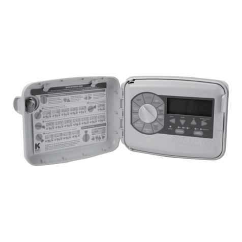
K-Rain Pro EX 2.0 User manual

INSTALLATION, PROGRAMMING AND OPERATION MANUAL
03-15_PROEX_inst guide_KRN06604_PROMinst guide.qxd 3/27/15 9:32 AM Page 1

www.krain.com
Controls and Touch Pad 02
Setting the Controller to Off 03
Set Controller to Run Automatically 03
Program Select Button 03
Rain Sensor Button 04
Programming 04
Set Current Time/Date 05
Set Program Start Times 05
Set Watering Days 06
Set Custom Operation 06
(any day of the week)
Set Odd/Even Operation 06
(calendar day)
Set Cyclic Watering Cycle 07
Set Station Run Times 07
Manual Program Operation 08
Remote/Pin 08
Running a Single Station Manually 09
Valve Locator 09
Test All Stations 10
Special Features 11
Seasonal Adjust 11
Station Delay/Overlap 11
Pump On/Off 11
Sensor 12
Open Circuit Detection 12
Clear 12
CONTENTS
This unit has been designed to provide reasonable
protection against harmful interference in a residential
install. This equipment uses, generates and can radiate
radio frequency energy and, if not installed and used in
accordance with the instructions, may cause harmful
interference to radio communications. There is no
guarantee that interference will not occur in any
particular install.
If the equipment does cause harmful interference to
radio or television reception, which can be determined
by turning the equipment off and back on again, the
user is encouraged to try to correct the interference
by (1) reorient or relocate the receiving antenna; (2)
increase the separation between the equipment and
receiver; (3) connect the equipment into an outlet on
a different circuit from the receiver; (4) consult the
dealer or an experienced radio / TV technician for help.
Changes or modifications to this equipment could
void the user’s authority to use the equipment as well
as the warranty.
INTRODUCTION
The Pro EX 2.0 is an indoor/outdoor irrigation controller.
The unit consists of a master valve/pump start, test,
common, sensor terminals and one factory installed
module which will operate four electric valves.
The controller is expandable by installing separately
purchased four station modules which are installed
internally in the controller.
Save 13
Restore 13
Display Contrast 13
Permanent Day Off 14
Program Display 15
Resetting the Controller 15
Installation 16
Door Removal 16
Main Panel Removal 16
Mounting the Controller 17
Field Wire Entrances 17
Installing Station Modules 18
Connecting Station Wires 18
Pump Start/Master Valve Wiring 19
Rain Sensor 19
Remote Programming 20
Powering the Controller 20
Specifications 21
Operating Specifications 21
Electrical Specifications 21
Dimensions 21
Troubleshooting 22
Quick Programming Reference Guide 23
Notes 24
Spare Watering Planner 25
Warranty 27
DECLARATION OF CONFORMITY
01
03-15_PROEX_inst guide_KRN06604_PROMinst guide.qxd 3/27/15 9:32 AM Page 2

02
CONTROLS AND TOUCH PAD
Installation, Programming and Operation Manual
ERROR/ALARM LED
turns on when one of
the following occurs
1Watering is suspended
by a sensor
2T e controller senses
a valve s ort circuit
3A programming error
as been made.
PROGRAM DIAL
1Used to turn t e controller
on and off and to program.
2Used to run on Automatic
and to discontinue
watering (OFF)
3Used to select desired
controller setting
functions (SET)
4S ows total content of
a program (PROGRAM
DISPLAY)
5Used to set personalized
Pin Number
(REMOTE/PIN)
6Used to allow setting
controller special
features (SPECIAL
FEATURES)
7Used to run single
stations or system
test cycles (RUN)
LCD DISPLAY
1
Displays t e time of day
and day of t e week
2
During programming
s ows t e results of
entered commands
3
During watering s ows
t e valve t at is on and
t e minutes remaining
in its run time
DOWN / UP BUTTONS
Used to set time / date and
to make program c anges.
MANUAL START /
NEXT BUTTON
Used to start a selected
irrigation program
manually, or to manually
advance watering from one
station valve to t e next.
PROGRAM SELECT
BUTTON
Used to select watering
program A, B or C.
SENSOR BYPASS
SELECT BUTTON
Used to tell t e
controller to obey or
ignore sensor input.
OFF 9:10AM
FRI
PROGRAM DIAL
MANUAL
START/NEXT
BUTTON
BACK
BUTTON
DOWN
BUTTON
UP
BUTTON
PROGRAM
SELECT
BUTTON
ERROR /
ALARM LED SENSOR
BYPASS SELECT
BUTTON
LCD DIPSLAY
03-15_PROEX_inst guide_KRN06604_PROMinst guide.qxd 3/27/15 9:32 AM Page 3

www.krain.com
SET CONTROLLER TO RUN AUTOMATICALLY PROGRAM SELECT BUTTONSETTING THE CONTROLLER TO OFF
03
1. Turn the dial to “OFF”
When the dial is in the “OFF” position no
watering occurs. The display will show “OFF,”
the time of day and day of the week.
NOTE: Pressing any button will momentarily
display t e current “REVISION NUMBER,”
“K-RAIN” or full display screen.
1.Turn the dial to “AUTO”
When the dial is in the “AUTO” position
the controller will run in automatic mode.
The display will show the selected program,
the day of the week and the time of day.
The controller will turn on automatically to
meet ANY programmed water schedules.
The Pro EX 2.0 controller has three
separate programs, A, B and C.
Multiple programs allow valves
automatic operation with different
watering days and start times.
You can program any valve to run in
one or more of the three programs.
1. To select a program, touch the
PROGRAM select button on the front
panel to select program A, B or C.
2. The display briefly shows the
program selected.
3. The selected program then appears
on the left side of the display.
4. Any programming instructions
entered will apply only to the
selected program.
OFF 9:10AM
FRI FRI 9:09AM
a
pgm
03-15_PROEX_inst guide_KRN06604_PROMinst guide.qxd 3/27/15 9:32 AM Page 4

WED 10:26
AM
A
PGM
BYPASSED
04
Installation, Programming and Operation Manual
The purpose of a rain sensor is to stop
automatic watering when sufficient
precipitation has been reached.
The rain sensor select button allows the
user to bypass the rain sensor. If a rain
sensor has been installed, and BYPASSED
has been selected, then BYPASSED will
be displayed in the upper left corner
of the LCD.
NOTE When the rain sensor select button
is in the ON position a rain sensor or wire
jumper must be installed in order to run a
program.
Refer to page 19 for further details.
A key feature of the Pro EX 2.0 controller
is its large easy-to-read LCD display.
The display is also backlit when primary
power is being supplied to the controller,
and if any buttons are pushed.
As the program dial is rotated the display
automatically changes. The flashing value
within the display can be increased or
decreased by pressing the DOWN or UP
buttons. To go back or advance to the next
value press the BACK or NEXT buttons.
Because of variations in plant watering
needs the Pro EX 2.0 controller has three
separate programming options A, B and C.
Each program is completely independent
of each other and the controller will
automatically stack programs that overlap.
This allows for all programmed watering
to occur because only one program will
run at a time and in alphabetical order.
Only one start time per program
(A, B or C) is required to operate
all stations with a run time.
The controller automatically and
numerically advances operation
to the next station without the
need or additional start times.
For additional watering, each program can
be set with up to four separate start times.
This allows for greater irrigating efficiency
when all watering can’t be done during a
single operation (cycle and soak).
NOTE: A program must contain at least
one start time, watering day(s) and one
station wit a run time in order to operate.
PROGRAMMINGRAIN SENSOR SELECT BUTTON
03-15_PROEX_inst guide_KRN06604_PROMinst guide.qxd 3/27/15 9:32 AM Page 5

1ST 8:00AM
A
PGM
START TIME 1
www.krain.com
SET PROGRAM START TIMESSET TIME / DATE
05
1. Turn the dial to SET TIME / DATE, the
LCD will display the time of day. The word
“HOURS” will be flashing in the display.
2. Press the DOWN or UP buttons to set
current hour.
3. To change minutes, press the NEXT button.
The word “MINUTES” will be flashing in
the display.
4. Press the DOWN or UP buttons to set
current minutes.
5. To set the current date, press the NEXT
button. The word “DAY” will be flashing
in the display.
6. Press the DOWN or UP buttons to set
current day.
7. To set the current month press the NEXT
button and the word “MONTH” will be
flashing in the display.
8. Press the DOWN or UP buttons to set the
current month.
9. To set the current year press the NEXT
button. The word “YEAR” will be flashing
in the display.
10. Press the DOWN or UP buttons to set the
current year.
11. Return the dial to AUTO.
NOTE: T e
Pro EX 2.0 controller can be set for
eit er 12 or 24 our display. Pressing t e BACK
and NEXT buttons SIMULTANEOUSLY will allow
user to toggle between 12 or 24 our display.
The Pro EX 2.0 controller will allow up
to four separate watering start times for
each program.
1. Use the PROGRAM SELECT BUTTON
to select the program (A, B or C) you
wish to assign a start time.
2. Turn the dial to SET PROGRAM START
TIMES. The display will show the first start
time currently set for the selected program.
3. Press the DOWN or UP buttons to
change the start time. The time setting
change is in 15-minute increments.
4. To eliminate a watering start time press
the DOWN or UP buttons until “OFF”
appears in the display. The OFF setting is
located between 11 45 p.m. and 12 00 a.m.
5. When additional start times are needed
press the NEXT button to display the
next watering start time. Repeat steps 4
through 6 for setting additional start times.
6. Return the dial to AUTO.
9: 1 0 AM
TIME
HO RS MIN TES
2 8 F E B 1 2
FRI
DAY MONTH YEAR
03-15_PROEX_inst guide_KRN06604_PROMinst guide.qxd 3/27/15 9:32 AM Page 6

06
Installation, Programming and Operation Manual
The Pro EX 2.0 controller can be
programmed to operate within four
different watering cycles.
CUSTOM waters on the days of
the week you select.
ODD waters only on odd number
days of the month.
EVEN waters on even numbered
days of the month.
CYCLIC waters on a selected daily
interval (for example every 5 days).
1. Use the PROGRAM SELECT BUTTON
to select the program (A, B or C) you
wish to assign watering days.
2. Turn the dial to SET WATERING
DAYS. “MON ON” should appear in
the display.
3. Press the DOWN or UP buttons to
enable (ON) or disable (OFF) day of
the week operation.
4. Press the NEXT button to advance to
the next day of the week. Repeat steps
3 and 4 until all days of the week have
been set.
5. Return the dial to AUTO.
1. Use the PROGRAM SELECT BUTTON
to select the program (A, B or C) you
wish to assign odd or even watering.
2. Press the BACK and NEXT buttons
SIMULTANEOUSLY until “ODD” or
“EVEN” appears in the display.
3. Return the dial to AUTO.
SET CUSTOM OPERATION SET ODD/EVEN OPERATIONSET WATERING DAYS
O D D
A
PGM
days
e v e n
A
PGM
days
MON ON
A
PGM
DAYS
MON T E WED TH FRI SAT S N
03-15_PROEX_inst guide_KRN06604_PROMinst guide.qxd 3/27/15 9:33 AM Page 7

www.krain.com
SET STATION RUN TIMESSET CYCLIC WATER CYCLE
07
1. Use the PROGRAM SELECT BUTTON to select
the program (A, B or C) you wish to assign
cyclic watering.
2. Press BACK and NEXT buttons simultaneously
until “CYCLE” appears in the upper right corner
of the display and “DAYS REMAINING” in the
lower left. “DAYS REMAINING” will be flashing.
3. The display shows the number of days
remaining until the next watering day and
the number of days in the cycle.
4. Press the DOWN or UP buttons to set the
number of days remaining before the next
automatic watering should begin.
5. Press the NEXT button to advance to
“DAY CYCLE.” “DAY CYCLE” will be flashing.
6. Press the DOWN or UP buttons to set the
number of days in the cycle from 1 to 31.
(For example to water every 5 days set the
day cycle to “5.”)
7. Return the dial to AUTO.
Stations 1–16 can be set to run from one
second up to six hours. The first hour settings
are in one minute increments. The remaining
five hours can be set in ten minute increments.
1. Use the PROGRAM SELECT BUTTON to
select the program (A, B or C) you wish
to assign a run time.
2. Turn the dial to SET STATION RUN TIMES.
The display will show all available stations
(module must be installed). The first
available station number will be flashing.
3. Press the DOWN or UP buttons to set the
number of seconds/minutes/hours you wish
the station to operate (run time). For stations
that don’t require a run time set to “OFF.”
4. Press the NEXT button to advance to the
next station number in sequence. Repeat
steps 3 and 4 until you have set a run time
for each desired station in the selected
program.
5. Return the dial to AUTO.
NOTE: Station run times can be set to
run in eit er ours/minutes or minutes/
seconds. Press t e BACK and NEXT
buttons SIMULTANEOUSLY to toggle
between setting.
During station run time setting, if t e
next button is pressed to a station
number t at doesn’t ave an installed
module, a message indicating
“NO MOD” will appear in t e display.
0 7
A
PGM
DAYS REMAINING DAY CYCLE
CYCLE
: 1 0
A
PGM
MIN TES
STATION 1 2 3 4 5 6 7 8
R N TIME
03-15_PROEX_inst guide_KRN06604_PROMinst guide.qxd 3/27/15 9:33 AM Page 8

08
Installation, Programming and Operation Manual
MANUAL PROGRAM OPERATION
When a full program operation is needed
the user can manually start any of the three
(A, B or C) programs.
1. Use the PROGRAM SELECT BUTTON to
select the program (A, B or C) you wish
to manually operate.
2. Turn the dial to AUTO or RUN PROGRAM.
3. Press MANUAL START / NEXT button to
start the selected program.
4. The display will show “RUN,” the station
currently running and the remaining
run time for that station. As each station
completes its previously programmed
run time the next station in sequence
will begin watering.
5. Manual operation can be cancelled anytime
by turning the dial to OFF for 3 seconds.
6. Return the dial to AUTO.
NOTE: Pressing t e BACK or NEXT buttons
will manually advance to t e next or previous
station number.
Previously programmed run times can be
increased or decreased during manual
operation. Any run time c anges during
manual operation WILL NOT c ange t e
station’s stored program run time.
The Pro EX 2.0 has an optional
Handheld Remote (not included)
for convenient controller operation
eliminating back and forth trips to
the controller.
NOTE: To use t is feature t e
controller must be connected to
AC power and t e optional Remote
RF Module must be installed.
For RF Module installation, Pin Code
programming and operation please
refer to the optional Pro EX 2.0 remote
user manual.
FRI 9:09AM
A
PGM
starT
A
PGM
-
-
REMOTE PIN
03-15_PROEX_inst guide_KRN06604_PROMinst guide.qxd 3/27/15 9:33 AM Page 9

www.krain.com
VALVE LOCATORRUNNING A SINGLE STATION MANUALLY
09
When only a single station operation is needed,
the user can manually start a specific station.
1. Use the PROGRAM SELECT BUTTON to
select the program (A, B or C) that contains
the station you wish to manually operate.
2. Turn the dial to RUN SINGLE STATION.
The display will show selected program
and the word “SINGLE.” Press the NEXT
button to enter single station operation.
3. Press the UP or DOWN buttons to
select desired station.
4. Press the MANUAL START button to
begin station operation.
NOTE: Pressing t e BACK or NEXT buttons
will manually advance to t e next or previous
station number.
Previously programmed run times can be
increased or decreased during manual
operation. Any run time c anges during
manual operation WILL NOT c ange t e
station’s stored program run time.
If t e station as a zero run time (OFF) use
t e PROGRAM SELECT BUTTON to select a
different program.
Stations wit a zero run time (OFF) can not
be manually activated. Only stations wit
a previously programmed run time can be
manually started.
Locating a valve in an irrigation system
may be needed for maintenance or repair.
Without the correct tools locating the
valves can be timely.
The Pro EX 2.0 controllers locate feature
helps the user find buried valves by pulsing
the valves solenoid.
1. Turn the dial to RUN SINGLE STATION/
SYSTEM TEST. The display will show
selected program and “SINGLE.”
Press the UP or DOWN buttons until
display shows “LOCATE.”
2. Press the MANUAL START button to
begin the locate feature. The display will
now show the first available station.
3. Press the MANUAL START button to
advance to the next available station.
single
A
PGM
l o c a t e
03-15_PROEX_inst guide_KRN06604_PROMinst guide.qxd 3/27/15 9:33 AM Page 10

10
Installation, Programming and Operation Manual
The Pro EX 2.0 allows the user a quick and
simple method for checking all available
stations by running a test program. This
feature operates each station individually
in numerical order starting with the lowest
available station.
Station operation is preset for a two minute
run time which the user can alter at anytime
during the test.
1. Turn the dial to SYSTEM TEST. The display
will show selected program and “SINGLE.”
Press the UP or DOWN buttons until
display shows “TEST.”
2. Press the MANUAL START button to begin
the test feature. The display will now show
“RUN” along with its remaining run time for
the first available station.
3. To change the default test time press
the UP or DOWN buttons. While the test
program is running the display shows the
station number currently operating, along
with its remaining run time. The controller
will run each station in numerical sequence.
4. Press the NEXT button to manually
advance to the next available station.
NOTE: C anging t e test run time can be done
at anytime and for any station during t e test.
Any c ange to t e test run time becomes t e
new default for all stations.
TEST ALL STATIONS
t e s t
03-15_PROEX_inst guide_KRN06604_PROMinst guide.qxd 3/27/15 9:33 AM Page 11

www.krain.com
STATION DELAY/OVERLAP PUMP ON / OFFSEASONAL ADJUST
11
The seasonal adjust feature allows the user to
increase or decrease station run times globally,
for all stations, without re-programming each
individual station. Run times can be reduced to
as little as 10% or as high as 200%.
This feature is used to decrease or increase
watering times during seasonal temperature
changes. The seasonal adjust % is calculated
on the programmed run time for each station.
For example if a station is programmed to run
10 minutes, and the seasonal adjust is adjusted
downward 80%, the station will now run for 8
minutes. Conversely, if you set the adjustment
upwards to 120%, the same station will now
run for 12 minutes.
1. Turn the dial to SPECIAL FEATURES. Display
will show “SEASONAL ADJUST % 100.”
2. Press UP or DOWN buttons to set the
percentage in 10 degree increments.
3. Return the dial to AUTO.
The station delay / overlap feature allows the user
to insert a global time delay or overlap between
the end of any station’s watering cycle and the
beginning of the next station’s watering cycle.
Station delay is used in systems that have slow
closing valves or pump systems operating with a
slow recovery time.
Station overlap is used to reduce hydraulic over-
load (water hammer).
1. Turn the dial to SPECIAL FEATURES. Display
will show “SEASONAL ADJUST % 100.”
2. Press NEXT button to enter the delay/overlap
feature. The display will show “DELAY 0 00.”
3. Press the UP button to add a delay time. Delay
times can be set from 1 second up to 9 hours.
4. Press DOWN button to add an overlap time.
Overlap times can be set from 1 to 9 seconds.
5. Return the dial to AUTO.
The PUMP ON/OFF feature allows the user
to enable or disable the MV/PS terminal for
each individual station.
The ON/OFF feature is used in irrigation
systems where it is desirable for a pump to
operate or not operate for a specific station(s).
1. Turn the dial to SPECIAL FEATURES. Display
will show “SEASONAL ADJUST % 100.”
2. Press NEXT button until “PUMP” is displayed.
3. Press the BACK and NEXT buttons
simultaneously to enter the PUMP ON/OFF
feature. The display will show “PUMP ON”
and all stations.
4. Press the BACK or NEXT buttons to
select desired station.
5. Press UP or DOWN buttons to activate
(ON) or deactivate (OFF) the station.
6. Return the dial to AUTO.
SPECIAL FEATURES
1 0 0
seasonal adj. % P u m p
0:00
MIN TES SECONDS
DELay
03-15_PROEX_inst guide_KRN06604_PROMinst guide.qxd 3/27/15 9:33 AM Page 12

12
Installation, Programming and Operation Manual
The SENSOR on/off feature allows the user
to enable or disable the SENSOR terminals for
each individual station.
The on/off feature is used in irrigation systems
where it is desirable for a Rain Sensor to operate
or not operate for a specific station(s).
1. Turn the dial to SPECIAL FEATURES. Display
will show “SEASONAL ADJUST % 100.”
2. Press NEXT button until “SENSOR” is displayed.
3. Press the BACK and NEXT button simultaneously
to enter the sensor on / off feature. The display
will show “ACTIVE” and all stations.
4. Press the BACK or NEXT buttons to select
desired station.
5. Press the UP or DOWN buttons to activate
(ON) or bypass (OFF) the station.
6. Return the dial to AUTO.
The open circuit detection feature prevents
pump and station operation when the controller
detects an open circuit.
The open circuit detection feature can only
be enabled (ON) or disabled (OFF) globally for
all stations.
1. Turn the dial to SPECIAL FEATURES. Display
will show “SEASONAL ADJUST % 100.”
2. Press the NEXT button until “OPENOFF” is
displayed.
3. Press the “UP” or “DOWN” buttons to
activate or deactivate the open circuit
detection feature.
4. Return the dial to AUTO.
The CLEAR feature allows the user
to erase all current programing and
restore the original factory default
program (all available stations,
everyday for ten minutes).
1. Turn the dial to SPECIAL FEATURES.
The display will show “SEASONAL
ADJUST % 100.”
2. Press the NEXT button until “CLEAR”
is displayed.
3. To enter the CLEAR feature press the
UP or DOWN button and the display
should now show “CLEAR*.”
4. Press the NEXT button to clear the
current program. The display will
briefly show “CLEARED” before
automatically advancing to the next
available feature.
5. Return the dial to AUTO.
OPEN CIRCUIT DETECTION CLEARSENSOR
s e n s o r
o p e n o f f
c l e a r
03-15_PROEX_inst guide_KRN06604_PROMinst guide.qxd 3/27/15 9:33 AM Page 13

www.krain.com
RESTORE DISPLAY CONTRASTSAVE
13
The SAVE feature allows the user to save
all current programing. This allows the user
to quickly and easily restore any saved
program(s) should they be changed.
1. Turn the dial to SPECIAL FEATURES. Display
will show “SEASONAL ADJUST % 100.”
2. Press the NEXT button until “SAVE” is
displayed.
3. To enter the SAVE feature press the
UP or DOWN button and the display
should now show “SAVE*.”
4. Press the NEXT button to save the current
program(s). The display will briefly show
“SAVED” before automatically advancing
to the next available feature.
5. Return the dial to AUTO.
The “RESTORE” feature allows the user to
restore any previously saved programs.
1. Turn the dial to SPECIAL FEATURES. Display
will show “SEASONAL ADJUST % 100.”
2. Press the NEXT button until “RESTORE”
is displayed.
3. To enter the RESTORE feature press the
UP or DOWN button and the display
should now show “RESTORE.”
4. Press the NEXT button to restore any
previously SAVED program(s). Display
will briefly show “RESTORD” before
automatically advancing to the next
available feature.
5. Return the dial to AUTO.
The “CONTRAST” feature allows the
user to adjust the display for best viewing.
1. Turn the dial to SPECIAL FEATURES.
The display will show “SEASONAL
ADJUST % 100.”
2. Press the NEXT button until
“CONTR 0” is displayed.
3. Press the UP or DOWN buttons to
increase (+9) or decrease (-9) display
contrast.
4. Return the dial to AUTO.
SPECIAL FEATURES
s a v e r e s t o r e
c o n t r 0
adj.
03-15_PROEX_inst guide_KRN06604_PROMinst guide.qxd 3/27/15 9:33 AM Page 14

14
Installation, Programming and Operation Manual
Some users or water conservation programs
may desire that a specific day(s) of the week
be prohibited from watering.
The DAY OFF feature allows the user to select
a day or days of the week where the system
will not operate regardless of SET WATERING
DAYS program.
1. Turn the dial to SPECIAL FEATURES. Display
will show “SEASONAL ADJUST % 100.”
2. Press the NEXT button until “DAY OFF” is
displayed and a flashing “MON” in the
upper left corner of the LCD.
3. Press the UP or DOWN buttons to enable
(turn on) the day off feature. The display will
now show a solid (non-flashing) “MON.”
4. Press the NEXT button to advance to the
next day of the week.
5. Repeat steps 3 and 4 until all non-watering
days have been selected.
6. Return the dial to AUTO.
NOTE: All days visible at t e top of t e
display will become non-watering days
regardless of programming.
DAY OFF
day off
mon
03-15_PROEX_inst guide_KRN06604_PROMinst guide.qxd 3/27/15 9:33 AM Page 15

www.krain.com
PROGRAM DISPLAY
15
The Pro EX 2.0 program display feature
provides a complete visual overview of
any program contents.
From this one screen the user can see all
programmed Watering Days, the number
of Watering Start Times and Stations with
a run time per each individual program.
1. Turn the Dial to PROGRAM DISPLAY.
2. Use the Program Switch to select the
program (A, B or C) you wish to review.
3. If more than one start time has been set
(maximum of four), they will appear next
to “START TIME” on the display.
4. Press the NEXT button to view any
additional start times.
5. Return the dial to AUTO.
The reset button is used to reset the
controller. All programming information
will remain intact.
1. Open the front panel by grasping the
finger-hold on the top right side of the
front panel. Swing the panel open to
the left.
2. Locate the RESET button on the back
of the panel. Using the tip of a pencil or
other pointed object press and release
the RESET button. Display will be blank
while the RESET button is depressed.
3. Close the panel by swinging it back
to the right and press until it locks
into the closed position.
4. Return the dial to AUTO. Display
will show the default day of the
week and time.
RESETTING THE CONTROLLER
1st 8:00aM
mon tue wed thu fr sat sun
a
pgm
start time 1
station 1 2 3 4
RESET BUTTON
03-15_PROEX_inst guide_KRN06604_PROMinst guide.qxd 3/27/15 9:33 AM Page 16

16
Installation, Programming and Operation Manual
The Pro EX 2.0 controller can be installed
either indoors or outdoors and must be done
in compliance with local electrical codes.
For the best viewing and ease of programming
we recommend installation at eye level.
The mounting location should have access
to 115VAC or 220VAC electrical power and allow
enough bottom clearance for the installation of
conduit or a “junction” box if required.
Installation should be done at least 15 feet
away from a pump start relay or any high
draw motors, such as air conditioners and
refrigerators.
For ease of installation the enclosure door
and main panel can be removed. 12 inches
of horizontal clearance to the left is necessary
to fully open the hinged door.
1. Making sure the door is unlocked, open
the enclosure door and swing it to the left
until fully open.
2. Using both hands grasp both the top and
bottom portions of the door at the hinge
location.
3. Gently pull either the top or bottom portion
of the door forward until the door releases.
1. Open the front panel by grasping the
finger hold on the top right side of the
front panel. Swing the panel open to
the left.
2. Disconnect the ribbon cable from
the rear of the main panel by gently
pulling the ribbon connector straight
out of the socket.
3. Using both hands grasp both the top
and bottom portions of the main panel
at the hinge location.
4. Gently push the main panel upwards
until the hinge pin is free of the
enclosure socket.
DOOR REMOVAL MAIN PANEL REMOVALINSTALLATION
03-15_PROEX_inst guide_KRN06604_PROMinst guide.qxd 3/27/15 9:33 AM Page 17

www.krain.com
FIELD WIRE ENTRANCESMOUNTING THE CONTROLLER
17
The Pro EX 2.0 controller has a single
keyhole slot on the top / back of the controller.
Three circular mounting holes are located at
the bottom / back of the controller. One of the
three mounting holes is located inside the
115VAC or 220VAC connection box.
Use a pencil to mark the eye level position
on the mounting wall. Or, use the template
provided for easy installation.
Drive an appropriate fastening device for
the type of wall material into the mark for
the keyhole.
Hang the controller on the keyhole slot
making sure the fastener is secured on
the narrow neck area of the keyhole slot.
Making sure the controller is level,
drive an appropriate fastener(s) in
the lower circular hole(s).
The Pro EX 2.0 controller has four
“knockout” plugs available for routing
valve, pump start and sensor wires.
All four are located on the bottom of
the cabinet and sized to 1/2”, 3/4” or
1” PVC male adapters.
In the combination “knockout” plugs,
tap a screwdriver in the groove around
the knockout in several places to remove
the smaller knockout.
KEYHOLE SLOT
KNOCKOUT PLUGS
MOUNTING HOLES
03-15_PROEX_inst guide_KRN06604_PROMinst guide.qxd 3/27/15 9:33 AM Page 18

CONNECTING VALVE WIRESINSTALLING STATION MODULES
The Pro EX 2.0 controller is supplied with
a factory installed four station module and
can be expanded up to 16 stations by use of
additional four station expansion modules.
1. Connect the module ribbon cable to the main
enclosure (Fig. 1) by gently pushing the ribbon
connector straight onto the connector post.
Module terminals should be facing towards
the center of the enclosure.
2. Slide module under the tab (Fig. 2) labeled
with the station numbers.
3. Pushing module into position (Fig. 3), use the
preinstalled screw to secure the module fully.
NOTE: DO NOT over tig ten t e screw.
T e screw s ould only be turned enoug
to old t e module snug to t e enclosure.
Fig. 1
Fig. 2
Fig. 3
18
1. Connect each valve with its individual power
wire to one of the numbered screw terminals.
Station numbers are engraved in the base unit
with the following numbering 1, 2, 3, 4, 5, 6, 7,
8, 9, 10, 11, 12, 13, 14, 15 and 16.
2. Connect the common field wire from all valves
to the COM terminal screw located at the lower
right corner between the Valve Test and Pump
Start/Master Valve terminal screws.
3. Only use code approved wiring for underground
installation.
03-15_PROEX_inst guide_KRN06604_PROMinst guide.qxd 3/27/15 9:33 AM Page 19

www.krain.com
RAIN SENSOR INSTALLATION
PUMP START RELAY / MASTER VALVE WIRING
19
This section is only for systems that require a
pump start relay or master valve. The controller
does not provide main power for a pump.
Master Valve or Pump Start
Relay wiring terminals
“COM” & “MV/PS” are
located at the lower right
corner of the cabinet.
NOTE: JUMPERS FOR
UNUSED STATIONS
To prevent pump or system
damage w en using a pump
start relay, use a jumper to
connect all unused stations
to t e last station wit a
run time.
Unused station(s) wit out a
jumper could cause pump or
system damage s ould t e
unused station be turned on.
Pump operation wit no flow
(dead- ead), could cause
over-pressurization of t e
system or t e pump to
over eat.
All electrical connections and wiring must
be made according to local building codes.
1. Open the cabinet door.
2. Open the front panel by grasping the
finger-hold on the top right side of the
front panel. Swing the panel open to
the left.
3. Connect the two rain sensor wires
to the two terminals marked SENSOR
located in the lower right corner of
the cabinet.
NOTE: If a rain sensor as not been
installed in t e Pro EX 2.0 controller, t e
preinstalled jumper wire must remain
installed on t e SENSOR terminals.
For wireless rain sensors needing
an additional power source, use the
VT terminal for 24VAC and use the
COM terminal for the common.
Both are located in the lower left
corner of the cabinet.
VALVE COMMON WIRE
VALVE WIRES
MASTER
VALVE
MASTER VALVE WIRE
VALVE COMMON WIRE
03-15_PROEX_inst guide_KRN06604_PROMinst guide.qxd 3/27/15 9:33 AM Page 20
Other manuals for Pro EX 2.0
1
Table of contents
Other K-Rain Controllers manuals

K-Rain
K-Rain BLUE User manual

K-Rain
K-Rain BL-KR V1.0 User manual

K-Rain
K-Rain SITEMASTER 3400 User manual

K-Rain
K-Rain PRO EX 2.0 User manual

K-Rain
K-Rain BL-KR V1.0 User manual

K-Rain
K-Rain ProEx User manual

K-Rain
K-Rain 2000 Series User manual

K-Rain
K-Rain rps612 User manual

K-Rain
K-Rain RPS 46 User manual