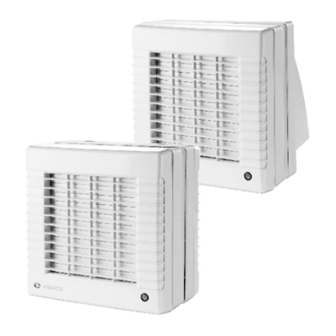
K TECH PRO Exklusiv 01 Technical manual

Axial duct domestic electric fans
Kleinraumventilator
Passport/
Operation instruction
Pass/
Bedienungsanleitung
EN
DE
EN
DE

EN
2
Attention!
This device is not intended for persons with limited physical or mental abilities (including children),
who have no experience or knowledge in using the device, are unsupervised or have not been trained by persons
responsible for their safety. Parents are responsible for their children.
Safety requirements
Ensure that all electric power is turned off before carrying out any work. The electrical connections must be carried out
by a qualified electrician and must comply with the relevant local regulations. The voltage and frequency of the power
supply must comply with the fan's specifications. The installation site must have an all-pole disconnecting device
with a contact opening width of at least 3 mm. The fans are double-insulated and do not require a protective
earth conductor. If operated near a fireplace with chimney, care must be taken to ensure that sufficient air can enter
the room being ventilated. In rooms with high humidity, installation must be done in accordance with DIN/VDE 0100
T701. Use a soft brush or damp cloth to clean, do not use any solvents. This appliance can be used by children
aged from 8 years and above and persons with reduced physical, sensory or mental capabilities or
lack of experience and knowledge if they have been given supervision or instruction concerning use of the appliance
in a safe way and understand the hazards involved. Children shall not play with the appliance.
Cleaning and user maintenance may not be carried out by children unsupervised.
Attention!
Appropriate use
This fan is designed to remove unpleasant smells and moisture from toilets and bathrooms,
as well as other small rooms.
Symbol legend of options
Legend Name
СAxial duct domestic removable electric fans with back flow valve.
-02 Axial duct domestic removable electric fans with the pull-chain switch of turning on/o of the power supply
or timer.
TURBO Domestic axial duct fan equipped with high capacity motor.
ET Axial duct domestic removable electric fans with electronic timer.
HT Axial duct domestic removable electric fans with humidity sensor.
ETF Axial duct domestic removable electric fans with phototimer.
MT Domestic axial duct fans with motion sensor
MR Electric axial duct domestic removable multioptional fans with 2 modes and built in Fusion Logic
1.0.controller.
MRH Electric axial channel household attachable multioption dual-mode fan with built-in Fusion Logic 1.1
controller.
EC Domestic axial duct fans with electric switch engine
Name of color Domestic axial duct fan designed in Ivory, Champagne, Gray metal, White carbon, Black carbon, Dark gray
metal, Chrome, Gold, Matt black, Obsidian colours
dditional options can be combined or absent.
Main technical characteristics
Characteristics
AURA 4
AURA 5
PARUS 4
PARUS 5
PARUS 4
TURBO
PARUS 5
TURBO
PARUS 4 EC
PARUS 5 EC
PRO 4
PRO 5
PRO 6
RIO 4
RIO 5
SILENT 4
SILENT 5
SILENT 4
TURBO
SILENT 5
TURBO
SLIM 4
SLIM 5
SLIM 6
STANDARD 4
STANDARD 5
Flange
diameter (mm) 100 125 98 123 98 123 98 123 100 125 160 98 123 100 125 100 125 100 125 150 100 125
Eciency
(m3/h) 90 180 90 165 110 205 75 135 115 195 320 100 180 90 180 120 225 90 140 250 100 185
Power
consumption
(W)
8,4 10 9 13 16 20 0,05 0,07 14 18 22 14 16 8,4 10 19 20 7,8 10 10 16 20
Noise level (dB) 25 30 25 30 36 39 25 27 32 34 36 32 33 25 30 36 38 25 30 33 35 36
Weight (kg) 0,5 0,7 0,53 0,7 0,53 0,7 0,6 0,75 0,55 0,65 0,95 0,5 0,65 0,5 0,7 0,5 0,7 0,55 0,65 0,77 0,7 0,75
C mains voltage 220-240 V, frequency 50 Hz.
• The fan should not be used outside the specified temperature range (+ 1 ° C to + 40 ° C).
• Read this manual and the contents carefully before using or operating the device.

EN
2
3
Моdel AURA / SILENT PARUS /RIO /PRO /STANDARD SLIM
Options
C, MT, MR,
TURBO,
No options
MRH, C
MRH
С, MR,
No options
-02, С-02, MR-
02, С MR-02,
MRH,
C MRH, MRH-
02, C MRH-02
IP 25 24 24 25 24
Main technical characteristics
Characteristics
Exklusiv 03 - Ø 100
Exklusiv 01 - Ø 125
Flange
diameter (mm) 100 125 98 123 98 123 98 123 100 125 160 98 123 100 125 100 125 100 125 150 100 125
Eciency
(m3/h) 90 180 90 165 110 205 75 135 115 195 320 100 180 90 180 120 225 90 140 250 100 185
Power
consumption
(W)
8,4 10 9 13 16 20 0,05 0,07 14 18 22 14 16 8,4 10 19 20 7,8 10 10 16 20
Noise level (dB) 25 30 25 30 36 39 25 27 32 34 36 32 33 25 30 36 38 25 30 33 35 36
Weight (kg) 0,5 0,7 0,53 0,7 0,53 0,7 0,6 0,75 0,55 0,65 0,95 0,5 0,65 0,5 0,7 0,5 0,7 0,55 0,65 0,77 0,7 0,75
The fans are designed for connection to AC mains voltage 220-240 V, frequency 50 Hz.
Exklusiv 02 Ø 100
Exklusiv 02 Ø 125
Exklusiv 01 - Ø 100
Exklusiv 03 - Ø 125

EN
4
Exklusiv 01 / Exklusiv 02
F* EC
Ød
X
A
Y
B
Model d A B X Y E F* С
100 155 155 135 135 70 7 24
125 175 175 155 155 78 8,5 24
Exklusiv 02 98 175 220 135 135 74 6 44
Exklusiv 02 123 190 237 160 160 79 6 52
98 170 170 135 135 74 6 38
123 200 200 160 160 79 6 38
Exklusiv 01 100 155 155 135 135 70 7 31
Exklusiv 01 125 175 175 155 155 78 8,5 32
100 160 160 140 140 76 7 9
125 180 180 160 160 82 8,5 9
150 205 205 187 187 86 10 9
100 180 250 160 230 58,5 7 24
125 180 250 160 230 58,5 8,5 24
*- This size is present only in fans with “back flow valve” option
Installation and set up procedures
The fan can be connected to ventilation ducts. The device is designed for wall and ceiling mounting. The fan is fastened with
screws. Permissible deviation in the vertical and horizontal position of the mounting surfaces to be installed: ± 0.5 mm.
S3
S1 Automatic circuit
breaker S2 external switch S3 Built-in disconnector
Exklusiv 03
B
A
F
D
C
Model A B C D E F
Exklusiv 03 122 138 119 103,6 94 139
Exklusiv 03 147 163 144 128,6 101 146
182 198 179 163,6 104 154
Pic.1 AURA
/SILENT
Pic.2 SLIM Pic.3 SLIM -02
(pull switch)

EN
4
5
Schematic diagrams of Ekxklusiv fan`s connection
Scheme 1 (for Exklusiv 01)
X- terminal block, 2 pairs
Scheme 2(for Exklusiv 02)
Activation of fans with option 02 (pull switch), X terminal
block, 2 pairs
S3
220-240V
220-240V
PRO
B
A
F
D
C
Model A B C D E F
PRO 4 122 138 119 103,6 94 139
PRO 5 147 163 144 128,6 101 146
PRO 6 182 198 179 163,6 104 154
Wiring diagram connection of Exklusiv fans to the network
Connection of fan to the network shown in pic. 1-4
• remove the decorative front panel
• hold the power wire through the cable hole 1 in the case
• strip the insulation on 5-7 mm from the wire end
• insert wires into terminal box X (X2) and press them by tap screw
• fix the wires by means of cable clamp 2
• combine clamps of the decorative panel with grooves in the case
• fix the panel with screw
Pic.1
Exklusiv 01
2
1

EN
6
Exklusiv 02
•remove the decorative front panel and terminal block cover
• hold the power wire through the cable hole 1 in the case
• strip the insulation on 5-7 mm from the wire end
• insert wires into terminal box X and press them by tap screw
• fix the wires by means of cable clamp 2
•install the cover of terminal block and front panel by easy pressure
Pic.2Exklusiv 02
Pic.8 PRO
Pic.
9 PRO
Exklusiv 03
• remove the terminal block cover;
• hold the power wire through the cable hole 1 in the case
• strip the insulation on 5-7 mm from the wire end insert wires into
terminal box X and press them by tap screw;
• fix the wires by means of cable clamp 2;
•install the cover of terminal block.
•Install brackets of holders;
•Install first couple of covers in brackets ;
•Install the fan ;
•Butt airvents from two sides to the fan case
•Fix the fan case with airvents by means of another couple of covers.
Pic.3Exklusiv 03
Pic.
4Exklusiv 03
1
2
cover
of terminal block
fun
duct
connection
duct
connection
cover
cover
bracket

EN
6
7
Maintenance
• Remove the fan impeller if it is very dirty.
• Wipe all plastic parts with a soft cloth dampened with a soap solution
Malfunction Probable cause Remedy
When connected to the
power grid, the fan does not
rotate, does not respond to
controls.
The mains supply is not connected.
It is necessary to consult a specialist.
Internal connection fault.
Low air flow. The ventilation system is clogged. Clean the ventilation system.
Increased noise or vibration.
The impeller is blocked. Clean the impeller.
The fan is not fixed or incorrectly mounted. Correct the installation error.
The ventilation system is clogged. Clean the ventilation system.
Possible problems and solutions
ATTENTION!
The fan and the service controlling equipment has to be isolated from power supply during the installation
time and service.
Pic.
4 STANDARD
Pic.
5 STANDARD-02
Storage and transportation
Keep the fan only in the packaging of the manufacturer in a ventilated room at a temperature of +5 ° C to +40 ° C and relative
humidity of 80% (at T = 25 ° C). Keeping time - 5 years from date of manufacture. Products transported by any transport
provided consumer protection or transport container from the direct effects of rainfall, lack of bias transport places during
transport, the lack of mutual physical impact during transportation and preservation of fans. Transportation is carried out in
force with the rules for this transport.
This marking indicates that this product should not be disposed with other household wastes throughout the EU. To
prevent possible harm to the environment or human health
from uncontrolled waste disposal, recycle it responsibly to
promote the sustainable reuse of material resources. To return
your used device, please use the return and collection
systems or contact the retailer where the product was purchased. They
can take this product for environmental safe recycling.
Disposal

EN
8
Warranty
The manufacturer guarantees normal operation for 5 years from the date of purchase in retail, subject to transport,
storage, installation, commissioning and other conditions and requirements of this manual have been complied with. If a
sales date is missing, the guarantee period begins on the date of issue.
If the fan fails during the warranty period due to manufacturer errors, the device will be repaired free of charge or replaced
if the serial number on the product and the product passport are identical.
The product badge must be on the fan! Make sure your product has this badge and leave it on the product for its entire life.
Please keep the purchase documents (invoice or receipt) that confirm the date and time of purchase of the product.
The goods are produced in accordance with:
TR CU 004/2011 - «About safety of low voltage equipment»;
TR CU 020/2011 - «Electromagnetic compatibility of technical devices
Manufacturer
K-TECH-PRO GmbH
Industriestraße 11
93455 Wilting
Fon: (0 99 71) 13 04 64 20
Fax: (0 99 71) 13 04 64 210
E-Mail: [email protected]
Internet: www.k-tech-pro.de
Register court: Amtsgericht Regensburg
Commercial register registration number: HRB 13355
VAT identification number according to § 27a Sales tax law:
DE286990027
WEEE-Reg.Nr.
47786558

DE
8
Zweckmäßige Verwendung
Dieser Ventilator ist zur Entfernung von unangenehmen Gerüchen und Feuchtigkeit aus Toiletten und Badezimmern,
sowie anderen kleinen Räumen.
HINWEIS!
Dieses Gerät ist nicht für Personen mit eingeschränkten körperlichen oder geistigen Fähigkeiten
(einschließlich Kinder), die keine Erfahrung oder Kenntnisse im Umgang mit dem Gerät haben,
unbeaufsichtigt sind oder nicht von Personen geschult wurden, die für ihre Sicherheit verantwortlich sind,
bestimmt. Eltern haften für Ihre Kinder.
SICHERHEITSANFORDERUNGEN
Alle Arbeiten im spannungslosen Zustand durchführen. Die elektrischen Anschlüsse dürfen nur durch
autorisiertes Fachpersonal und entsprechend den jeweils gültigen Vorschriften erfolgen. Spannung und
Frequenz der Stromversorgung müssen mit den Angaben des Ventilators übereinstimmen.
Installationsseitig ist eine allpolige Trennvorrichtung mit einer Kontaktöffnungsweite von mind. 3 mm
vorzusehen. Die Ventilatoren sind doppelt schutzisoliert und benötigen keinen Schutzleiter.
Bei Betrieb schornsteinabhängiger Feuerstellen im zu entlüftenden Raum muss für ausreichend Zuluft
gesorgt werden. Die Installationin Feuchträumen muss gemäß DIN/VDE 0100 T701 erfolgen. Zur Reinigung
Pinsel oder feuchtes Tuch verwenden, keine Lösungsmittel einsetzen.
HINWEIS!
•Der Ventilator sollte nicht außerhalb des angegebenen Temperaturbereichs (+ 1 ° C bis + 40 ° C)
verwendet werden.
•Lesen Sie dieses Handbuch und den Inhalt sorgfältig durch, bevor Sie das Gerät verwenden bzw. in
Betrieb nehmen.
9

DE
10
Technische Grunddaten
Eigenschaften
Exklusiv 01 - Ø 100
Exklusiv 01 - Ø 125
Durchmesser(mm)100 125 98 123 98 123 98 123 100 125 160 98 123 100 125 100 125 100 125 150 100 125
Förderleistung
(m³/h) 90 180 90 165 110 205 75 135 115 195 320 100 180 90 180 120 225 90 140 250 100 185
8,4 10 9 13 16 20 0,05 0,07 14 18 22 14 16 8,4 10 19 20 7,8 10 10 16 20
Geräuschpegel
(dB)25 30 25 30 36 39 25 27 32 34 36 32 33 25 30 36 38 25 30 33 35 36
Gewicht (kg)0,5 0,7 0,53 0,7 0,53 0,7 0,6 0,75 0,55 0,65 0,95 0,5 0,65 0,5 0,7 0,5 0,7 0,55 0,65 0,77 0,7 0,75
Die Lüfter sind für den Anschluss an ein Wechselstromnetz mit einer Spannung von 220-240 V und einer Frequenz von 50 Hz
ausgelegt.
Stromverbrauch
(kW)
Exklusiv 03- Ø 100
Exklusiv 03- Ø 125
Exklusiv 02- Ø 100
Exklusiv 02- Ø 125

DE
10
11
ОПЦИЯЛАРДЫҢ ШАРТТЫ БЕЛГІЛЕРІ
Белгіленуі Аталуы
СКері клапаны бар тұрмыстық белағаштық каналдық қапталған электр желдеткіштер
-02 Желдеткіш немесе таймерді қуат көзіне қосу/ қуат көзінен өшіру үшін тартулы бау
жабдықталған тұрмыстық белағаштық каналдық қапталған электр желдетк іштер
TURBO Өнімділігі жоғары қозғалтқышы бар тұрмыстық осьтік арналық электр желдеткіштері.
ET Электрондық таймері бар тұрмыстық белағаштық каналдық қапталған электр желдеткіштер
HT Ылғалдылық тетігімен жабдықталған тұрмыстық белағаштық каналдық қапталған электр желдеткіштер
ETF Фототаймері бар тұрмыстық белағаштық каналдық қапталған электр желдеткіштер
MT Қозғалыс датчигі бар тұрмыстық арналы өстік электр желдеткіштері.
MR Ішіне құрастырылған Fusion Logic 1.0. контроллері бар тұрмыстық белағаштық каналдық қапталған
мультиопциялық екі режимдік электр желдеткіштер
MRH Ішіне құрастырылған Fusion Logic 1.1. контроллері бар тұрмыстық белағаштық каналдық қапталған
мультиопциялық екі режимдік электр желдеткіштер
EC Электрмен комутацияланатын түрмыстық арналы өстік элеткр желдеткіштері.
Name of color
(түстің атауы)
Сәндік орындалудағы Ivory, Champagne, Gray metal, White carbon, Black carbon, Dark gray metal, Chrome,
Gold, Matt black, Obsidian түсті тұрмыстық арналы өстік электр желдеткіштері.
Қосымша опциялардың бір бірімен құрамдастырылған болуы немес жоқ болуы мүмкін.
Негізгі техникалық мәліметтері
Сипаттамалары
AURA 4
AURA 5
PARUS 4
PARUS 5
PARUS 4
TURBO
PARUS 5
TURBO
PARUS 4 EC
PARUS 5 EC
PRO 4
PRO 5
PRO 6
RIO 4
RIO 5
SILENT 4
SILENT 5
SILENT 4
TURBO
SILENT 5
TURBO
SLIM 4
SLIM 5
SLIM 6
STANDARD 4
STANDARD 5
Ернемек
диаметрi (мм) 100 125 98 123 98 123 98 123 100 125 160 98 123 100 125 100 125 100 125 150 100 125
Өнімділігі
(м3/час) 90 180 90 165 110 205 75 135 115 195 320 100 180 90 180 120 225 90 140 250 100 185
Тұтынатын қуаты
(Вт)
8,4 10 9 13 16 20 0,05 0,07 14 18 22 14 16 8,4 10 19 20 7,8 10 10 16 20
Шуыл деңгейі
(дБ) 25 30 25 30 36 39 25 27 32 34 36 32 33 25 30 36 38 25 30 33 35 36
Массасы (кг) 0,5 0,7 0,53 0,7 0,53 0,7 0,6 0,75 0,55 0,65 0,95 0,5 0,65 0,5 0,7 0,5 0,7 0,55 0,65 0,77 0,7 0,75
Желдеткіштер кернеуі 220-240 В, жиілігі 50 Гц болған ауыстырмалы электр тоқ жүйесіне қосу үшін мақсатталған.
Exklusiv 01 / Exklusiv 02
F E C
Ød
X
A
Y
B
Typ d A B X Y E F С
100 155 155 135 135 70 7 24
125 175 175 155 155 78 8,5 24
Exklusiv 02 98 175 220 135 135 74 6 44
Exklusiv 02 123 190 237 160 160 79 6 52
98 170 170 135 135 74 6 38
123 200 200 160 160 79 6 38
Exklusiv 01 100 155 155 135 135 70 7 31
Exklusiv 01 125 175 175 155 155 78 8,5 32
100 160 160 140 140 76 7 9
125 180 180 160 160 82 8,5 9
150 205 205 187 187 86 10 9
100 180 250 160 230 58,5 7 24
125 180 250 160 230 58,5 8,5 24
Vorbereitung für Montage und Inbetriebnahme
Der Lüfter kann an Lüftungsrohre angeschlossen werden. Das Gerät ist für die Wand- und Deckenmontage
konzipiert. Der Ventilator wird mit Schrauben befestigt. Zulässige Abweichung in vertikaler und horizontaler Lage der
zu installierenden Montageflächen: ± 0,5 mm.
Exklusiv 03
B
A
F
D
C
Typ A B C D E F
Exklusiv 03 122 138 119 103,6 94 139
Exklusiv 03 147 163 144 128,6 101 146
182 198 179 163,6 104 154
S3
S1 Sicherungsautomat S2 externer Schalter
Eingebauter S3-Trennschalter
(Zugschalter)

DE
12
Grundschemata zum Anschluss von Exklusiv-Lüftern
Schema 1 (Exklusiv 01)
X-Klemmenleiste, 2 Klemmen
Schema 2 (Exklusiv 02)
Aktivierung von Lüftern mit Option 02 (Zugschalter), X-
Klemmenleiste, 2 Paare
S3
220-240V
220-240V
Installationsabbildungen zum Anschließen der Lüfter der Exklusiv-Serie an das Netzwerk
Die Vorgehensweise zum Anschließen des Lüfters an das Stromnetz ist in den Abbildungen 1-4 dargestellt
Abbildung 1:
Exklusiv 01
2
1
4 ші сурет: STANDARD 5 ші сурет: STANDARD-02
•Entfernen Sie die Aussenabdeckung.
•Führen Sie das Netzkabel durch das Loch (1) zum Anschluss im Lüftergehäuse.
•Entfernen Sie 5-7 mm der Drahtisolierung.
•Führen Sie die Drähte in die Klemmenleiste X ein und befestigen Sie diese.
•Sichern Sie die Drähte mit der Klemme (2).

DE
12
13
Exklusiv 02
•Entfernen Sie die Aussenabdeckung.
•Führen Sie das Netzkabel durch das Loch (1) zum Anschluss im Lüftergehäuse.
•Entfernen Sie 5-7 mm der Drahtisolierung.
•Führen Sie die Drähte in die Klemmenleiste X ein und befestigen Sie diese.
•Sichern Sie die Drähte mit der Klemme (2).
Exklusiv 03
Abbildung 3
•Entfernen Sie die Aussenabdeckung.
•Führen Sie das Netzkabel durch das Loch (1) zum Anschluss im Lüftergehäuse.
•Entfernen Sie 5-7 mm der Drahtisolierung.
•Führen Sie die Drähte in die Klemmenleiste X ein und befestigen Sie diese.
•Sichern Sie die Drähte mit der Klemme (2).
Abbildung 4
•Montieren Sie die Sockelfüße.
•Führen Sie eine Abdeckungshälfte in den Sockelfuß ein.
•Installieren Sie den Lüfter.
•Verbinden Sie die Lüftungsrohre auf beiden Seiten mit dem Lüftergehäuse stoß auf
stoß.
•Befestigen Sie die obere Abdeckungshälfte, die Abdeckungen dichten
die Verbindung ab.
•Somit kann der Ventilator jederzeit ausgebaut werden.
Abbildung 2: Exklusiv 02
Abbildung 3: Exklusiv 03 Abbildung 4: Exklusiv 03
1
2
Abdeckung des
Klemmenblocks
Motor
Kanalanschluss
Kanalanschluss
Abdeckung
Abdeckung
Sockelfuß

DE
14
Wartung / Reinigung
•Entfernen Sie bei starker Verschmutzung das Lüfterlaufrad.
•Wischen Sie alle Kunststoffteile mit einem weichen, mit Seifenlösung angefeuchteten Tuch ab
Mögliche Probleme Mögliche Ursache
Bei Anschluss an das Stromnetz dreht
sich der Lüfter nicht und hat keinen
Einfluss auf die Steuerung.
Das Netzteil ist nicht angeschlossen. Es ist notwendig, einen
Spezialisten zu konsultieren.
Interner Verbindungsfehler.
Geringer Luftstrom. Das Lüftungssystem ist verschmutzt. Lüftungssystem reinigen.
Hohe Geräusche oder Vibrationen.
Rotor verschmutzt und unwuchtig. Reinigen Sie den Rotor.
Der Lüfter ist falsch angeschlossen
oder installiert.
Beseitigen Sie den
Installationsfehler.
Das Lüftungssystem ist verschmutzt. Lüftungssystem reinigen.
Mögliche Probleme und Möglichkeiten, sie zu beseitigen
ACHTUNG!
Ventilator vor der Montage und / oder Wartung von der Stromversorgung trennen.
Mögliche Lösung
Lagerbedingungen
Der Lüfter sollte nur in der Verpackung und Verpackung des Herstellers in einem belüfteten Raum mit einer Temperatur
von + 5 ° C bis + 40 ° C und einer relativen Luftfeuchtigkeit von nicht mehr als 80% (bei T = 25 ° C) gelagert werden.
Entsorgung
Innerhalb der EU weist dieses Symbol darauf hin, dass dieses Produkt nicht über den Hausmüll entsorgt
werden darf. Altgeräte enthalten wertvolle recyclingfähige Materialien, die einer Verwertung zugeführt
werden sollten und um der Umwelt bzw. der menschlichen Gesundheit nicht durch unkontrollierte
Müllbeseitigung zu schaden. Bitte entsorgen Sie Altgeräte deshalb über geeignete Sammelsysteme oder
senden Sie das Gerät zur Entsorgung an die Stelle, bei der Sie es gekauft haben. Diese wird dann das Gerät
der stofflichen Verwertung zuführen.

DE
14
15
Ақаулық Ықтимал себебі Жою тәсілі
Желіге қосылған кезде желдеткіш
айналмайды, басқару органдарына
әсер етпейді.
Қоректендіргіш желі қосылмаған.
Маманға жүгіну қажет.
Ішкі қосылудағы ақаулық.
Төмен ауа шығыны. Желдету жүйесі ластанған. Желдету жүйесін тазалаңыз.
Жоғары шу немесе діріл.
Қанатша ластанған. Қанатшаны тазалаңыз
Желдеткіш бекітілмеген немесе дұрыс
орнатылмаған.
Монтаждау қатесін жой-
ыңыз.
Желдету жүйесі ластанған. Желдету жүйесін тазалаңыз.
Сақтандыру!
Желдеткіш пен көмекші тексергіш құрылғысы құрастырып монтаждау ж
электр қуат көзінен ажыратылып қойылуы қажет.
Herstellergarantien
Der Hersteller garantiert 5 Jahre ab Kaufdatum im Einzelhandel den normalen Betrieb, vorbehaltlich Transport, Lagerung,
Installation, Inbetriebnahme und anderer Bedingungen und Anforderungen dieses Handbuchs wurden eingehalten.Fehlt
ein Verkaufsdatum, beginnt die Garantiezeit mit dem Ausstellungsdatum.
Wenn der Lüfter während der Garantiezeit aufgrund von Fehlern des Herstellers ausfällt, wird das Gerät kostenfrei repariert
oder ggf. ausgetauscht, wenn die Seriennummer auf dem Produkt und der Produktpass identisch sind.
Die Produktplakette muss sich auf dem Ventilator befinden! Stellen Sie sicher, dass Ihr Produkt über diese Plakette verfügt,
und lassen Sie sie während der gesamten Lebensdauer auf dem Produkt.
Bitte bewahren Sie die Kaufdokumente (Rechnung oder Quittung) auf, die das Datum und die Uhrzeit des Kaufs des
Produkts bestätigen.
Die Ware wird entsprechend hergestellt:
КО ТР 004/2011 - "For the safety of low-voltage devices";
КО ТР 020/2011 - "Electromagnetic compatibility of technical means".
Hersteller
K-TECH-PRO GmbH
Industriestraße 11
93455 Wilting
Fon: (0 99 71) 13 04 64 20
Fax: (0 99 71) 13 04 64 210
E-Mail: [email protected]
Internet: www.k-tech-pro.de
Registergericht: Amtsgericht Regensburg
Handelsregister Registernummer: HRB 13355
Umsatzsteuer-Identifikationsnummer gemäß § 27a Umsatzsteuergesetz:
DE286990027
WEEE-Reg.Nr.
47786558

EN DE
K-TECH-PRO GmbH reserves the right to make changes without notification.
Sold/ Name of company, shop stamp/
Serial number: __________________________
Sale date/ : ____________________________
Date manufacture/
________________________
Mark of Quality Department/ :
_____________________________
Approval certificate/
The fan is recognized suitable for operation/
Exklusiv 01
Ø 100
Exklusiv 01
Ø 125
No options
С
-02
TURBO
ET
HT
ETF
MT
MR
MRH
EC
Ivory
Gray Metal
Dark Gray Metal
Champagne
White Design
Black Design
White Carbon
Black Carbon
Black Al
Chrome
Gold
Obsidian
Matt Black
Type
Оption
Name of color
Exklusiv 02
Ø 100
Exklusiv 02
Ø 125
Exklusiv 03
Ø 100
Exklusiv 03
Ø 125
This manual suits for next models
2
Table of contents
Languages:
Other K TECH PRO Fan manuals
Popular Fan manuals by other brands

Exodraft
Exodraft RS009-4-1 owner's manual

Pichler
Pichler LG 750 Operating and installation instructions

COOK
COOK TMX Installation, operation and maintenance manual

RadonAway
RadonAway SF180 installation instructions

Caframo
Caframo 810CA-BBX operating instructions

Siegenia
Siegenia AEROVITAL Original operating instructions

Manrose
Manrose MRUF150WH Installation and wiring instructions

Panasonic
Panasonic F-60TAN Operating and installation instructions

Honeywell Home
Honeywell Home DR65A3000 Professional installation guide

Matsui
Matsui MTF3613RE instruction manual

Aereco
Aereco VPH2 installation instructions

ClimateMaster
ClimateMaster DB Series installation instructions