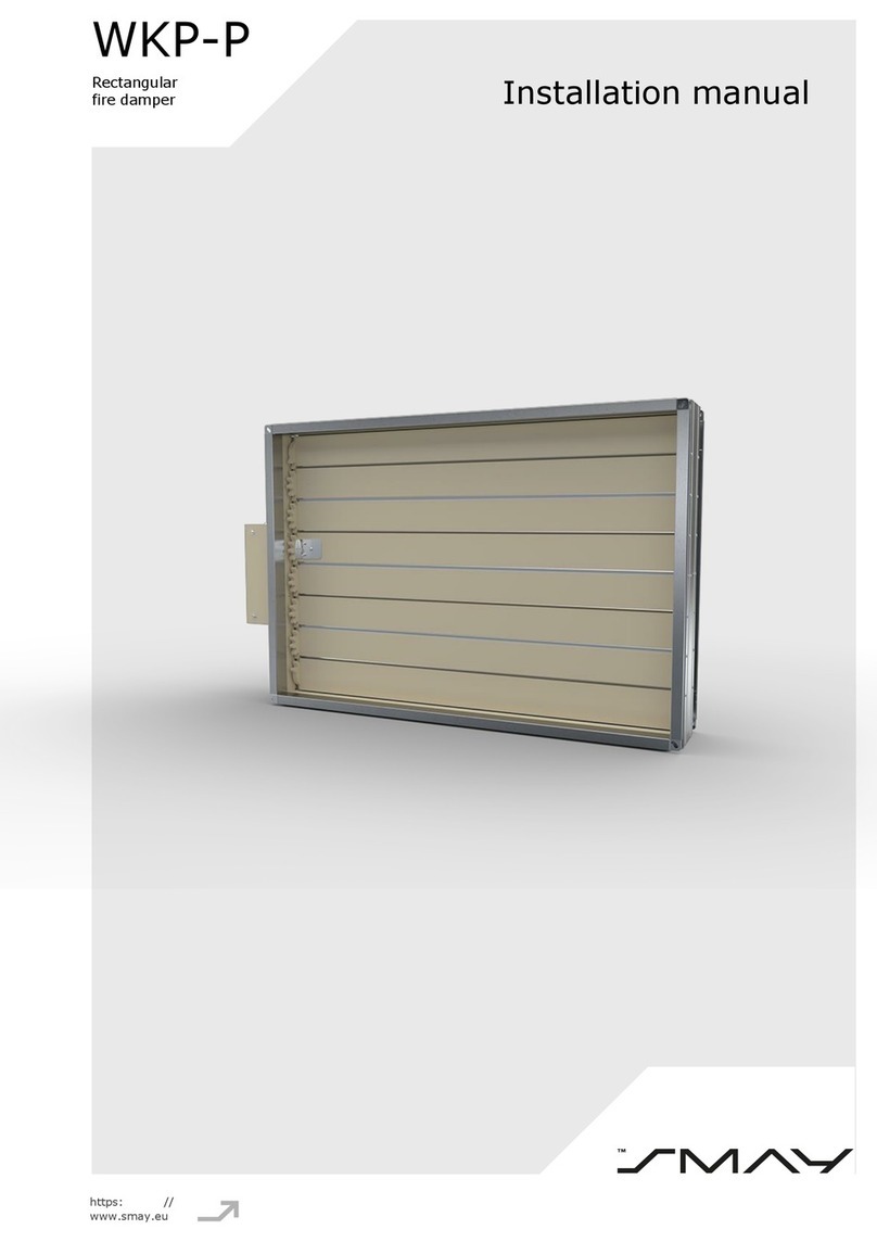
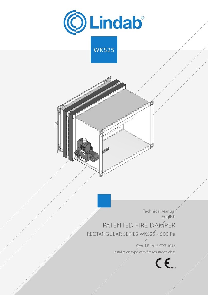
K-VENTIL FD-10 User manual

FIRE DAMPERS / SHUTTERTYPE
K-VENTIL ventilation equipment
export@kventil.com | +356 79667970 | www.kventil.com
FD/DFD-10 DESIGN & CONSTRUCTION FEATURES
Description
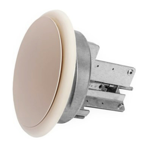
Model FD/DFD-10 is a fire damper approved for installation in walls with a fire resistance
rating of less than 3 hours. This damper installed vertically in HVAC systems that
automatically shut down in the event of fire.
Construction
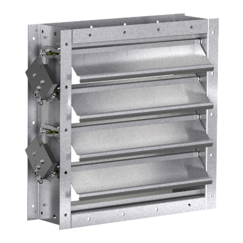
Frame : Roll formed, galvanized steel
Blades : Low profile roll formed, galvanized steel
Features
Stainless steel closure springs
Fusible links [165ºF (74ºC) standard]
Vertical Mount
Dynamic Curtain Fire Damper Static Curtain Fire Damper
Optional Features
Sealed transitions and sleeves
One piece retaining angle (POC)
Transitions (A,B,C & CR )

FIRE DAMPERS / SHUTTERTYPE
K-VENTIL ventilation equipment
export@kventil.com | +356 79667970 | www.kventil.com
Factory Sleeven Option
Fire dampers are available in factory fornisted sleeven. Sleevens are galvanized steel and are
available in 1,0mm –1,5mm thicknesses and lengths up to 914mm. “C” dimension specifies
location of damper within the sleeven. Minimum is 102mm; Maximum is “L” less 102mm,
which allows for mounting angle installation and duct connection at each end of sleeve. If
“C” dimension is not specified, it will be provided as one half of “L” dimension (damper
centered in sleeve).

FIRE DAMPERS / SHUTTERTYPE
K-VENTIL ventilation equipment
export@kventil.com | +356 79667970 | www.kventil.com
FD/DFD-10 OPTIONS AND ACCESSORIES INSTALLATION
Gauges and Lengths of Fire Damper Sleeve
All fire Dampres must be installed in a steel sleeve of the required gauge and length. See
table below for required minimum sleeve gauges. Maximum sleeve thickness is 10 gauge
(3,5mm). Sleeve inside dimensions must equal damper out side dimensions. Sleeves shall
extend a maximum of 6in. (152mm) beyond the wall opening on each side (see Figure 1)
Attaching Fire Dampers to Sleeves
Fire dampers must be attached to sleeves as shown in Figure 2. Al four sides of the damper
frame must be attached to the sleeve with one row of attachments on each side the blade
channel.Attachments must be spaced a maximum of 4 in.(102mm) on centers and a

FIRE DAMPERS / SHUTTERTYPE
K-VENTIL ventilation equipment
export@kventil.com | +356 79667970 | www.kventil.com
maximum of 1 in.(25mm) from corners.A minumum of 4 attachments (2 on each side of the
blade channel) pers ide (16 per damper) are required.
One of the methods of attachment shown below must be used.
-
tack or spot welds ( sleeves thicker than 16 Ga shall not be provided with spot
welds ).
-
10 sheet metal screws
-
1/4 in. (6mm) bolts and nuts
-
3/16 in. (4.7mm) steel pop rivets
Securing Fire Damper and Sleeves to Wall Openings
The fire damper must be installed such that the centerline of the blades are mounted in the
plane of the wall.Fire damper and sleeve assemblies must be installed in wall openings using
retaining angles on each side of the wall as described below:
-
Retaining angles for 1½ hour rated dampers with a height 36 in.(914mm) or less must
be a minumum of 16 ga. (1.5mm).The leg of the retaining angle on the damper sleeve
shall be a minumum of 2 in. (51mm).The leg of the retaining angle on the wall shall
be long enough to cover the annular space and overlap the wall by a minumum of 1

FIRE DAMPERS / SHUTTERTYPE
K-VENTIL ventilation equipment
export@kventil.com | +356 79667970 | www.kventil.com
in. (25mm).(See Figure 3).Retaining angle legs may be reversed with leg of retaining
angle with annular space of opening so angle and sleeve flush against barrier.
-
Retaining angles shall not be attached to the sleeve with a tack, spolt weld or
rivets.3/4x10 screws and 1x10 bolts and nuts.The corners shall be attached attached
at the corners with one rivet.
-
Retaining angles should not be fastened to the wall material. The angles should only
sandwich the wall and allow for damper/sleeve expansion during periods of instense
heat.
Connecting Ducts to Fire Damper Sleeves
Any duct connection other than breakaway is considered rigid. The connections shown are
considered breakaway. Factory furnished duct collars on type R and CR fire dampers are also
considered breakaway.
Duct –Sleeve Connections
Traditional Breakaway Style Transverse Joints Transverse joints illustrated have always been
approved as breakaway connections. SMACNA testing has also approved the following
variations as breakaway connections. Breakaway connections shall have no more than two
#10 (4.8mm diameter) sheet metal screws on each side and on the bottom located in the
center of the slip pocket and shall penetrate both sides of the slip pocket (applicable to the
Plain “S” Slip and Hemmed “S” Joint).Transverse joint can be applied as top and bottom
joints with Drive Slip –side joints in duct heights up to 20 in. (508mm)

FIRE DAMPERS / SHUTTERTYPE
K-VENTIL ventilation equipment
export@kventil.com | +356 79667970 | www.kventil.com
ORDER PARAMETERS:
FD-10
F00
01
L1200
N 1000X700
FD-10: Static Fire Damper,
74'C Fusible links
N: Neck Size
DFD-10: Dynamic Fire
Damper, 74'C Fusible links
D: Neck Diameter
L: Requested Product Length
F00: No Flange
00: Standard Duct Connection
F30: Flange Width = 30mm
01: Through Wall Connection
F35: Flange Width = 35mm
This manual suits for next models
1
Table of contents