actionair Smoke/Shield PTC User manual

August 2004 PTC Dampers
Actionair
Installation and Operating Instructions
Smoke/Shield PTC, Vent/Shield PTC,
Hot/Shield PTC, Smoke/Shield PTC, and
Hot/Shield Vent PTC are all trademarks
of Actionair.
Smoke/Shield PTC
Modes 5 and 6 shown.
Hot/Shield PTC
Modes 5 and 6 shown.
Index
Heath and Safety.
General Information.
PTC Damper Installation. 2
Smoke/Shield PTC
Mode 1 Installation. 3
Smoke/Shield PTC and
Vent/Shield PTC
Modes 5 and 6 Installation. 3
Smoke/Shield PTC and
Vent/Shield PTC Control
Modes Dimensional Data. 4
Smoke/Shield PTC and
Vent/Shield PTC
Application and Wiring. 5
Hot/Shield PTC and
Hot/Shield Vent PTC
Damper Installation and
Dimensional Data.
Application and Wiring. 6
Hot/Shield PTC and
Hot/Shield Vent PTC
Dimensional Data. 7
Hot/Shield PTC and
Hot/Shield Vent PTC
Multiple Assembles 7
Smoke/Shield PTC,
Vent/Shield PTC,
Hot/Shield PTC and
Hot/Shield Vent PTC
Troubleshooting. 8
(Smoke/Shield PTC™ Modes 1,5 & 6
fail-safe spring close with manual or
electrical reset).
(Vent/Shield PTC™ Modes 5 & 6 fail-
safe spring open with manual or
electrical reset).
(Hot/Shield PTC™ Modes 5 & 6 are
operational up to 300 °C for 1 hour
with fail-safe spring closure).
(Hot/Shield Vent PTC™ are
operational up to 300 °C for 1 hour
with fail-safe spring opening).
Smoke/Shield PTC, Vent/Shield PTC,
Hot/Shield PTC, and Hot/Shield Vent PTC

2
All wiring should be carried out in
accordance with the wiring details
provided, the IEE and BS regulations,
by a competent person.
Care must be taken when installing
and inspecting dampers, as they may
close without warning due to a variety
of reasons. Particularly this may be in
the case of loss of electrical power, or
fire signal to temperature rise in the
ductwork. This is their prime function.
Do not introduce any items, fingers or
limbs between the blades.
Prior to handling, check the weight of
the unit and adopt suitable handling
techniques.
PTC Dampers
Health and
Safety
The PTC™range of dampers are
suitable for both horizontal and
vertical applications, for airflow in
either direction.
PTC™dampers to their maximum
width and height dimensions can be
used where the operating total
system pressure is up to 1500 Pa
and duct velocities to 15m/second.
All Smoke/Fire dampers are life safety
products and should be treated with
care during handling, storage and
installation.
PTC™dampers are designed for
applications in normal dry filtered air
systems and should be subject to a
planned inspection programme,
cleaning and light oil lubrication in
accordance with good industry
practice. When exposed to fresh air
intakes and/or inclement conditions
this may need to be performed more
regularly based on experience gained
from previous inspections.
Specialist or aggressive environments
may be unsuitable for this type of
damper. This should have been
checked with the Customer Service
department at the time of order. If
there are concerns this should be
addressed before installation.
For assistance with applications other
than those described please contact
our Customer Service Office.
Please note all installations must be
carried out in accordance with the
approval of the relevant local
authority.
General Information
All installations must be made in
accordance with approval of the
relevant local authority and if
HEVAC/HVCA frames have been
supplied, also in accordance with
HEVAC specification HVC 6/5/83,
extracts of which are given below.
Installation frames are delivered to
site as a complete assembly with the
appropriate PTC™damper fitted
therein.
The damper shall be installed
centrally in the thickness of a
brickwork or concrete surrounding
wall or floor, or in the case of thick
walls or floors, so that the centre line
of the frame is at least 50mm, but
not more than 75mm, away from the
nearest face of the wall or floor, in
which the assembly is mounted.
Care must be taken not to backfill
past the line marked on the label
on the shroud. If this does occur
it will inhibit the fitting and
removal of the interface.
(See diagram on the right).
The four tabs (building ties) forming
each fixing point shall provide a
positive fixing into the structure.
In brickwork or blockwork walls the
tabs shall be bent out and solidly
built into the mortar joints between
the brickwork or blockwork.
In the cases of reinforced concrete
walls or floors, the tabs shall be bent
out and tied with wire to the
reinforcing bars, which will be
deliberately left protruding into the
opening.
The gap between the installation
frame and builders work shall be
backfilled with mortar or concrete on
both sides of the flange.
Adjacent frame assemblies must be
separated by builder’s work of a
minimum thickness of 225mm
(between installation frame upstand
flanges unless approval has been
previously obtained from the
appropriate Authority).
In no case shall the HEVAC/HVCA
frame and damper assembly be
held in position merely by the
adjacent ductwork, and it should be
noted that in reinforced concrete
structures (especially floors), it will
not be sufficient to only backfill
between the damper installation
frame and surrounding opening
with mortar or fine aggregate
concrete mix without provision for
tying in the frame to the
surrounding reinforced concrete
structure.
When fitting the ductwork care
must be taken to ensure that the
ductwork is independently
supported and not relying on the
damper as a structural anchor, all
in accordance with Ductwork
Specification DW144. Access
doors should also be fitted as
required by DW144.
For Hot/Shield PTC and
Hot/Shield Vent PTC dampers
fitted to thickened fire rated
ductwork, please refer to notes
on page 7.
Damper Installation
Backfill
Limit Line
on Label
Damper Drive Shroud

3
Smoke/Shield PTC™
Mode 1 Installation Procedure
315 ±20mm
40 ±*75mm
5mm
130mm
135mm
108
130mm
TOP
*This dimension will vary on circular damper. Select
dimension to give smoothest radius on bowden cable.
1. Prepare ductwork
Prepare ductwork for Mechanical
fusible link as detailed below. (For
ductless installations, a suitable sized
plate or bracket must be fitted to the
installation, to allow the fusible link
fixing details to be achieved).
●Within the Mode 1 kit of parts, is a
self adhesive fusible link drilling
template label.
●This template should be positioned
on the duct in accordance with
the dimensions shown above.
●Using a 3.0mm dia bit, drill 2 fixing
holes.
●Using a 25mm dia hole cutter, drill
the central hole.
●Remove sharp edges.
248
28
56
84 260
100
112
12
108
70 25
130
108
130
Smoke/Shield PTC™Control Modes
are located outside of the ductwork
for ease of access and installation.
Control Modes 5 and 6 can be fitted
in any one of three orientations i.e.
Vertically down (Position 1)
Horizontally (Position 2), or
Vertically up (Position 3).
This can be simply and easily carried
out on site, by repositioning the
Location Plate and Control Mode on
to the snaplock™Drive Interface.
This flexibility ensures that the
damper and control mode require the
minimal amount of room.
Mode 1 (Smoke/Shield only) Modes 5 and 6 Three position 180°(Pivotable Control Mode)
Control Mode Dimensional Data
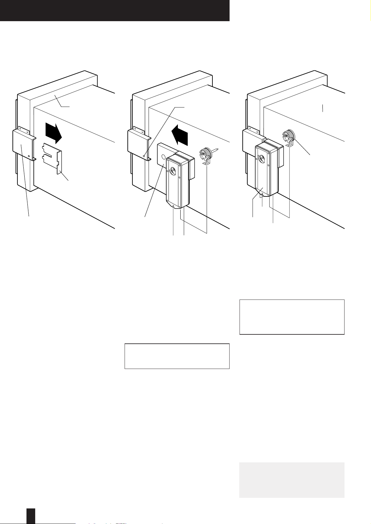
2. Fit Control Mode
●Remove transit plate from damper
shroud, and discard.
●Slide the interface and mode
assembly into the shroud, having
ensured that the slots in the
interface case and the drive
coupling are in line.
●Push the assembly fully home until
the spring retaining pin engages
through the location hole in the
shroud (snaplock™).
●(The mode 1 option, unlike the
mode 5/6, does not have the
facility of alternative actuator fixing
positions).
3. Fit Mechanical Fusible Link
●Locate the fusible link assembly in
the prepared hole in duct.
●Using the 2 self tapping screws
provided, secure the assembly.
4. Electrical Connections
●Where use is to be made of the
integral microswitch for indication
purposes, this should be wired as
described in the section
‘Application and wiring’.
5. Reset and Test Unit
●If the mechanical fusible link is
not fitted to the ductwork, it will
not be possible to reset the
unit. – This is a safety feature.
●Using a 14mm A/F spanner, rotate
the input shaft clockwise to reset
the damper.
●NOTE: After resetting, never leave
the spanner attached to the reset
shaft.
●Test unit by simply unscrewing
wing nut of the fusible link
assembly. This will result in the
damper releasing. Check for
damper closure.
FUSIBLE LINK
●Re-tighten the wing nut.
●Using a 14mm A/F spanner, rotate
the input shaft clockwise to reset
the damper.
●Remove spanner.
Note: It will not be possible to reset
the control mode if the fusible link is
not correctly installed.
Control
Mode 5/6
Ductwork
Electrical
Thermal
Release (ETR)
4
Smoke/Shield PTC™Vent/Shield PTC™
Remove transit plate and discard.
Slide the interface and mode
assembly into the shroud, having
ensured that the slots in the interface
case and the drive coupling are in
line.
Push the assembly fully home until
the sprung retaining pin engages
through the location hole in the
shroud (snaplock™). If due to space
restrictions, it is necessary to rotate
the mode through 90°to alternative
position see page 3, this may be
achieved by doing the following:
●Remove the screw (8mm A/F)
through the position indicator on
the mode. Retain the screw and
washer.
●Remove the mode and location
plate.
●Taking care not to disturb the
drive hexagon, replace the location
plate in the new orientation.
●Replace the mode in the new
orientation.
●Replace the washer and screw
tight.
Select a suitable position for the
Electrical Thermal Release (ETR) to
be mounted through the ductwork.
Ideally this should be in the top half
of the duct and/or above the interface.
Apply the self-adhesive template and
drill the necessary holes.
Push the ETR through the duct and
ensure that both screws are used to
hold it into position. Both screws
should be tightened fully to ensure
that both sections of the ETR are
closed up together. This is a safety
feature and should both sections not
be closed the unit will not operate.
If the ETR is not fitted to the
ductwork, the unit will not
operate.
For ductless installations the ETR
should be fitted onto the damper
spigot (not casing) above the damper
shroud, and in accordance with
these fitting instructions.
The damper should be manually
reset and released, using the winder
provided, to ensure that correct
mechanical operation is achievable.
It is possible to mechanically lock
open the Smoke/Shield PTC damper
to allow air to pass through it by
using the winder provided. This may
be necessary if electrical power is not
available. However the ETR is not
operable in this instance and the
damper will not release automatically
should the temperature rise or a fire
occur.
The unit must be wired as described
in Section Application and Wiring
details.
When power is available the unit
must be checked for correct
electrical operation. Power on to
reset, power off to release.
The unit must also be checked by
pushing, and holding, the test switch
on the ETR to confirm that the
damper releases. When pressure is
removed from the switch the damper
will reset. This may also be done
after the initial installation test, to
provide periodic operation of the
damper to simulate actual fail-safe
release under smoke/fire conditions.
The cable connecting the mode and
the ETR must not be shortened and
care should be taken not to damage
it. Shortening and/or damaging the
cable will render the unit inoperable.
This is due to a built in safety feature.
Vent/Shield PTC™dampers and
associated control modes 5 and 6
are reverse acting with spring action
opening.
Mode 5 and 6 Installation Procedure
Snaplock™
Drive Interface
Snaplock™
Retaining Pin
Locating Hole
Transit Plate
Damper Drive
Shroud
Smoke/Vent/
Shield PTC™
Damper
BLACK
GREEN/
YELLOW
BROWN
BLUE
ELECTRICAL THERMAL RELEASE
(SPRING BIASED TEST SWITCH)
ELECTRICAL THERMAL RELEASE
(SPRING BIASED TEST SWITCH)
TF 72 °C
TF 72 °C
2
1
S2
S3
S4
S5
S6
S1
N
E
M
L
VOLT FREE CONTACT
CHANGES OVER WHEN
DAMPER RELEASED
RATED 24V 3A
VOLT FREE CONTACT
CHANGES OVER WHEN
DAMPER RESET
RATED 24V 3A
SUPPLY
24V A.C. OR D.C.
TYPICALLY 7W (MOTORING) 2W (RESET)
COMMON
NORMALLY CLOSED
NORMALLY OPEN
NORMALLY CLOSED
NORMALLY OPEN
COMMON
VOLT FREE CONTACT
CHANGES OVER WHEN
DAMPER RESET
RATED 240V 2A
COMMON
NORMALLY CLOSED
NORMALLY OPEN
2
1
S2
S3
S4
S5
S6
S1
N
M
L
VOLT FREE CONTACT
CHANGES OVER WHEN
DAMPER RELEASED
RATED 240V 3A
VOLT FREE CONTACT
CHANGES OVER WHEN
DAMPER RESET
RATED 240V 3A
SUPPLY
220 - 240V A.C. 50/60Hz
TYPICALLY 8W (MOTORING) 3W (RESET)
COMMON
NORMALLY CLOSED
NORMALLY OPEN
NORMALLY CLOSED
NORMALLY OPEN
COMMON
5
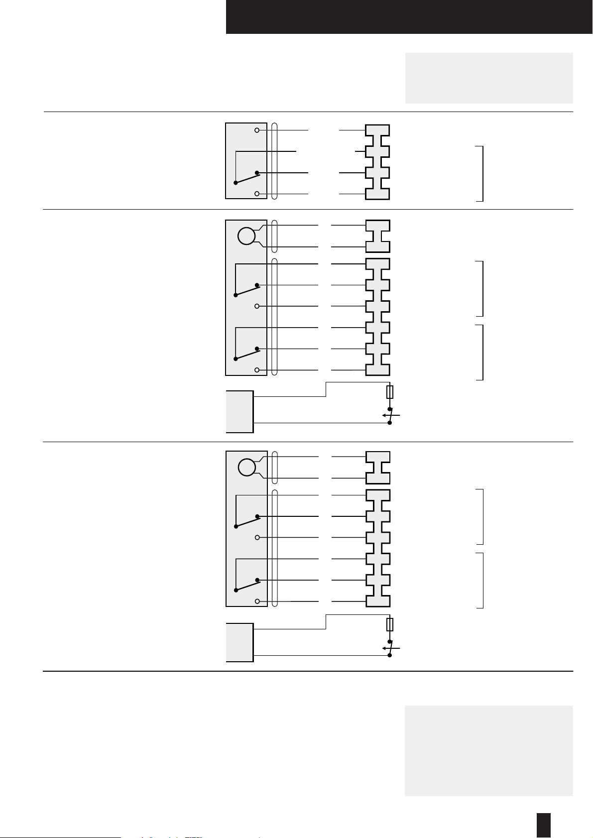
Smoke/Shield PTC™Vent/Shield PTC™
Smoke/Shield PTC
Application and
Wiring
Mode 1 (Manual System)
Manual opening.
Spring instant closure via mechanical
fusible link.
(Smoke/Shield version only, Vent/Shield not available.)
Mode 5 (24V System)
Power On –Damper motors open.
Power Off –Spring closure or via
Electrical Thermal Release.
External mechanical position indicator
with pointer.
Release Time ≈16 secs.
Reset Time ≈ 140 secs.
(Connect 24V via a safety isolating transformer.)
Vent/Shield PTC™dampers and
associated control modes 5 and 6
are reverse acting with spring action
opening.
Mode 6 (230V System)
Power On –Damper motors open.
Power Off –Spring closure or via
Electrical Thermal Release.
External mechanical position indicator
with pointer.
Release Time ≈16 secs.
Reset Time ≈ 1c secs.
(To isolate from main power supply, the system must
incorporate a device which disconnects the phase
conductors, with a least 3mm contact gap.)
General
One metre of halogen free low smoke
and fume electric cable is also
included with each control mode for
convenience of on site wiring. This
also provides the distinct safety
advantage of all electrics terminating
outside the duct, eliminating potential
in-duct fire hazards from wiring faults.
The Electrical Thermal Release is pre-
wired with 0.5m halogen free low
smoke and fume cabling to Control
Modes 5 and 6.
A Manual test switch fitted on the
ETR allows periodic operation of
damper simulating actual fail-safe
release under smoke/fire conditions.
Smoke/Shield and Vent/Shield
PTC™Dampers and associated
Control Modes 5 and 6 are
available without the ETR where
thermal operation is not required.
If integrating this unit with an Actionpac
damper control system (LNS or EM)
please refer to the relevant catalogue
and specific project details.
For non ETR applications refer to
specific product label on Mode, prior
to electrical connections.

BLUE N
L1
BROWN
1
2
3
4
VOLT FREE CONTACT
CLOSED WHEN
DAMPER RELEASED
VOLT FREE CONTACT
CLOSED WHEN
DAMPER RESET
SUPPLY
230V A.C 50/60 Hz
A.C. 230V
50 / 60 Hz
12.5 V A
8 / 3 W
–30...+50 °C
CONTINUOUS
A.C.
250V
6(3)A
M
6
Hot/Shield PTC™Hot/Shield Vent PTC™
Damper
Drive Shroud
Snaplock™
Retaining Pin
Transit
Plate
Ductwork Hot/Shield,
Hot/Shield Vent
Damper
Control Mode 5/6
housed in thermally
insulated enclosure
Dimensional Data
Install the Hot/Shield PTC™Damper
(complete with factory fitted damper
shroud and transit plate) into the
structure, connect and fit ductwork to
damper spigots. Remove transit plate
and discard. Slide the snaplock™
drive interface into the damper drive
shroud, snaplock™into position.
(See page 2.)
(Care must be taken when back filling
to ensure that the snaplock™
retaining pin location hole and the
entry slot of the damper drive shroud
is clear of builders work debris).
The above dimensional data is for
guide/general arrangement purposes.
Please contact our Customer
Service Office for details when
incorporating thickened fire rated
ductwork.
411
421
161
27
191
Damper Installation and Control
Mode Fitting
Series 2501
Hot/Shield PTC Application and Wiring
–
+
1
2
1
2
3
4
VOLT FREE CONTACT
CLOSED WHEN
DAMPER RELEASED
VOLT FREE CONTACT
CLOSED WHEN
DAMPER RESET
A.C./D.C.24V
50 / 60 Hz
10 V A
7/2 W
–30...+50 °C
CONTINUOUS
A.C.
250V
6(3)A
SUPPLY
24V A.C. or D.C.
M
Mode HM5 (24V System)
Power On –Damper motors open.
Power Off –Spring closure.
Cable specification:
Si HF Low Smoke and Fume,
Halogen Free, to IEC 754-1.
Conforming to 73/23/EEC directive.
Release Time ≈16 secs.
Reset Time ≈ 140 secs.
(Connect 24V via a safety isolating transformer.)
Mode HM6 (230V System)
Power On –Damper motors open.
Power Off –Spring closure.
Cable specification:
Si HF Low Smoke and Fume,
Halogen Free, to IEC 754-1.
Conforming to 73/23/EEC directive.
Release Time ≈16 secs.
Reset Time ≈ 140 secs.
(To isolate from main power supply, the system
must incorporate a device which disconnects the
phase conductors, with a least 3mm contact gap.)
Hot/Shield Vent PTC™Dampers and
associated Control Modes are reverse
action with spring operation

7
Hot/Shield PTC™Hot/Shield Vent PTC™
Dimensional Data
The following data is relevant to
square/rectangular dampers Series 2501
and 3501 when incorporating;
STD Standard 1.2mm (approx) sheet
steel ductwork.
THK Thickened fire rated ductwork up to
15mm thick.
(For dimensional data outside of these
parameters, refer to Customer Service
Office).
1. Transformation sections only required
when duct widths and/or heights is less
than 200mm, or if THK thickened fire
rated ductwork is greater than 15mm.
2. The following dampers with duct
widths and/or heights as listed will be
complete with transformation sections:
Duct widths and/or heights between
100mm –175mm, will have nominal
damper size of 200mm. Duct widths
and/or heights between 176mm –200mm,
please refer to Customer Service Office.
3. Dampers with duct widths and/or
heights of between 200mm –1000mm
are supplied as nominal damper sizes and
without transformation sections.
4. Always refer to Customer Service
Office for dimensional data when
incorporation THK thickened fire
rated ductwork, especially when
thicker than 16mm.
The following data is relevant to circular
dampers Series 2601 and 3601 when
incorporating;
STD (Standard 1.2mm (approx) sheet
steel ductwork).
THK (Thickened fire rated ductwork up to
35mm thick) (for dimensional data outside
of these parameters, refer to Customer
Service Office).
5. Transformation sections are always
included.
6. Dampers with duct diameters between
100mm diameter –150mm diameter, will
have nominal damper size of 200mm
diameter. Dampers with duct diameters
between 151mm diameter –982mm
diameter, will have nominal damper size
+50mm. Dampers with a nominal damper
size between 983mm diameter –
1000mm diameter, please refer to
Customer Service Office.
7. Always refer to Customer Service
Office for dimensional data when
incorporation THK thickened fire
rated ductwork, especially when
thicker than 35mm.
100 - 1000
DUCT WIDTH25
25
5025 * DUCT HEIGHT
3838 38
78
90
8357
Series 2501
Hot/Shield PTC™
Series 3501
Hot/Shield Vent PTC™
TRANSFORMATION
SECTION
SQUARE OR
RECTANGULAR
SQUARE OR
RECTANGULAR
100 - 1000
OVERALL WIDTH
OF INSTALLATION
FRAME IS DUCT
WIDTH + 114MM
* DUCT HEIGHT
DAMPER SPIGOTS 5MM
UNDER DUCT SIZE
100 - 1000
DUCT DIAMETER50 50
7550 DUCT DIAMETER
CIRCULAR
90
108
82
Series 2601
Hot/Shield PTC™
Series 3601
Hot/Shield
Vent PTC™
DAMPER CIRCULAR
SPIGOTS 3MM UNDER
DUCT SIZE
100 - 1000
2525
65383865 78
2525 CIRCULAR
OVERALL WIDTH
OF INSTALLATION
FRAME IS DUCT
DIA + 164MM
Series 2501 and 3501 Basic Damper (square/rectangular)
Series 2601 and 3601 Basic Damper (circular)
Multiple Assemblies
as provision for thermal expansion
(4mm/metre) should be allowed for
on multiple assemblies.
When fitted to fire rated
ductwork, please refer to
customer service office. Multiple
assemblies require installation
approval by the relevant local
authority.
Square and rectangular casings are
available in multiple module
arrangements, supplied complete
with blanking strips for site assembly
by others. Additional support as well
Interface Mode Assembly does
not fit into the shroud on the
damper.
SSM1, SSM5, SSM6, HSM5 & HSM6
•Check mode is in released position.
VSM5, VSM6, HSVM5 & HSVM6
•Check mode is in reset position.
•Check damper drive shaft is in line
to shroud, adjustment is made by
manually setting blades to fully
closed.
•The slots on the non-access side
of the shroud may be blocked (due
to removal of transit plate prior to
backfilling) - ensure adequate
clearance.
•Check alignment of drive coupling
slot in interface. If out of line, the
mode output drive is out of
synchronisation with the interface
drive. The mode will require to be
removed, and the refitted correctly
as follows:
SSM5, SSM6, HSM5 & HSM6
Remove mode. (Ensure released.)
Align interface coupling with slot on
interface. Refit mode with product
label uppermost. (Including location
plate and washer.)
VSM5, VSM6, HSVM5, & HSVM6
Remove mode. (Ensure reset.)
Align interface coupling with slot on
interface. Refit mode with product
label uppermost.(Including location
plate and washer.)
Produced by Graphic Partnership www.graphicpartnership.com
PTC Dampers
Troubleshooting
Below is a quick guide to problems that may be encountered. For detailed
actions, reference to the main document is necessary.
Please note modifications made to units will invalidate warranties etc.
Product Commissioning
and Maintenance
Available.
Control Mode (5 and 6) does
not operate electrically.
•The ETL is not correctly fitted to duct.
•The mode is incorrectly wired.
•The ETL cables have been
damaged or tampered with.
Control Mode operates, but
limited, or no movement of
damper blades is observed.
•The mode is not correctly
synchronised with the interface
•The damper is damaged or poorly
installed.
•The retaining pin in the interface is
not protruding through the location
hole in the shroud.
•Foreign matter is impeding blade
movement.
•Location plate omitted.
•Mode not screwed down correctly.
Interface assembly cannot be
removed.
•Mode is at incorrect position.
SSM5, SSM6, HSM5, HSM6 -
release position permits removal.
VSM5, VSM6, HSVM5, HSVM6 -
reset position permits removal.
•Interface coupling slot misaligned -
try carefully manually adjusting
blade slightly.
Smoke/Shield Control Mode 1
does not latch to reset position.
Control Mode 1 difficult to
install/remove from interface
shroud.
•Mechanical fusible link not fitted
correctly to duct.
•In released position, rotate the
shaft fractionally with 14mm A/F
spanner whilst installing/removing.
The wing nut on the fusible link is
not fully screwed clockwise to end
travel.
Key:–
SSM1 Smoke/Shield Mode 1
SSM5 Smoke/Shield Mode 5
SSM6 Smoke/Shield Mode 6
VSM5 Vent/Shield Mode 5
VSM6 Vent/Shield Mode 6
HSM5 Hot/Shield Mode 5
HSM6 Hot/Shield Mode 6
HSVM5 Hot/Shield Vent Mode 5
HSVM6 Hot/Shield Vent Mode 6
LNNN00162 8/04
NATIONAL
ACCREDITATION
OF CERTIFICATION
BODIES
Quality System Certificate No. 017 Assessed to
BS 5760 Part 2/ISO 9002/EN 29002
Actionair, South Street, Whitstable, Kent CT5 3DU England
Tel: (01227) 276100 Fax: (01227) 264262 International Code: +441227
Email: sales@actionair.co.uk Website: www.actionair.co.uk
Part of Ruskin Air Management Limited
This manual suits for next models
3
Table of contents
Other actionair Fire And Smoke Damper manuals


Popular Fire And Smoke Damper manuals by other brands


KOOLAIR
KOOLAIR SMLD Mounting instructions

Nailor
Nailor 0714 OPERATIONS AND MAINTENANCE PROCEDURES

VPro
VPro WT instruction manual

mercor
mercor mcr FID S Operation and maintenance manual

Greenheck
Greenheck FD150X Installation, operation and maintenance instructions

EKOVENT
EKOVENT EKO-RBG1 Installation and maintenance instructions


