5
2.3.
Communication and control devices
2.3.1.
BKS 24-1B communication and control device is used for control and checks of fire flap valves
with the BLF 24-T-ST actuating mechanism in conjunction with the BKN 230-24 supply and
communication device. BKS 24-1B receives information about the situation of the fire damper
through the BKN 230-24 supply and communication device and issues controlling commands.
The device is intended for building in into the distribution board. Light diodes on the front side of
the device signalise the operating situations of the damper and breakdowns of the whole system.
Nonpotential auxiliary contacts enable connection to the master control system (signalisation of
the damper position, failure reports, release of the ventilators etc.).
While a flashing green LED pilot light signalises flap blade motion towards the given position, the
same pilot light reports reaching the required position when shining constantly. If the damper, with
respect to the given time, does not reach the required position, then a red LED pilot light starts to
flash and at the same time, the failure contact is active. Once the damper blade reaches the given
position, this contact is deactivated. The LED pilot light keeps flashing unless the failure is
unblocked by means of the RESET button.
2.3.2.
BKS 24-9A communication and control device is used for group control and checks of 1 to 9 fire
dampers with the actuating mechanism BLF 24-T-ST in connection with the supply and
communication device BKN 230-24. Signalisation of the damper position is individual; the
dampers can be controlled and tested only as a group. BKS 24-9A is intended for use in the
distribution board and displays the operation situations and failure reports of the connected fire
dampers. It is possible to signalise functions such as the damper position and failure reports or to
transmit them further to the system by means of integrated auxiliary switches. BKS 24-9A
receives signals from BKN 230-24 through the two-conductor wiring and issues control
commands. Proper damper operation is indicated by two light LED diodes:
Control ON = position OPERATION
Control OFF = position FAILURE
If the fire dampers do not reach the given position in time tolerable for displacing, the appropriate
light diode FAILURE starts to flash and K1 contact is opened (current failure). In case that the
faulty damper finally reaches its given position, K1 is closed and the failure report light shines (the
failure is saved in memory).
K2-theauxiliarycontact-isusedforsignalisationoftheflappositiontothemasterdevice.Function
of this auxiliary contact can be programmed through the terminal 14 according to the Tab. 2.2.1.
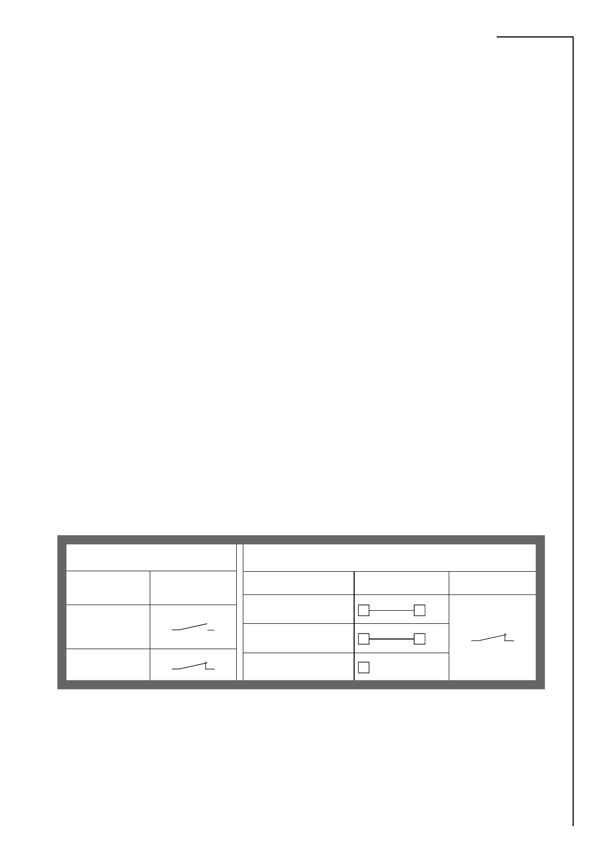
Tab. 2.3.1. BKS 24 -9A contacts K1 and K2
K1 Function Contact
Situation State
Current Failure
15 16
No Failure
15 16
Programming K2 Auxiliary Contact
Function Interconnection State
K2 contact is on if all the
damperss are open 14 11
17 18
K2 contact is on if the damper
No. 1 is open 14 12
K2 contact is on if all the
dampers are closed 14 open
Function check can be done in the position OPERATION by means of pushing the TEST
button. While the button is pushed, the flap blade is turning into the position FAILURE. Fault
function is indicated by a report "FAILURE".
2.4.
Design of the FDMD in terms of design. It shall be marked with the first and second additional digit
after the dot in the ordering key.