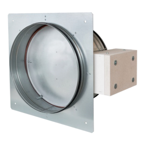
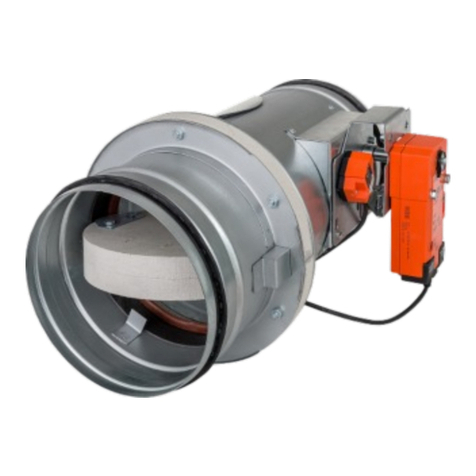
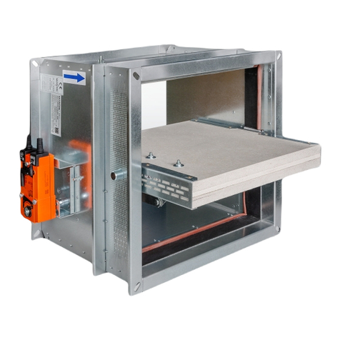
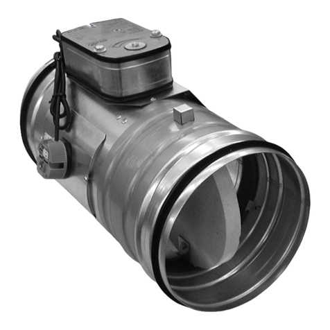
Mandik FDMC User manual

FDMC, FDMC-SRD
TPM 083/12-DK
VALID FROM: 15/1/2012
FIRE DAMPER AND FIRE DAMPER-SMOKE RELIEF

TPM 083/12
2
Park Allé 366, DK-2605 Brondby
These technical specifications state a row of manufactured sizes and models of fire dampers and fire dampers - smoke
relief (further only dampers) FDMC, FDMC-SRD. It is valid for production, designing, ordering, delivery, assembly and
operation.
II. GENERAL INFORMATION 3
1. Description......................................................................................................................... 3
2. Design................................................................................................................................ 4
3. Dimensions, weights........................................................................................................... 5
4. Placement and Assembly.................................................................................................... 6
5. Statement of installations.................................................................................................... 8
III. TECHNICAL DATA 9
6. Pressure loss...................................................................................................................... 9
7. Coefficient of local pressure loss......................................................................................... 10
8. Noise data........................................................................................................................... 10
9. Electrical Components, Connection Diagrams.................................................................... 12
IV. ORDERING INFORMATION 13
10. Ordering key..................................................................................................................... 13
V. MATERIAL, FINISHING 13
11. Material............................................................................................................................. 13
VI. INSPECTION, TESTING 13
12. Inspection, testing............................................................................................................. 13
VII. TRANSPORTATION AND STORAGE 14
13. Logistic terms.................................................................................................................... 14
VIII. ASSEMBLY, ATTENDANCE, MAINTENANCE AND REVISIONS 14
14. Assembly.......................................................................................................................... 14
15. Entry into service and revisions......................................................................................... 14
I. CONTENT

TPM 083/12
3
Park Allé 366, DK-2605 Brondby
II. GENERAL INFORMATION
1. Description
1.1.
Fire dampers are shutters in piping systems of air-conditioning devices that prevent spreading
the fire and combustion products from one fire segment to the other one by means of closing the
air piping in the points of fire separating constructions.
1.4.
The damper is sealed with a silicon packing against smoke penetration after closing the blade. At
the same time, the damper blade is bed in a material which enlarges its capacity and air proofs
the air duct.
1.3.
Dampers blade automatically closes air duct using an actuating mechanism back spring. The
back spring of the actuating mechanism is started when the thermoelectrical starting mechanism
BAE 72B-S is activated, when a reset button on BAE 72B-S is pushed or when a power supply
of the actuating mechanism is stopped (for FDMC-SRD only when the power supply of the
actuating mechanism is stopped).
1.2.
Dampers are in all variants classified as EI 60 ve, ho (i o) S acc. EN 13501-3 and tested acc.
EN 1366-2.
1.5.
Dampers have one inspection hole, since the shutting device and the inspection hole can be set
into the most advantageous position (with respect to the operation and manipulation with the
control device).
1.6.
Exact damper function is provided under the following conditions:
a) Maximum air circulation speed: 12 m.s
-1
Maximum pressure difference: 1200 Pa
b) Dampers could be displaced into position “CLOSED” only in case that ventilator, or Ai
r
Handling Unit is switched off. The goal is the securing of proper closing and safe
function of Fire Damper in case of Fire.
c) The air circulation in the whole damper section must be secured as steady on whole
surface.
1.7.
Dampers are designed for macroclimatic areas with mild climate according to EN 60 721-3-3.
1.8.
Dampers are suitable for systems without abrasive, chemical and adhesive particles.
1.9.
Temperature in the place of installation is permitted to range from - 20°C to + 50°C.
1.11.
In this document are used next signs and units.
Key :
w[m.s
-1
] air velocity
p [Pa] pressure loss
L
w
[dB] level of acoustic output
[ ] pressure loss coefficient
[kg.m
-3
] density
A,B, a, c,
e, f
[mm] dimension
S [m
2
]area
1.10.
If is not noticed other way, all dimensions and weight are in millimeters and kilograms.

TPM 083/12
4
Park Allé 366, DK-2605 Brondby
2. Design
2.1.
FDMC is always equipped by actuating mechanism BLF 24-T-ST (further only "actuating
mechanism"). After being connected to power supply AC/DC 24V, the actuating mechanism
displaces the damper blade into operation position "OPEN" and at the same time it pre-stretches
its back spring. When the actuating mechanism is under voltage, the damper blade is in the
position "OPEN" and the back spring is pre-stretched. Time needed for full opening of the flap
blade from the position "CLOSED" to the position "OPEN" is maximum 140s. If the actuating
power supply is cut off (due to loss of supply voltage, activation of thermoelectrical actuating
mechanism or pushing the reset button on the thermoelectrical starting mechanism BAE 72B-S),
the back spring displaces the damper blade into the breakdown position "CLOSED". The time o
f
displacing the blade from the position "OPEN" to the position "CLOSED" takes maximum 16 s. In
case that the power supply is restored again (the blade can be in any position), the actuating
mechanism starts to re-displace the damper blade into the position "OPEN".
A thermoelectrical starting mechanism BAE 72B-S, which contains three thermal fuses Tf1 and
Tf2/Tf3, is a part of the actuating mechanism. These fuses are activated when temperature
+72 °C has been exceeded (the fuse Tf1 when the temperature around the damper and the fuses
Tf2/Tf3 when the temperature inside the air-conditioning piping has been exceeded). After the
thermal fuse Tf1 or Tf2/Tf3 has been activated, the power supply is permanently and irreversibly
cut off and the actuating mechanism, by means of the pre-stretched spring, displaces the dampe
r
blade into the breakdown position "CLOSED".
2.2.
FDMC-SRD is always equipped by actuating mechanism BLF 24-ST. It is without BAE 72B-S.
Function is similar to the BLF 24-T-ST. After being connected to power supply AC/DC 24V, the
actuating mechanism displaces the damper blade into operation position "OPEN" and at the
same time it pre-stretches its back spring. When the actuating mechanism is under voltage, the
damper blade is in the position "OPEN" and the back spring is pre-stretched. Time needed for full
opening of the flap blade from the position "CLOSED" to the position "OPEN" is maximum 140s.
If the actuating power supply is cut off (due to loss of supply voltage), the back spring displaces
the damper blade into the breakdown position "CLOSED". The time of displacing the blade from
the position "OPEN" to the position "CLOSED" takes maximum 16 s. In case that the powe
r
supply is restored again (the blade can be in any position), the actuating mechanism starts to
re-displace the damper blade into the position "OPEN".
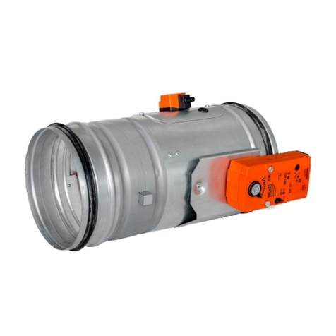
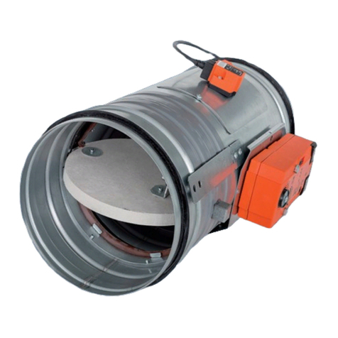
Fig. 1
FDMC FDMC-SRD

TPM 083/12
5
Park Allé 366, DK-2605 Brondby
Position:
1 Damper body 4 BAE 72B-S thermoelectrical starting mechanism
2 Damper blade 5 Inspection hole covering
3 Actuating mechanism
Fig. 2 Fire damper FDMC
Fig. 3 Fire damper smoke relief FDMC-SRD
3. Dimestions, weights
3.1.
Dimensions

TPM 083/12
6
Park Allé 366, DK-2605 Brondby
Tab. 3.2.1. Weight and effective area
Size
D a Weight
Effective area
S
ef
[m
2
]Actuating mechanism
100
-3,1 0,0036 BLF
125
-3,4 0,0068 BLF
140
-3,6 0,0092 BLF
150
-3,7 0,0109 BLF
160
-3,8 0,0129 BLF
180
-4,1 0,0172 BLF
200
-4,4 0,0222 BLF
225
-4,7 0,0293 BLF
250
95,5 0,0374 BLF
280
24 6,0 0,0484 BLF
315
41,5 6,6 0,0630 BLF
350
59 7,0 0,0793 BLF
355
61,5 7,3 0,0821 BLF
400
84 8,2 0,1065 BLF
3.2.
Weight and effective area
4. Placement and Assembly
4.1.
Fire dampers are suitable for installation in arbitrary position in vertical and horizontal passages
of fire separating constructions. Damper assembly procedures must be done so as all load
transfer from the fire separating constructions to the damper body is absolutely excluded.
Back-to-back air-conditioning piping must be hung or supported so as all load transfer from the
back-to-back piping to the damper is absolutely excluded.
3.3.
For fire damper the open damper blade overlaps the damper body from dimension 250 by the
“a” value. These values are specified in the Tab. 3.2.1
Value has to be respected when projecting related air-conditioning piping.
Fig. 4 Value “a”

TPM 083/12
7
Park Allé 366, DK-2605 Brondby
Fig. 5 Placement of the openings in the wall
min. 75
min. 75
min. 200
4.4.
The control mechanism has to be protected (covered) against damage and pollution during
installation process.
4.5.
All fire dampers has to be closed during installation process. The damper body should not be
deformed in the course of bricking in. Once the damper is built in, its blade should not grind on
the damper body during opening or closing.
4.7.
Installation opening dimensions
4.2.
To provide needed access space to the control device, all other objects must be situated at least
350 mm from the control parts of the damper. Inspection hole must be accessible.
4.3.
The distance between the fire damper and the construction (wall, ceiling) must be minimum
75 mm. In case that two or more dampers are supposed to be installed in one fire separating
construction, the distance between the adjacent dampers must be at least 200 mm according to
EN 1366-2 paragraph 13.5.
Fig. 6 Installation opening dimensions
4.6.
Round dampers are with rubber tightness and glued all the way around.

TPM 083/12
8
Park Allé 366, DK-2605 Brondby
5. Statement of installations
5.1.
Statement of installations
Tab. 5.1.1. Statement of installations
Damper
size FDMC installation Classifi-
cation Figure
100-400
Damper installed on a solid wall construction. Space between damper and
wall is filled by mortar, gypsum or another approved fire sealing system
for damper installation.
EIS 60 7
Damper installed on a gypsum wall construction. Space between damper
and wall is filled by mortar, gypsum or another approved fire sealing
system for damper installation.
EIS 60 8
Damper installed on a solid ceiling construction. Space between damper
and ceiling is filled by mortar, gypsum or another approved fire sealing
system for damper installation.
EIS 60 9
Duct ended by installation shaft. Space between damper and ceiling is
filled by mortar, gypsum or another approved fire sealing system for
damper installation - solid wall construction
EIS 60 10
Duct ended by installation shaft. Space between damper and ceiling is
filled by mortar, gypsum or another approved fire sealing system for
damper installation - gypsum wall construction
EIS 60 11
Fig. 7 Installation on a solid wall construction
Position:
1 Fire damper FDMC
2 Mortar or gypsum with min. density 800 kg/m
3
or another approved fire
sealing system for damper installation
2
1
2
1

TPM 083/12
9
Park Allé 366, DK-2605 Brondby
Position:
1 Fire damper FDMC
2 Mortar or gypsum with min. density 800 kg/m
3
or another approved fire
sealing system for damper installation
Fig. 8 Installation on a gypsum wall construction
2
1
2
1
Fig. 9 Installation on a ceiling wall construction
1
2
2
1
Position:
1 Fire damper FDMC
2 Mortar or gypsum with min. density 800 kg/m
3
or another approved fire
sealing system for damper installation

TPM 083/12
10
Park Allé 366, DK-2605 Brondby
Fig. 11 Duct ended by installation shaft - gypsum wall construction
Fig. 10 Duct ended by installation shaft - solid wall construction
4
Position:
1 Fire damper FDMC 3 Duct
2 Mortar or gypsum with min. density 800 kg/m
3
or another
approved fire sealing system for damper installation
4 Installation shaft
3
1
2
1
3
2
4
4
Position:
1 Fire damper FDMC 3 Duct
2 Mortar or gypsum with min. density 800 kg/m
3
or another
approved fire sealing system for damper installation
4 Installation shaft
3
1
2
1
3
2
4

TPM 083/12
11
Park Allé 366, DK-2605 Brondby
6. Pressure loss
6.1.
Pressure loss calculation
p = w
2
2
p [Pa] presure loss
w[m.s
-1
] air flow speed in nominal damper section
[kg.m
-3
] air density
[-] coefficient of local pressure loss for the nominal damper section
(see Tab. 7.1.1.)
III. TECHNICAL DATA
6.2.
Determination of pressure loss by using diagram 6.2.1. = 1,2 kg.m
-3
Diagram 6.2.1. Pressure losses for air density =1,2 kg.m
-3
7.1.
Coefficient of local pressure loss (-)
Tab. 7.1.1. Coefficient of local pressure loss
D 100 125 140 150 160 180 200 225 250 280 315 350 355 400
2,736 2,099 1,781 1,527 1,272 0,929 0,636 0,477 0,344 0,237 0,159 0,125 0,116 0,085
7. Coefficient of local pressure loss

TPM 083/12
12
Park Allé 366, DK-2605 Brondby
8. Noise data
8.1.
Level of acoustic output corrected with filter A.
L
WA
[dB(A)] level of acoustic output corrected with filter A
L
W1
[dB] level of acoustic output L
W1
related to the 1 m
2
section (see Tab. 8.3.1.)
S[m
2
] effective area of the damper
K
A
[dB] correction to the weight filter A (see Tab. 8.3.2.)
L
WA
= L
W1
+ 10 log(S) + K
A
8.2.
Level of acoustic output in octave ranges.
L
Woct
[dB] spectrum of acoustic output in octave range
L
W1
[dB] level of acoustic output L
W1
related to the 1 m
2
section (see Tab. 8.3.1.)
S[m
2
] effective area of the damper
L
rel
[dB] relative level expressing the shape of the spectrum (see Tab. 8.3.3.)
L
Woct
= L
W1
+ 10 log(S) + L
rel
8.3.
Table of acoustics values
Tab. 8.3.1. Level of acoustic output L
W1
related to the 1 m
2
section
[-]
w [m.s
-1
] 0,1 0,2 0,3 0,4 0,6 0,8 1 1,5 2 2,5 3 3,5
2
9,0 11,5 14,7 16,9 20,1 22,3 24,1 27,2 29,4 31,2 32,6 33,8
3
16,7 22,1 25,3 27,5 30,7 32,9 34,6 37,8 40,0 41,7 43,2 44,4
4
24,2 29,6 32,8 35,0 38,1 40,4 42,1 45,3 47,5 49,2 50,7 51,9
5
30,0 35,4 38,6 40,8 44,0 46,2 47,9 51,1 53,3 55,1 56,5 57,7
6
34,8 40,2 43,3 45,6 48,7 51,0 52,7 55,8 58,1 59,8 61,2 62,4
7
38,8 44,2 47,3 49,6 52,7 55,0 56,7 59,9 62,1 63,8 65,2 66,4
8
42,3 47,7 50,8 53,1 56,2 58,4 60,2 63,3 65,6 67,3 68,7 69,9
9
45,4 50,7 53,9 56,1 59,3 61,5 63,3 66,4 68,6 70,4 71,8 73,0
10
48,1 53,5 56,6 58,9 62,0 64,3 66,0 69,1 71,4 73,1 74,5 75,7
11
50,6 56,0 59,1 61,4 64,5 66,7 68,5 71,6 73,9 75,6 77,0 78,2
12
52,8 58,2 61,4 63,6 66,8 69,0 70,7 73,9 76,1 77,9 79,3 80,5

TPM 083/12
13
Park Allé 366, DK-2605 Brondby
Fig. 12 Calculation example
Given data: Fire damper FDMC 250
V = 1000 m
3
.h
-1
= 1,2 kg.m
-3
Octave range 1000 Hz
Tab. 3.2.1. S
ef
= 0,0374 m
2
Calculation : w [m.s
-1
] = (V [m
3
.h
-1
] / 3600) / S
ef
[m
2
]
w = 7,43 m.s
-1
Tab. 7.1.1. = 0,344
Calculation : p = . . (w
2
/2) = 0,344 . 1,2 . (7,43
2
/2) = 11,4 Pa
Tab. 8.3.1., Tab. 8.3.2. and
Tab. 8.3.3.
L
W1
= 48,8 dB
K
A
= - 6,1 dB
L
rel
= -11,5 dB (for1000 Hz)
Calculation : L
WA
= L
W1
+ 10 log(S
ef
) + K
A
= 48,8 + 10 log(0,0374) - 6,1 = 28,5 dB
L
Woct
= L
W1
+ 10 log(S
ef
) + L
rel
= 48,8 + 10 log(0,0374) - 11,5 = 23,1 dB
Tab. 8.3.2. Correction to the weight filter A
w [m.s
-1
] 2 3 4 5 6 7 8 9 10 11 12
K
A
[dB]
-15,0 -11,8 -9,8 -8,4 -7,3 -6,4 -5,7 -5,0 -4,5 -4,0 -3,6
Tab. 8.3.3. Relative level expressing the shape of the spectrum L
rel
f [Hz]
w [m.s
-1
] 63 125 250 500 1000 2000 4000 8000
2
-4,5 -6,9 -10,9 -16,7 -24,1 -33,2 -43,9 -56,4
3
-3,9 -5,3 -8,4 -13,1 -19,5 -27,6 -37,4 -48,9
4
-3,9 -4,5 -6,9 -10,9 -16,7 -24,1 -33,2 -43,9
5
-4,0 -4,1 -5,9 -9,4 -14,6 -21,5 -30,0 -40,3
6
-4,2 -3,9 -5,3 -8,4 -13,1 -19,5 -27,6 -37,4
7
-4,5 -3,9 -4,9 -7,5 -11,9 -17,9 -25,7 -35,1
8
-4,9 -3,9 -4,5 -6,9 -10,9 -16,7 -24,1 -33,2
9
-5,2 -3,9 -4,3 -6,4 -10,1 -15,6 -22,7 -31,5
10
-5,5 -4,0 -4,1 -5,9 -9,4 -14,6 -21,5 -30,0
11
-5,9 -4,1 -4,0 -5,6 -8,9 -13,8 -20,4 -28,8
12
-6,2 -4,3 -3,9 -5,3 -8,4 -13,1 -19,5 -27,6

TPM 083/12
14
Park Allé 366, DK-2605 Brondby
Fig. 13 Actuating mechanism BELIMO BLF 24-T-ST
9. Electrical Components, Connection Diagrams
9.1.
Actuating mechanism
Tab. 9.1.1. Actuating mechanism BELIMO BLF 24-T-ST (24-ST)
Servopohon BELIMO BLF 24-T-ST(24-ST)
Nominal voltage AC 24V 50/60Hz
DC 24 V
Power consumption - motoring
- holding
5 W
2,5 W
Dimensioning 7 VA (Imax 5,8 A @ 5 ms)
Protection Class III
Degree of protection IP 54
Running time - motor
- spring return
40..75 s
~ 20 s
Ambient Temperature - normal duty
- safety duty
- non-operating temperature
- 30 °C … + 50 °C
The safe position will be attained up to max. 75°C
- 40 °C … + 50 °C
Connecting - motor
- auxiliary switch
cable 1 m, 2 x 0,75 mm
2
with 3 pole plug
cable 1 m, 6 x 0,75 mm
2
with 6 pole plug
Thermal trips* Tf1: duct outside temperature 72°C
Tf2/Tf3: duct inside temperature 72°C
* only BLF 24-T-ST
Fig. 14 Actuating mechanism BELIMO BLF 24-ST

TPM 083/12
15
Park Allé 366, DK-2605 Brondby
11. Material
V. MATERIAL, FINISHING
11.1.
Damper bodies are supplied in the design made of galvanized plate without any other surface
finish.
11.2.
Damper blades are made of fire resistant asbestos free boards made of mineral fibres.
11.3.
Fasteners is galvanized.
VI. INSPECTION, TESTING
12. Inspection, testing
12.1.
The appliance is constructed and and preset by the manufacturer, its operation is dependent on
proper installation and adjustment.
IV. ORDERING INFORMATION
10. Ordering key
technical specifications
size
type (FDMC, FDMC-SRD)
FDMC 180 TPM 083/12-DK
VIII. ASSEMBLY, ATTENDANCE, MAINTENANCE AND REVISIONS
14. Assembly
14.1.
All effective safety standards and directives must be observed during fire damper assembly.
14.2.
To ensure reliable fire damper function it is necessary to avoid blocking the closing mechanism
and contact surfaces with collected dust, fibre and sticky materials and solvents.
13. Logistic terms
13.1.
Dampers are transported by box freight vehicles without direct weather impact, there must not
occur any sharp shocks and ambient temperature must not exceed + 40 °C. Dampers must be
protected against mechanic damages when transported and manipulated. During transportation,
the damper blade must be in the "CLOSED" position.
VII. TRANSPORTATION AND STORAGE
13.2.
Dampers are stored indoor in environment without any aggressive vapours, gases or dust. Indoo
r
temperature must be in the range from -5 °C to +40 °C and maximum relative humidity 80 %.
Dampers must be protected against mechanic damages when transported and manipulated.
14.3.
Manual operation
Without power supply, the damper can be operated manually and fixed in any required
position. Release of the locking mechanism can be achieved manually or automatically
by applying the supply voltage.

TPM 083/12
16
Park Allé 366, DK-2605 Brondby
The producer reserves the right for innovations of the product. For actual product information see
www.mandik.com
MANDÍK a.s.
Dobříšská 550
26724 Hostomice
Česká Republika
Tel.: +420 311 706 706
Fax: +420 311 584 810, 311 584 382
E-Mail: [email protected]
www.mandik.com
Your distributor
15. Entry into service and revisions
15.1.
Before entering the dampers into operation after assembly and after sequential revisions, checks
and functionality tests of all designs including operation of the electrical components must be
done. After entering into operation, these revisions must be done according to requirement set
by national regulations.
15.1.1.
In case that dampers are found unable to serve for their function for any cause, it must be clearly
marked. The operator is obliged to ensure so that the damper is put into condition in which it is
able to function and meanwhile he is obliged to provide the fire protection another appropriate
way.
15.2.
Before entering the dampers into operation after their assembly and by sequential checks, the
following checks must be carried out.
15.2.1.
Visual inspection of proper damper integration, inside damper area, damper blade, contact
surfaces and silicon sealing.
15.2.2.
Inspection hole disassembly: release the covering lid by unscrewing screws. Then tilt remove lid
from its original position.
15.1.2.
Results of regular checks, imperfections found and all-important facts connected with the dampe
r
function must be recorded in the "FIRE BOOK" and immediately reported to the operator.
15.2.3.
Check of blade displacement into the breakdown position "CLOSED" can be done after cutting
off the actuating mechanism supply (e.g. by pressing the RESET button at the thermoelectrical
starting mechanism BAE 72B-S - only FDMC or cutting off the supply from ELECTRICAL FIRE
SIGNALISATION). Check of blade displacement back into the "OPEN" position can be done afte
r
restoration of power supply (e.g. By releasing the RESET button - only FDMC or restoration o
f
supply from ELECTRICAL FIRE SIGNALISATION).
Other manuals for FDMC
3
This manual suits for next models
1
Table of contents
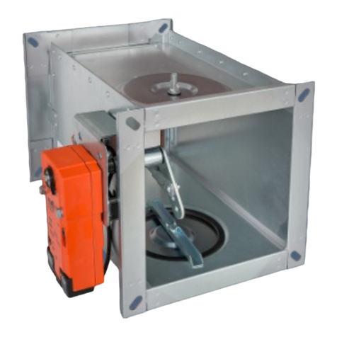
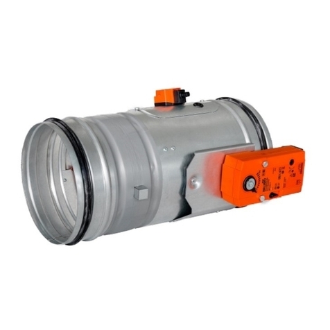
Other Mandik Fire And Smoke Damper manuals
Popular Fire And Smoke Damper manuals by other brands

VPro
VPro WT instruction manual

Trox Technik
Trox Technik EK-EU Installation and operating manual

Komfovent
Komfovent LMV-D3-MF-F installation instructions

Greenheck
Greenheck VCD Series Installation, operation and maintenance manual

Arzel
Arzel Heat PumPro Installation & operation instructions

MAT
MAT Roto-Twist RT-150 Series Installation & operation instructions