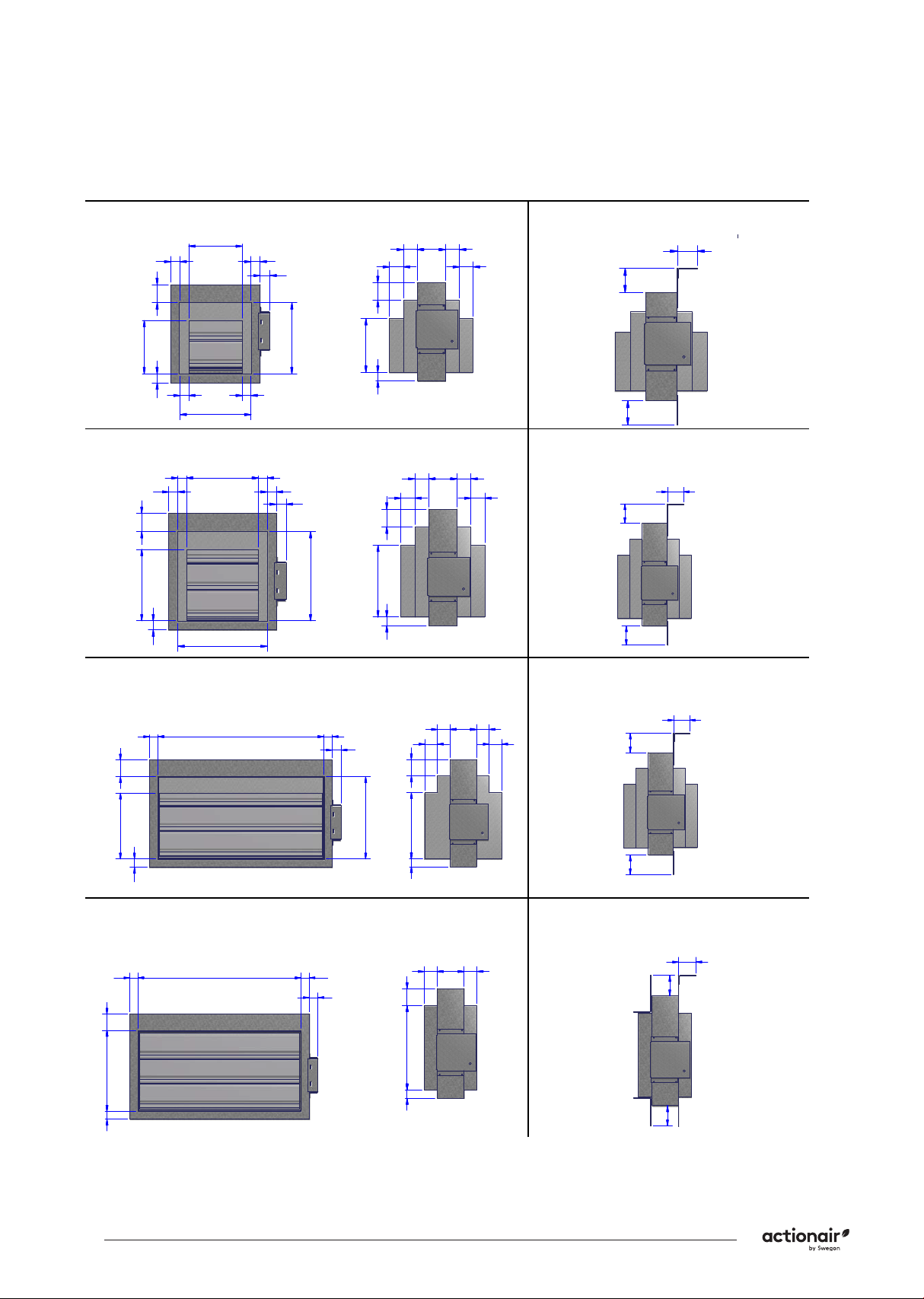
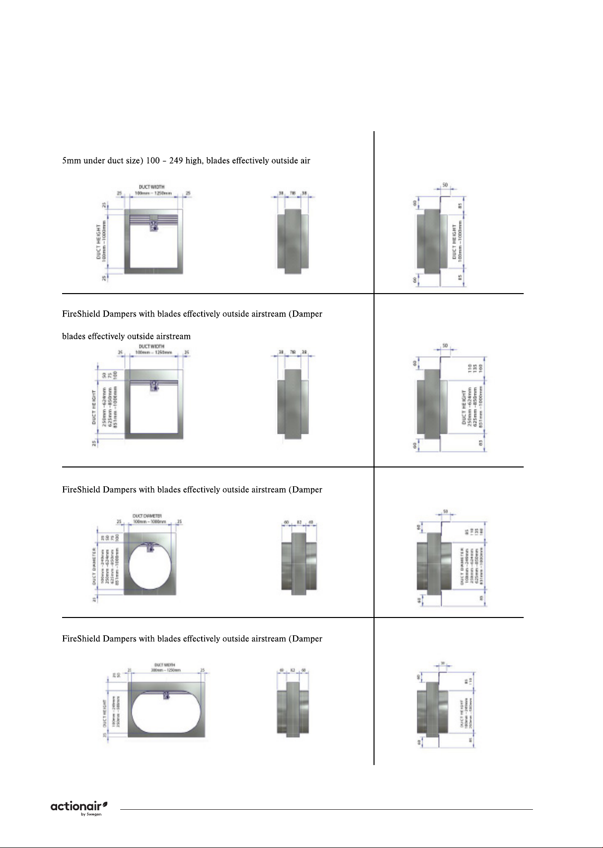
Actionair DWFX-F Installation Guide
10 Swegon reserves the right to alter specications. 20210408 - LNNN00354 (3.0)
Periodic Maintenance
Manufacturer Recommended Service Inter-
vals
• After commissioning and handover (see DW145 check
sheet), in order to remain compliant with 15650:2010,
we recommend that you follow a regular service and
inspection programme to ensure correct operation
of dampers in the event the damper is required to
actuate.
• In addition to regular physical inspections (in accor-
dance with 15650:2010) we recommend using a
dedicated damper control panel with a digital reporting
mechanism (such as an Actionpac LNS system) to fre-
quently monitor and report on regular remote damper
testing.
• Ensure maintenance is performed in line with the latest
best practice and relevant local or specialist guidance.
• Our recommended service intervals for life safety pro-
ducts are as follows:
Interval Action Competence
6 Months Check Actuator Wiring (if appli-
cable) for Damage
Specialist
Persons
6 Months Check Limit Switch Wiring (if
applicable) for Damage
Specialist
Persons
6 Months Check Damper Cleanliness, Clean
and Lubricate if necessary.
Specialist
Persons
6 Months Check Condition of Blades and
Seals, report and rectify if neces-
sary.
Specialist
Persons
6 Months Check for blade obstructions Specialist
Persons
6 Months Check Damper Release Me-
chanism (through activation or
release of the ETR or Thermal
Fuse Device)
Specialist
Persons
6 Months Check damper is left in normal
operational position after inspec-
tion.
Specialist
Persons
Monthly Complete actuation of damper
from control panel (if installed)
and check all faults. Consult spe-
cialist persons to investigate any
reported faults.
Facility Ma-
nager
• *Specialist Persons: A recognised and experienced
person with prior experience in the inspection and
assessment of the functional safety of smoke and re
damper products. If in doubt, please consult with our
technical support team for advice. To talk about our
OEM maintenance inspections, contact our nationwide
service team.
BS EN 15650:2010 - Ventilation for Buildings
- Fire Dampers
• Section 8.3 states regular testing/ inspection should
be undertaken to meet regulatory requirements, or at
intervals not exceeding six months.
• A comprehensive example of the maintenance pro-
cedure is given in Annex D of the standard. Some
automatic systems may allow more frequent testing
(48hr or less) and this may be required by a national
standard.
Approved Document B, Volume 2
• Clause 10.12 states adequate means of access must be
provided to allow inspection, testing and maintenance
of both re damper and its actuating mechanism.
BS 9999:2017 - Code of Practice for the Fire
Safety in the Design, Management and Use
of Buildings - Annex I
Smoke Control Systems
• For means of escape states actuation of the system
should be simulated once a week. It should be ensured
that any fans and powered exhaust ventilators ope-
rate correctly, smoke dampers close (or open in some
systems), natural exhaust ventilators open, automatic
smoke curtains move into position, etc.
Three Monthly
• In addition to the checks recommended in V.2, V.3 and
V.4, the actuation of all smoke control systems should
be simulated once every three months. All zones should
be separately tested and it should be ensured that any
fans and powered exhaust ventilators operate correctly,
smoke dampers close (or open in some systems) etc.
Yearly
• In addition to the following checks should be made for
annual inspections and tests of the following to be car-
ried out by competent persons, for any defects to be
logged and the necessary action taken, and for certi-
cates of testing to be obtained.
– Fire detection and re alarm systems;
– Self-contained luminaires with sealed batteries, if more
than 3 years old;
– Sprinkler, drencher and watermist systems;
– Smoke ventilators and smoke control systems;
– Fire dampers
BS 9999:2017 - Code of Practice for the Fire
Safety in the Design, Management and Use
of Buildings - Annex W
• Maintenance of air conditioning and ventilation equip-
ment including air lters, motors, re dampers and
their controls, smoke detectors and alarms is of para-
mount importance both in preventing re and in ensur-
ing that measures taken to mitigate its consequences
are effective when needed. Arrangements should be
made for all re dampers to be tested by a competent
person on completion of the installation and at regular
intervals not exceeding 2 years. They are to be repaired
or replaced immediately if found to be faulty. Spring
operated re dampers should be tested annually and
re dampers in dust laden and similar atmospheres
should be tested much more frequently, at periods
suited to the degree of pollution.