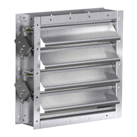
Industrial Damper
Installation, Operation, and Maintenance Manual
Bearings
Jamb Seal
Stop Seal
Blade Seal
1. Clean the dampers. Over time, dirt and
grime may collect on damper surfaces.
This can be a hindrance to airflow as
well as reduce the sealing efficiency of
the damper when closed. Be especially
careful in cleaning non-metallic blade
seals as they can be torn if abused. Mild
soap and water is the recommended
cleaning agent. Avoid abrasives and
solvents as these could degrade seals,
adhesives, oil on bearings, etc.
2. Check moving parts such as crank arms,
linkages, pins, blades, etc., to make sure
they move freely. While not required,
lubricating these components can prevent
possible rusting and unnecessary friction
increase. Use only a molybdenum spray
oil or similar graphite-based oil as regular
lubricating oil will attract dirt.
3. The bearings located on the blade axles
do not require lubrication.
4. If installed, inspect the blade seals and
stop seals for damage such as tears and
nicks. If damaged, replace as needed.
5. Check for worn shaft seals if applicable
and repair or replace as necessary.
6. Look for debris that may be interfering
with blade closure or effective sealing of
the blades and remove.
7. Check for loose hardware.
Refer to the actuator installation manual
for details on the actuator maintenance
requirements as well.
Industrial Damper IOM 2 of 3, January, 2023 pottorff.com
If any NEMA electrical enclosure is supplied, use appropriate electrical
connections to maintain the NEMA rating. All wiring and fusing must
be in accordance with national electric code, local code, and project
specification requirements. If the unit is supplied with an actuator, refer to
the actuator installation manual for details on the actuator before startup
as well.
If pneumatic power is required, check all pneumatic connections. The
supplied pressures must match the pressures required. A qualified
technician must be used. Improper connections are hazardous and can
cause permanent damage to the pneumatic equipment. All plumbing
must be in accordance with national code, local code, and project
specification requirements. If the unit is supplied with an actuator, refer to
the actuator installation manual for details on the actuator before startup
as well.
Maintenance
Pottorff dampers are designed to be maintenance free under normal
operation. Dampers are to be installed square, level, and straight to
prevent binding during operation. The following damper maintenance is
suggested to help ensure proper operation and increase life expectancy
of the damper. The frequency of maintenance should be determined by
the severity of the application. Before performing maintenance ensure
that the damper has been locked out. The blades should also be securely
blocked to eliminate the potential for movement while maintaining.
Single Section Dampers
If damper is supplied without mounting holes, drill or punch as required.
Pottorff is not responsible for corrosion around field punched or drilled
holes on painted dampers. Unless specifically designed for vertical
blades, damper must be mounted with blade axis horizontal. Connect the
damper to the mounting location using the proper hardware. Attach the
damper to all connection points before tightening bolts. Confirm that the
damper is square, straight, and level, and free from bending, twisting, or
racking. Manually operate the damper to ensure that it operates freely.
Multi-Section Dampers
Follow instructions for single section dampers. Additionally, position
damper sections together in opening or duct. Align and match frame
markings or labels on adjacent sections. Fasten adjacent sections
together on front and back sides with screws or nuts and bolts. Shim
damper frame and opening or duct as required to prevent distortion of
frame. Multi-section dampers require bracing to support the weight of
the assembly and to hold against system pressure. Bracing should
support the damper horizontally, minimum 8 feet center-to-center. Large
vertical assemblies and high system pressure may require additional
bracing. All additional bracing and supports designed, supplied, and
installed by others.
Do's
1. DO use provided lifting lugs.
2. DO install bolts into all supplied mounting holes, then tighten in an
even and staggered pattern to evenly compress the flange gasket (if
using).
3. DO check that the mating flange is flat, square, and parallel to the
damper flange.
4. DO check that damper blade(s) and linkages do not interfere with the
mating opening or duct when the damper is cycled between open
and closed positions.
Don'ts
1. DO NOT lift damper by blade(s).
2. DO NOT use actuator, linkage, or axles as lifting point.
3. DO NOT pry flanges to mate flange holes with opening or duct
flange as the frame could become warped, twisted, bent, or pulled
out-of-round causing binding.
4. DO NOT tighten mounting bolts by working around damper.
Please follow these instructions carefully. Failure to do so may void the
warranty. If the unit is supplied with an actuator, refer to the actuator
installation manual for details on the actuator before installation as well.
If the actuators were factory installed some adjustment may be required
after installation.
Start Up
Precautions should be taken before startup of the damper. All additional
safety accessories should be installed before starting the damper to
ensure the safety of everyone around. Rotate the blade(s) by hand to
ensure free movement of all components. Remove any construction
debris, loose hardware, tools, etc., from inside the damper and opening
or duct.
If electrical power is required, check all electrical connections before
turning on power. The supplied voltage must match the voltage required.
A qualified electrician must be used. Improper connections are hazardous
and can cause permanent damage to the electrical equipment.
