AeroClave mRDS User manual

ROOM DECONTAMINATION SYSTEM
OPERATOR MANUAL
Model(s): mRDS
This document contains informaon which is proprietary to AeroClave, LLC. Accordingly, the infor-
maon in this document shall not be disclosed outside the customer’s organizaon and shall not be
duplicated, used or disclosed – in whole or in part – for any purpose other than to evaluate this infor-
maon. This restricon does not limit the customer’s right to use informaon contained in this docu-
ment if it is obtained from another source without restricon. The data subject to this restricon are
contained in all sheets of this document.
This technical data is controlled under the Export Administraon Regulaons, and may not be exported
to a Foreign Person, either in the U.S. or abroad, without the proper authorizaon of the U.S. Depart-
ment of Commerce.

AeroClave mRDS Operator Manual
Released January 8, 2016 Page 2
Use or disclosure of data contained on this sheet is subject to the restriction on the cover page of this User’s Manual.
TABLE OF CONTENTS
1.0 INTRODUCTION ............................................................................................................... 3
1.1 Purpose ..........................................................................................................................3
1.2 Terms/Definitions .........................................................................................................3
1.3 Equipment and Media ...................................................................................................3
2.0 SAFETY GUIDELINES ..................................................................................................... 4
2.1 Operational Safety Guidelines ......................................................................................4
2.2 Operator Qualification ..................................................................................................5
3.0 PRODUCT DESCRIPTION ............................................................................................... 6
3.1 Technical Specifications ...............................................................................................6
4.0 SET-UP/OPERATION......................................................................................................... 6
4.1 Pre-decontamination Set-up..………………….............................................................6
4.2 Decontamination Cycle Start ..……..............................................................................7
4.3 Decontamination Cycle Operation.................................................................................9
4.4 Emergency Stop Operation………..……….…...........................................................13
5.0 PREVENTATIVE MAINTENANCE.…………………………………………………….15
5.1 General Guidelines…………………………………………………………………...15
5.2 Maintenance Steps……………………………………………………………………15
6.0 MISCELLANEOUS........................................................................................................... 16
6.1 Configuration....…………….…………..…….............................................................16

AeroClave mRDS Operator Manual
Released January 8, 2016 Page 3
Use or disclosure of data contained on this sheet is subject to the restriction on the cover page of this User’s Manual.
1.0 INTRODUCTION
1.1 Purpose
The purpose of this manual, primarily, is to establish guidelines for the safe operation of the mRDS
system. Secondarily, it establishes a method for proper hand-application using the optional APA.
1.2 Terms/Definitions
mRDS: modular Room Decontamination System
APA: AeroClave Portable Applicator
Injection Phase: In this phase, the solution is aerosolized and applied evenly to the
treatment area. A typical injection phase can last anywhere from 5-30
minutes, depending on the size of the treatment area.
Dwell Phase: Once an injection phase has completed, the treatment area is allowed to sit
for a minimum of 10 minutes in a dwell period. The dwell period gives the
aerosolized solution an opportunity to evenly distribute throughout the
treatment area, ensuring complete coverage on all surfaces.
Aeration Phase: The aeration phase is the final stage when the treatment area is returned to
its normal habitable state. Do not re-enter the area until the air is clear
(minimum 20 minutes).
1.3 Equipment and Media
mRDS Unit
4 Liter AeroClave Solution Tank
AeroClave Approved Solution
APA
Touchscreen Controller

AeroClave mRDS Operator Manual
Released January 8, 2016 Page 4
Use or disclosure of data contained on this sheet is subject to the restriction on the cover page of this User’s Manual.
2.0 SAFETY GUIDELINES
READ AND UNDERSTAND THIS OPERATOR’S MANUAL PRIOR TO USE OF THE SYSTEM.
STRICTLY FOLLOW ALL SAFETY INSTRUCTIONS IN THIS OPERATOR’S MANUAL
PRIOR TO, DURING, AND AFTER USE OF THE SYSTEM. SYSTEM OPERATOR’S MUST
COMPLY WITH ALL SAFETY PRECAUTIONS MENTIONED IN THIS SECTION.
Use only AeroClave-approved solutions when operating this equipment. Failure to do so will result
in voiding of warranty and may result in INJURY or DEATH. Follow all label instructions on ap-
proved solutions.
2.1 Operational Safety Guidelines
2.1.1 Only trained and qualified personnel should operate the mRDS unit.
2.1.2 Levels of training:
a) Demonstration Training: individuals who will be operating the mRDS unit for
demonstration purposes only, using only de-ionized or distilled water as a surro-
gate solution must read and understand this document.
b) mRDS Operator Training: individuals who will be operating the mRDS unit for
facility or asset decontamination using AeroClave solution must be trained and
qualified. See the requirements in Section 2.2 Operator Qualifications.
2.1.3 Only an authorized AeroClave service technician may repair or maintain this equipment.
2.1.4 The mRDS unit is designed to operate on a standard 120V, 15-amp grounded power
receptacle. To avoid electrical hazards or damage to the machine, this minimum power
requirement must be met.
2.1.5 The fine aerosol generated by the mRDS unit may activate smoke detectors. Optical
based smoke sensor systems are typically the most susceptible to false alarms. The facility
or asset being treated must be evaluated on a case-by-case basis for this. Appropriate
measures must be taken prior to treatment.
2.1.6 Review and follow all labels and warnings marked on AeroClave products.
2.1.7 Before plugging in power cord, make sure the tr igger on the APA, if the APA is
connected, is not pressed down.
2.1.8 It is recommended that the operator don a minimum level of PPE consisting of, at least, an
N95 respirator and goggles (or full-face shield) prior to APA operation.

AeroClave mRDS Operator Manual
Released January 8, 2016 Page 5
Use or disclosure of data contained on this sheet is subject to the restriction on the cover page of this User’s Manual.
2.1.9 Do not modify the power cord provided. This machine must be proper ly gr ounded
to ensure safety of end users. Improper connection of the equipment can result in
mechanical failure or electrical shock.
2.1.10 Do not put fingers, tools, or other for eign objects into spray area. Improper use
may result in severe pain, injury or death.
2.1.11 Risk of injury including shock, death, or burn may occur if improperly handled.
2.1.12 Only use AeroClave-approved solutions for decontamination. Use of other solutions poses
risk of injury, machine failure, and/or unintended results, and is prohibited.
2.1.13 Use only de-ionized or distilled water to flush, demonstrate, or practice with the system.
2.1.14 Prior to transport or storage of the machine, remove solution tank and transport or store
separate from machine.
2.1.15 Read and understand the AeroClave solution MSDS and retain the document in an
employee accessible location.
2.2 Operator Qualification
2.2.1 The operator must be trained and qualified to this manual or equivalent preceding
manual. Hands on training in the operation of the mRDS unit is recommended.
2.2.2 The operator must review and understand the AeroClave product manual and complete the
necessary training given by qualified AeroClave personnel.

AeroClave mRDS Operator Manual
Released January 8, 2016 Page 6
Use or disclosure of data contained on this sheet is subject to the restriction on the cover page of this User’s Manual.
3.0 PRODUCT DESCRIPTION
3.1 Technical Specifications
Technical Specifications for mRDS
4.0 SET-UP/OPERATION
4.1 Pre-decontamination Set-up
4.1.1 Survey the area being decontaminated. Be sure to note the following:
a) That all personnel/animals have been vacated from the treatment area.
b) That all doors (other than exit/entry) and windows have been properly shut.
c) That any and all items not wished to be decontaminated have been removed
from the treatment area.
d) That all surfaces wishing to be decontaminated are exposed (e.g., open drawers
and cabinet doors) .
4.1.2 Adequately isolate area by shutting down and/or close off all HVAC, ventilation, or
exhaust.
4.1.3 Once the treatment area has been deemed safe, exit the area, being sure to properly shut
exit/entry door.
4.1.4 Begin activation of the mRDS at the touchscreen controller located in proximity to
the treatment area.
Model: mRDS SPECIFICATIONS
Voltage 110VAC
Dimensions 43.0” H x 9.0” W x 6.5” D
Total Weight 51 lbs.
# of Static Heads 2
# of SmartPorts 1
Bottle/Reservoir 1.2 Gal, 4 Liter

AeroClave mRDS Operator Manual
Released January 8, 2016 Page 7
Use or disclosure of data contained on this sheet is subject to the restriction on the cover page of this User’s Manual.
4.2 Decontamination Cycle Start
4.2.1 The following section describes mRDS operation set-up from the Touchscreen Controller.
4.2.2 These steps describe the process involved with initiating a decontamination cycle but do
NOT include information regarding operation during a decontamination cycle.
4.2.3 Only verified operator’s may access and operate the mRDS from the touchscreen
controller.
4.2.4 The Touchscreen Controller is used to monitor and control the mRDS through all phases of
its operation.
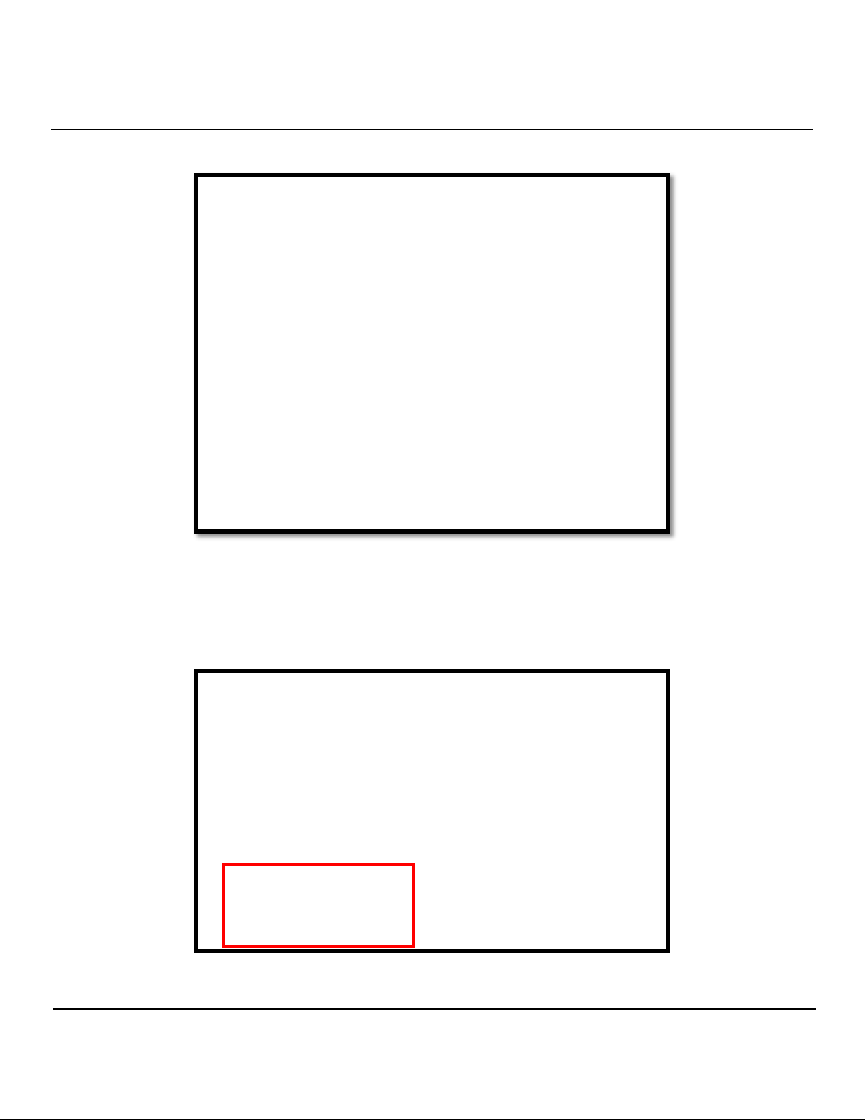
4.2.5 Activate the mRDS by pressing the “Start” button on the bottom-left corner of the
Touchscreen Controller “Default Screen” (Figure 1).
FIGURE 1
AeroClave mRDS Operator Manual
Released January 8, 2016 Page 8
Use or disclosure of data contained on this sheet is subject to the restriction on the cover page of this User’s Manual.
4.2.6 Upon initial activation a safety prompt will appear (Figure 2).
4.2.7 Once criteria on the safety prompt have been met, tap the “green” start button to begin the
decontamination process (Figure 3).
FIGURE 2
FIGURE 3
AeroClave mRDS Operator Manual
Released January 8, 2016 Page 9
Use or disclosure of data contained on this sheet is subject to the restriction on the cover page of this User’s Manual.
4.3 Decontamination Cycle Operation
4.3.1 The following section describes how to monitor a decontamination cycle using the
touchscreen controller, which is located in proximity to the treatment area.
4.3.2 These steps describe the process and screens regarding operation DURING a
decontamination cycle.
4.3.3 The touchscreen controller is used to monitor and control the mRDS through all phases of
its operation.
4.3.4 Activate the mRDS by following the steps described in Section 4.2.
4.3.5 Prior to the start of the decontamination process , the system will cycle through an initial
warning stage.
4.3.6 This “Warning Countdown” stage precedes all operation stages and allows for additional
time to ensure all safety criteria have been met (Figure 4).
4.3.7 After the “Warning Countdown” stage, the decontamination process will begin.
FIGURE 4

AeroClave mRDS Operator Manual
Released January 8, 2016 Page 10
Use or disclosure of data contained on this sheet is subject to the restriction on the cover page of this User’s Manual.
4.3.8 The first stage of the decontamination process is the “Injection” stage. This is when the
disinfectant solution is atomized into the treatment area. (Figure 5).
4.3.9 The second stage of the decontamination process is the 10 minute “Dwell” stage. This is
when the disinfectant solution achieves the necessary surface contact time (Figure 6).
FIGURE 5
FIGURE 6
Dwell

AeroClave mRDS Operator Manual
Released January 8, 2016 Page 11
Use or disclosure of data contained on this sheet is subject to the restriction on the cover page of this User’s Manual.
4.3.10 The third and final stage is the “Aeration” stage. This is when ventilation of the treatment
area occurs to return the environment to normal operating conditions. During this stage,
normal operation of HVAC, exhaust, or ventilation can resume (Figure 7).
4.3.11 The Touchscreen Controller will switch from red to yellow to green as the “Aeration” stage
and the decontamination process finishes (Figure 8).
FIGURE 8
Aeration
Aeration
FIGURE 7
Aeration

AeroClave mRDS Operator Manual
Released January 8, 2016 Page 12
Use or disclosure of data contained on this sheet is subject to the restriction on the cover page of this User’s Manual.
4.3.12 Once the Touchscreen Controller has returned to the green “SAFE TO ENTER” screen AND
the air in the treatment area is clear, it is safe to resume normal operation and habitation of the
treatment area (Figure 9).
FIGURE 9

AeroClave mRDS Operator Manual
Released January 8, 2016 Page 13
Use or disclosure of data contained on this sheet is subject to the restriction on the cover page of this User’s Manual.
4.4 Emergency Stop Operation
4.4.1 The following section describes mRDS’ emergency stop operation.
4.4.2 These steps describe the process and screens regarding emergency stop operation DURING
a decontamination cycle.
4.4.3 The mRDS emergency stop procedure initiates a total shutdown of the system.
4.4.4 To initiate an emergency stop, simply press the red “Emergency Stop” bar at the bottom of
the Touchscreen Controller (Figure 10).
4.4.5 Once an emergency stop has been initiated, determine the reason why emergency stop
occurred and attempt to resolve the situation.
FIGURE 10

AeroClave mRDS Operator Manual
Released January 8, 2016 Page 14
Use or disclosure of data contained on this sheet is subject to the restriction on the cover page of this User’s Manual.
4.4.6 Once the situation has been resolved, reset the mRDS by pressing the “Reset” button on the
bottom left corner of the Touchscreen Controller prior to operation (Figure 11).
4.4.7 Upon pressing “Reset”, the Touchscreen Controller will return to the green “SAFE TO
ENTER” screen. At this point, operation of the mRDS can resume (Figure 12).
FIGURE 11
FIGURE 12

AeroClave mRDS Operator Manual
Released January 8, 2016 Page 15
Use or disclosure of data contained on this sheet is subject to the restriction on the cover page of this User’s Manual.
5.0 PREVENTATIVE MAINTENANCE
The mRDS must be flushed with distilled water on a monthly basis to ensure proper operation and a long
life. The length of time necessary to fully flush the system is dependent on the number of nozzles installed
inside the treatment area. After flushing the system, you should re-prime the system by switching the reservoir
back to Vital-Oxide and running for the prescribed time. Please refer to Table 1 for Flush and Re-Prime
times. You must follow the following steps flush the system correctly.
5.1 General Guidelines
5.1.1 Flush mRDS completely on a monthly basis.
5.1.2 Use only distilled or deionized water when flushing the mRDS.
5.1.3 After the maintenance flush, re-prime the mRDS with disinfectant
5.2 Maintenance Steps
5.2.1 Replace on-board operating reservoir with the provided maintenance reservoir.
5.2.2 Ensure that the maintenance reservoir is filled with distilled or deionized water only.
5.2.2 Start the operation of the mRDS unit like normal.
5.2.3 Use the Touchscreen Controller as an E-stop to stop the unit after it has run for the
prescribed Flush Time (see Table 1).
5.2.4 Reset the system.
5.2.5 Replace the on-board operating reservoir filled with Vital-Oxide
5.2.6 Start the operation of the mRDS unit like normal.
5.2.7 Use the Touchscreen Controller as an E-stop to stop the unit after it has run for the prescribed
Re-Prime Time (see Table 1).
5.2.8 Reset the system.
Table 1
System Flush Time Re-Prime Time
mRDS 4 minutes 3 minutes

AeroClave mRDS Operator Manual
Released January 8, 2016 Page 16
Use or disclosure of data contained on this sheet is subject to the restriction on the cover page of this User’s Manual.
6.0 MISCELLANEOUS
6.1 Configuration
6.1.1 The length of time associated with each stage of the decontamination process can be
adjusted, if necessary, by accessing the “Configuration” screen.
NOTE: Do NOT adjust these values without fir st consulting with author ized
AeroClave personnel.
6.1.2 To access the “Configuration” screen, press the “Install” button on the bottom right corner
of the Touchscreen Controller (Figure 13).
6.1.3 Tap the white dialog boxes to input the time for each stage of the process (Figure 14).
FIGURE 13
FIGURE 14
Table of contents
Other AeroClave Cleaning Equipment manuals

Popular Cleaning Equipment manuals by other brands


LEHMANN
LEHMANN QLEEN PROFI II User information

Kärcher
Kärcher SE 4001 instruction manual

Black & Decker
Black & Decker BEPW1300L Original instructions

Livington
Livington BladeStar Instructions for use

Makita
Makita DX01 instruction manual

ThermaCor
ThermaCor Thermax Therminator DV12 Owner's/operator's manual

Build with Robots
Build with Robots Breezy Blue Response user manual

Dremel
Dremel PC10-05 Operating/safety instructions

Nilfisk-Advance
Nilfisk-Advance SC UNO 4M Instructions for use

IPC
IPC SKID FUEGO LS 2675 E instruction manual

ECOVACS
ECOVACS DEX11 instruction manual

RS4
RS4 407H-16 Installation & maintenance instructions