Images are for illustrative purposes.
We reserve the right to make changes. 5
®
RDM-31-0222
NORDcanopy |OZ 3.0 Installation Guide
3. Prepare the Ozone Modules
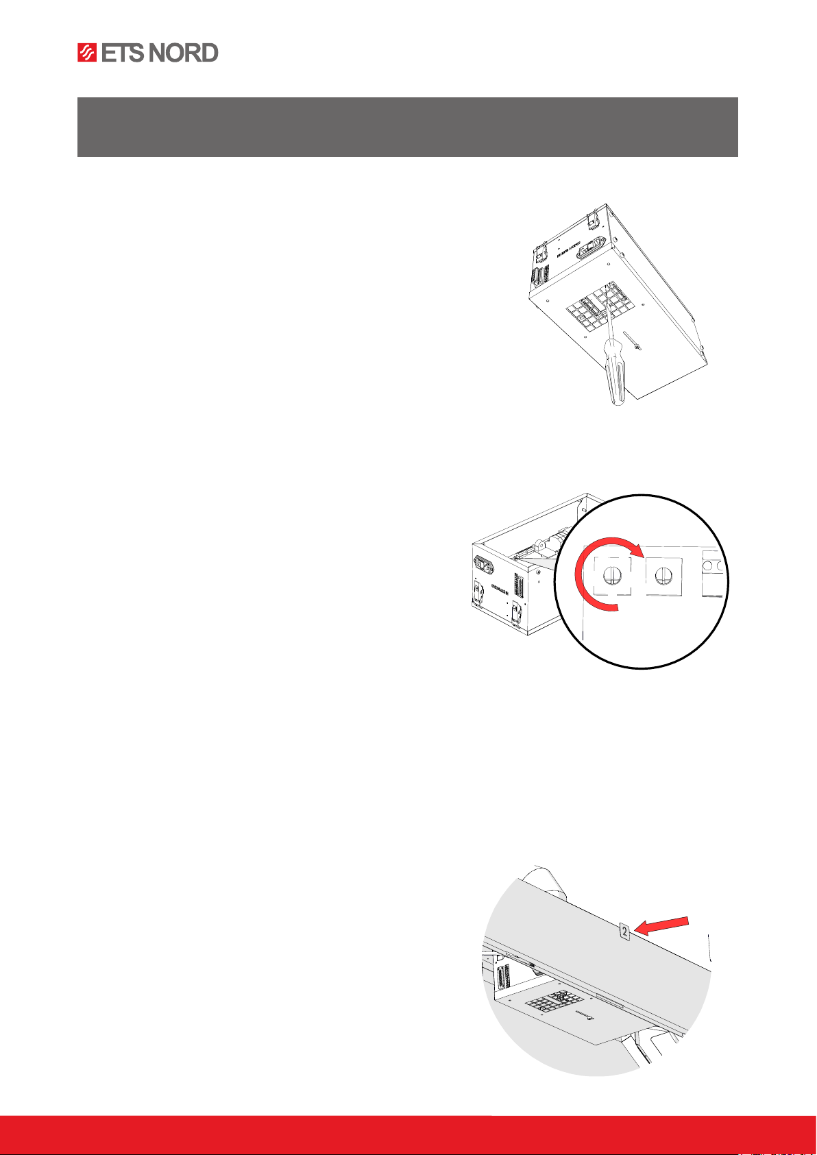
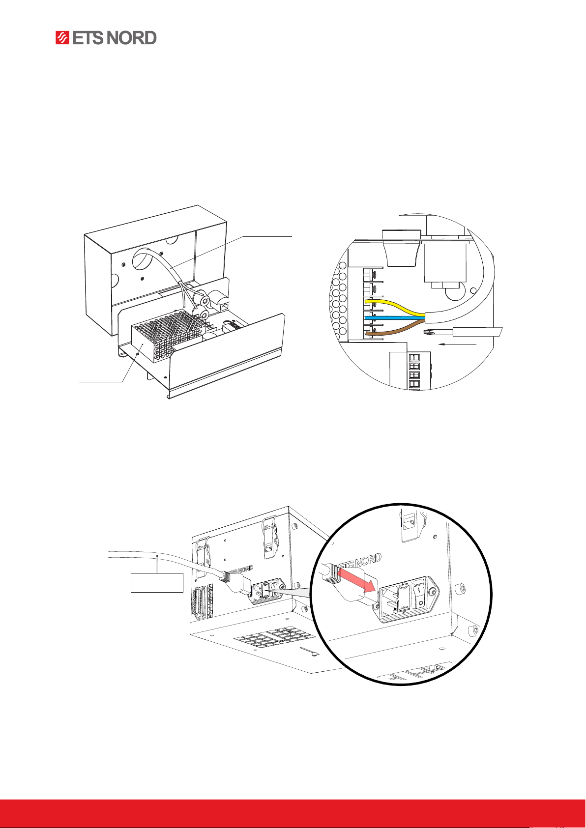
3.1 Set the device addresses
Each OZ module must be set to a unique device address
A flashlight and a long, narrow 2mm flat-head screwdriver will be
needed for this procedure. The unit will not need to be opened as the
necessary rotary switches can be accessed through the air intake at
the bottom of the chassis as shown in the picture.
NOTE! Before installing any Ozone Module, please ensure that
its air intake adjustment plate, if installed, is adjusted for full
airflow through the perforated holes and the fixing screw is
tightened.
Set the device address for each Ozone Module by turning the
rotary address switches located on the upper left corner of the
air intake grid. The address is set using the switches marked
“1x” and “10x”. The “1x” switch is positioned nearest the corner
of the circuit board.
Example:
Ozone Module one (Adress 1):
Switch 1x = 1
Switch 10x = 0
Ozone Module thirteen (Adress 13):
Switch 1x = 3
Switch 10x = 1
Addresses should be set in ascending order begin with the Ozone Module closest to the Control Panel and
increasing by one for each sequential module. The first connected Ozone Module should have the address 1.
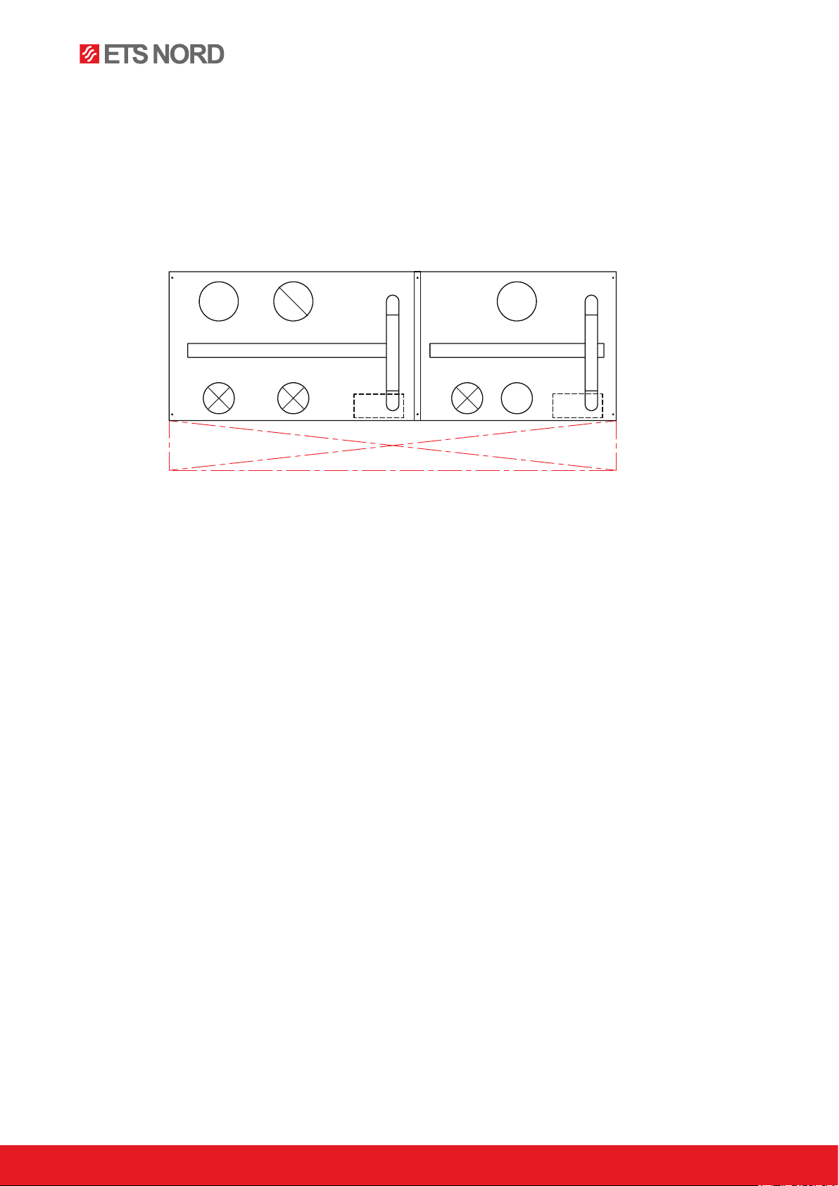
Mark the installation positions of each Ozone Module
The location of each Ozone Module shall be marked by placing an identification label on the upper front panel
of the canopy. The label should match the device address of
the module installed beneath it. You will find a sheet of labels
in the Control Panel package.
1x
6
10x
8
4
2
0
Do not attach the sticker to the perforated
area of the canopy.
NOTE! Installation may only be carried out by ETS NORD trained and authorized persons in
accordance with local, regional, national standards and regulations.