INSTALLATION GUIDE
KALE FANS
www.kalefans.net
2019
BOREAS series
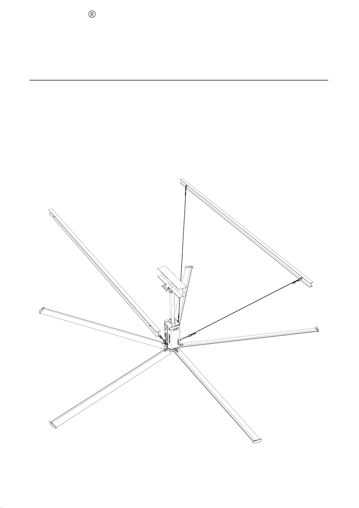
BOREAS series Big Energy-Saving fan is a super fan with a diameter of 7.3m! Kale Airfoil Blades, which are streamlined,
are developed with the advanced technologies and the principle of aerodynamics. With a power of 1.5KW or less, the
blade is able to drive a mass of air and makes the natural wind system with ultra-large area, which leads to the double
function of ventilation and temperature reduction. Compared to the traditional HVAC conditioner and small high-speed
air blower, the fan is superior in application, and that makes it immaculate for the large space to ventilate and reduce
temperature. BOREAS Series fan is a primary product for KALEFANS and its coverage can be up to 1600 sq metres. The
fans are mainly applied in large space such as the plant, logistics & warehouse, supermarket and farm, etc.
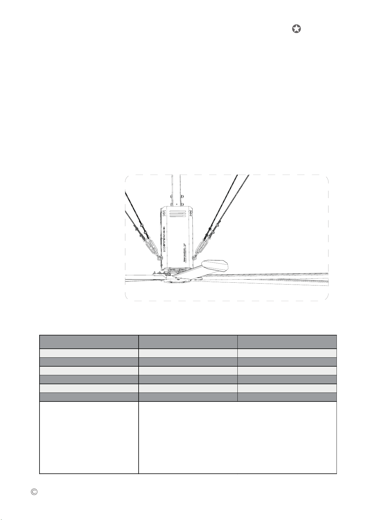
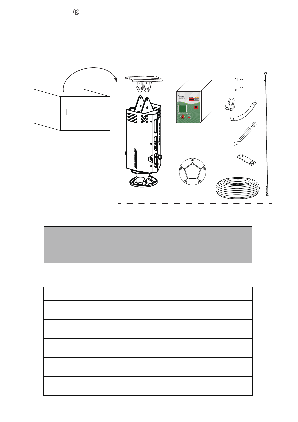
1.1 Product specification table
-3-
1. Production series introduction
技术规格 Technical Specifications 20ft(6.1m)24ft(7.3m)
型号Model D4BAA61 D4BAA73
满载风量 Air disp.@Max speed
12000m³/min 13050m³/min
最大转速 Maximum speed 70RPM 60RPM
风扇主体重量 Fan weight 97kg 110kg
电机功率 Moto size 1.5Kw 1.5Kw
满载电流 Full load amps 3.5Amps/380V 5.7Amps/220V 3.5Amps/380V 5.7Amps/220V
1、重量计算:产品重量不包含控制箱,
顶部连接构件等。
2、尺寸:以上所列产品尺寸为标准品,
其他规格尺寸可定制。
3、噪音:声级计距离电机1m,电磁噪音
40dB(A)以下。
4、包装:标准木箱包装。
5、输入电源:三相380V/220V,单相
220V可选。
1, Weight: the weight does'nt contain control box, top connection parts
etc.
2, Size: the above-mentioned product size is standard, other size can be
customized.
3, Noise: sound level measured a distance of 1 m from the motor,
electromagnetic noise is less than 40 db(A).
4, Packing: Export standard crates.
5, Input power: 380 VAC, 3P, 50/60 Hz.220 VAC, 3P, 50/60 Hz.220 VAC, 1P,
50/60 Hz.