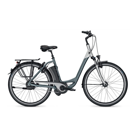
Kalkhoff Derby User manual

Belgium: Derby Cycle Werke GmbH, Siemensstr. 1-3, D-49661 Cloppenburg, Phone: +49-4471966101
France: Derby Cycle Werke GmbH, Siemensstr. 1-3, D-49661 Cloppenburg, Phone: +49-4471966101
Great Britain: 50Cycles Ltd., Unit M Littlemoor Lane, GB-Loughborough LE11 1SF, Phone: +44-1509 266656
Italy: Bike Evolution, Rigaste S. Zeno 39/B, I-37123 Verona, Phone: +39-045592410
Latvia: Laterns Ltd., Brivibas 353/16, LV-1000 Riga, Phone: +371-9848860
Lithuania: Meibalt, Svitrigailos 5, LT-2000 Vilnius, Phone: +370-52651259
Netherlands: Derby Cycle Werke GmbH, Siemensstr. 1-3, D-49661 Cloppenburg, Phone: +49-4471966101
Romania: S.c. SportBikeCenter. S.r.l, St. Penes Carcanul 3-5, RO-300124 Timisoara, Phone: +40-256220023
Slovakia: AGF Invest s.r.o., Hlinikova 365/39, SK-95201 Vrable, Phone: +421-262859549
Spain: Clean Laguna S.L., Urbanisation Sant Jordi da Alfama, E-43860 Ametlla de Mar, Phone: +34-977486160
Kalkhoff bikes
Derby Cycle Werke GmbH
Siemensstraße 1-3
49661 Cloppenburg
Tel. +49 (4471) 966-0
Fax +49 (4471) 966-44845
E-Mail: [email protected]
www.kalkhoff-bikes.com 1973K0110002
Instruction manual
Guide d’utilisation
Instrucciones de uso
Handleiding
KALKHOFF - Instruction manual - Guide d‘utilisation - Handleiding - Instrucciones de uso

Foreword
Your bicycle was delivered to you fully assembled. In case any bicycle parts are not
assembled, please contact your bicycle dealer.
These instructions help you in the
●appropriate,
●safe and
●advantageous
Use of your bicycle.
We assume that users already have general knowledge regarding
the handling of bicycles.
Every person who
●uses,
●cleans,
●maintains or
●disposes of this bicycle
must be fully acquainted with the entire contents of this instruction manual.
Layout features
Various elements of this instruction manual are provided with special symbols, which
enable you to easily distinguish between normal text,
●lists or
➢actions to be taken or
important additional information or particular details regarding the use
of the bicycle.
Contents
Safety advice 4
Fundamental safety advice 4
Appropriate use as intended 5
Assembling the pedals 6
Pedal types 6
Before each use 7
Use of the quick release 7
Adjusting the saddle 7
Determining the correct saddle height 8
Adjusting the saddle height 8
Adjusting the saddle tilt 8
Suspension seat post 9
Adjusting the handlebar 9
Determining the correct handlebar height 9
Adjustment of the handlebar height for a conventional handlebar stem 9
Adjustment of the A-Head system handlebar height 10
Aligning the handlebar to the front wheel 10
Adjustment of the handlebar height for an adjustable handlebar stem 10
Checking the headset 10
Checking the bottom bracket / inner bearing 10
Using the gear shifter 11
Using the multispeed chain gear shifter 11
Shift lever operation 11
Racing shift lever 12
Standard shift lever 14
Twistgrips 15
Derailleur 15
Fine adjustment of the derailleur / troubleshooting 15
Chain guide 16
Fine adjustment of the chain guide 16
Using the multispeed hub gear shifter with and without a coaster brake 16
Shimano hub gear shifter 17
Shimano 3-speed shift lever 17
Shimano 7/8-speed shift lever 18
Dismounting and mounting the rear wheel with Shimano hub 18
Removing the rear wheel 18
Refitting the rear wheel 18
SRAM hub gear shifter 22
SRAM 3-speed 22
SRAM 5(7)-speed brake gear hub 23
Bicycle chain maintenance 24
Brakes, brake levers and braking systems 24
Brake levers 26
Wheel rim brakes 26
Disc brakes 27
Hydraulic disc brakes 27
Drum brakes and roller brakes 28
SRAM drum brakes 29
SHIMANO drum brakes 30
3
english
françaisnederlands
español
DCW BedienA_GB UNI.qxd 24.10.2007 12:50 Uhr Seite 3

4
Frame 32
Forks 32
Checking the wheels 34
Checking the tyres and inner tubes 34
Tyres 34
Inner tubes 35
Repairing a puncture 35
Operating the lighting components 37
Dynamo 37
Failure of the lighting system 38
Carrier 38
Mudguards 38
Bicycle stand 39
Selecting accessories and equipment 39
Handling carbon components 40
Care and maintenance of the bicycle 41
Care 41
Consumable parts 42
Regular inspection 43
Inspection schedule 44
Technical data44
Total permissible weight of the bicycle 44
Permissible carrier load 44
Tightening torques of screws, nuts and bolts 45
Tightening torques of Shimano components 45
Tyres and tyre pressures 46
Warranty conditions 46
Safety advice
Read all warnings and notices in this operating manual completely before using the
bicycle. Always store the operating manual near to the bicycle so that it is available at
all times.
If you pass on or sell your bicycle to others, please also hand out this operating manu-
al to them.
Fundamental safety advice
Personal safety measures
●Always use a suitable bicycle helmet.
●Wear light coloured clothing or clothing with reflective elements, so that other
road users can see you.
●Wear shoes with rigid and, as far as possible, non-slip soles.
●Wear tight-fitting trousers or use bicycle clips.
●Always wear suitable protective clothing when riding, such as solid shoes
and a bicycle helmet.
Bicycle safety
●Observe the maximum load of the relevant bicycle type, otherwise important
operational parts could break or fail.
●Have damaged or bent parts replaced before riding the bicycle again,
otherwise important operational parts could fail.
●Observe the maximum load of the carrier. It is marked on the carrier
(see chapter “permissible carrier load“, page 44).
●Have maintenance and repairs carried out by a dealer.
Comply with maintenance intervals (see page 43).
●If you make any technical changes to your bicycle, you should observe
the national traffic regulations and valid standards.
●Electrical parts of your bicycle may only be replaced by type-tested parts.
●During adverse light conditions such as
●fog ●rain ●dusk ●darkness
you should only ride with sufficient lighting.
DCW BedienA_GB UNI.qxd 24.10.2007 12:50 Uhr Seite 4

Trekking bikes / ATBs
These bicycles may be used on public and made roads. They are also suitable for
light off-road use.
The manufacturer and dealer shall not be liable for any use of the bicycle which
goes beyond the intended use. This particularly applies to non-compliance with
safety advice and the resulting damage, for example due to:
●overload or
●improper repair of faults.
City, touring, sport, children’s and junior cycles
These bicycles may be used on public and made roads.
The manufacturer and dealer shall not be liable for any use of the bicycle which
goes beyond the intended use. This particularly applies to non-compliance with
safety advice and the resulting damage, for example due to:
●off-road use,
●overload or
●improper repair of faults.
Mountain bike (MTB)/Cross bike
These bicycles may be used off road. Do not use these bicycles to take part in
competitions. These bicycles may not be used on public roads. If you wish to use
your bike on a public road, you must comply with national regulations.
The manufacturer and dealer shall not be liable for any use of the bicycle which
goes beyond the intended use.
This particularly applies to non-compliance with safety advice and the resulting
damage, for example due to:
●use in competitions,
●overload,
●improper repair of faults,
●riding over steps,
●jumps,
●riding through deep water or
●extreme strain outside special MTB-courses.
5
Road traffic safety
●Always obey the valid traffic regulations.
●Never ride hands-free. This can lead to serious accidents.
●Remember that children under eight years of age must ride on the pavement.
Children aged eight to ten may ride on the pavement.
If children have to cross the road, they must dismount from the bicycle.
●When the road is wet, adjust your riding style accordingly.
Ride more slowly and brake earlier, as the braking distance will be
noticeably longer.
●Adjust your speed according to the terrain and your ability.
●Don’t listen to music via headphones whilst riding your bike.
●Don’t use a mobile telephone whilst riding your bike.
●If you ride off-road, use only official cycle paths.
●Always be ready to brake at blind corners and when riding downhill.
Appropriate use as intended
General
Bicycles are intended as a means of transport for single persons. The carrying of an
additional person on the bicycle is only permissible within the scope of national
regulations. If you wish to transport baggage, the bicycle must be suitably equipped
for this purpose. In this case, observe the loading limits for the carriers (see chapter
‘Permissible carrier load’, page 44).
Not every type of bicycle is suitable for every type of terrain. Bicycles are not designed
for extreme strains such as riding over steps or jumping.
The details given in this operating manual are valid for all types of bicycle.
Where details for individual types of bicycle differ, these are marked accordingly.
Observe the individual component manufacturers’ operating instructions, which are
supplied with your bicycle or are available online. If you still have questions after
reading the component manufacturers’ documentation, please consult your bicycle
dealer.
Appropriate use as intended also means complying with the usage, maintenance and
service conditions which are described in this operating manual.
The manufacturer and dealer shall not be liable for any use of the bicycle which goes
beyond the intended use.
english
françaisnederlands
español

DCW BedienA_GB UNI.qxd 24.10.2007 12:50 Uhr Seite 5

6
Racing cycles / fitness bikes
If racing cycles are to be used on public roads, the national regulations must be com-
plied with.
The manufacturer and dealer shall not be liable for any use of the bicycle which goes
beyond the intended use. This particularly applies to non-compliance with safety advice
and the resulting damage, for example due to:
●off-road use,
●overload,
●improper repair of faults or
●competitions.
Assembling the pedals
Tighten all screws to the specified torque, otherwise the screws could break
off and parts may become loose. (see chapter ‘Tightening torques of screws, nuts
and bolts’, page 45).
If the pedals are placed in position at an angle or screwed in crookedly,
the thread in the crank arm may be destroyed.
The left pedal (”L“) has a left-hand thread, the right pedal (”R“) has a
right-hand thread.
Racing cycles or mountain bikes may be delivered without pedals.
If you wish to mount the pedals of your racing cycle or mountain bike yourself,
proceed as follows:
➢Paint both pedal threads with a medium-strength thread sealant (glue).
Thread sealant prevents screws from working loose on their own.
Thread sealant is available from hardware stores.
➢Screw the left pedal in an anticlockwise direction into the left pedal crank.
➢Screw the right pedal in a clockwise direction into the right pedal
crank (on the chain side).
➢Tighten both pedals using a size 15 spanner.
Pedal types
Use MTB, racing and system pedals only with the matching shoes.
You might slip off the pedals with other shoes.
The use of MTB or racing pedals may lead to serious falls if the user is not
experienced.
If you use system pedals, at first practise fastening and unfastening the shoes to
and from the pedals whilst standing still. Never practice in traffic.
Read the pedal and shoe manufacturers’ instructions.
1 MTB pedals
2 Touring or sport pedals
3 System pedals
1
2
3
DCW BedienA_GB UNI.qxd 24.10.2007 12:50 Uhr Seite 6

To open the quick release, proceed as follows:
➢Tilt the tensioning lever, so that the word OPEN is readable.
➢Open the quick release as far as it will go.
➢To loosen the quick release, turn the locking nut in an anticlockwise direction.
To close the quick release, proceed as follows:
➢Adjust the locking tension using the locking nut.
➢If the quick release is too loose, open it again and turn the locking
nut in a clockwise direction.
If the quick release is still too easy to close, repeat the last step.
➢If the quick release is too difficult to close, turn the locking nut in an
anticlockwise direction.
➢Tilt the tensioning lever away from the OPEN position, so that the
word CLOSE is readable.
Adjusting the saddle
The seat position is crucial to your comfort and cycling efficiency.
Do not remove the seat post or the saddle clamp.
The manufacturer accepts no liability for damage or accidents.
Tighten all screws to the specified torque, otherwise the screws could break off and
parts may become loose. (see chapter ‘Tightening torques of screws, nuts and bolts’,
page 45).
You should only carry out work on your bicycle with suitable tools and
sufficient knowledge. Have complicated repairs or work related to safety done
by a dealer.
Adjust the bicycle saddle and handlebar to suit your requirements.
7
Before each use
Despite taking great care during production and final checking, parts
may work loose or their functionality may alter during transport.
➢For this reason, the following items must be checked before each use:
●tightness of the quick releases,
●tightness of all screws, nuts and pedals,
●adjustment and tightness of suspension parts
●adjustment and function of the brakes
●tightness of pipes and connectors if hydraulic brakes are being used,
●fastening of the saddle support and the handlebar stem,
●minimum insertion depth of the seat post and the handlebar stem,
●lighting function,
●gear shift function,
●proper fixing of the wheels and
●sufficient tyre tread depth and correct tyre pressure.
Use of the quick release
All quick releases must be fastened tightly before riding.
Check that all quick releases are correctly seated if the bicycle has been left
unattended for a while.
When tightening the quick release, so much force is required that you will need to use
the ball of your hand, otherwise the quick release could loosen itself.
A quick release is made up of two
operating elements:
1 Tensioning lever
2 Locking nuts 1
english
françaisnederlands
español
DCW BedienA_GB UNI.qxd 24.10.2007 12:50 Uhr Seite 7

8
Determining the correct saddle height
➢Sit on the bicycle saddle.
➢Try to reach the pedal at its lowest position
with your heel.
Your knee should be almost completely
straight at this point.
➢Place the ball of your foot in the centre
of the pedal.
If your knee is now slightly bent, the saddle
height is correctly adjusted.
Adjusting the saddle height
Never pull the seat post out of the seat tube beyond the maximum or stop
mark or the height of the middle of the top tube, (in the case of bicycle frames
without top tube, beyond the middle of the seat brace). The bottom end of the seat
post must be at least at the same height as the top tube, otherwise you may injure
yourself and damage the seat post.
If the saddle of a mountain bike with full suspension (MTB-Full-Suspension) is
adjusted to its lowest point, the seat post may protrude a maximum of 20 mm from
the seat tube at the bottom end, otherwise the real wheel rocker arm will collide
with the seat post when the damper is compressed.
The minimum insertion depth is marked. If
the saddle support has no marking, the mini-
mum insertion depth must be 7.5 cm. In the
case of frames with longer seat tubes, which pro-
trude beyond the upper tube, the minimum
insertion depth is 10 cm.
To adjust the saddle height, proceed as follows:
➢Loosen the saddle locking screw by turning
it anticlockwise using an allen key or by
opening the quick release (see chapter ‘Use
of the quick release’, page 7).
➢Pull the saddle out of the seat tube until
the required height is reached.
➢Lock the saddle locking screw by turning it
clockwise using an allen key or by closing
the quick release.
➢Check once again that the saddle height is
correct (see chapter ‘Determining the
correct saddle height’, left).
Adjusting the saddle tilt
Adjust your saddle so that it is as level as possible, or slightly tilted to the rear.
Determine the most comfortable seating position by making a longer cycling trip.
If necessary, adjust the saddle tilt by proceeding as follows:
➢To loosen the locking screw, turn it in an
anticlockwise direction.
➢Tip the saddle until the required tilt is reached.
➢To tighten the locking screw, turn it in a
clockwise direction. (for tightening torque,
see page 45).
Saddle locking screw
Quick release
Observe
the stop mark!
DCW BedienA_GB UNI.qxd 24.10.2007 12:50 Uhr Seite 8

In the case of a saddle with a collar clamp, the
locking screw is located at the side. If necessary,
adjust the saddle tilt by proceeding as follows:
➢To loosen the locking screw, turn it in an
anticlockwise direction. It may be necessary to
hold the nut located on the other side using a
second spanner.
➢Tip the saddle until the required tilt is reached.
➢To tighten the locking screw, turn it in a
clockwise direction. It may be necessary to hold the nut located on the
other side using a second spanner (for tightening torque, see page 45).
Suspension seat post
Suspension seat posts compensate for mild shocks and
road unevenness. This reduces stress on the spine during
cycling.
If the spring elements of the seat post need to be
adjusted, consult your dealer.
Adjusting the handlebar
Tighten all screws to the specified torque, otherwise the screws could break
off and parts may become loose (see chapter ‘Tightening torques of screws, nuts
and bolts’, page 45).
Determining the correct handlebar height
By altering the handlebar height, you can determine the seating position on the
bicycle. The seating position will be changed by a height difference between the
handlebar and the saddle.
The lower you adjust the handlebar, the further you will have to lean forward.
This results in an increase in the load on wrists, arms and upper body.
The higher you adjust the handlebar, the more upright you will have to sit. This results
in an increase of the load on the spine.
Determine the optimum handlebar height for your body height as follows:
➢Sit on the bicycle saddle.
➢If necessary, ask someone to hold the bicycle.
➢Bend forward towards the handlebar until you reach a position which is
comfortable for your back.
➢Stretch your arms out towards the handlebar.
➢Note the approximate height of your hands, so that you can adjust the
handlebar to this height.
Adjustment of the handlebar height for conventional handlebars
Never pull the handlebar stem out beyond the maximum or stop mark
on the stem tube. Insert the handlebar stem to a minimum depth of 65 mm
in the steering tube, otherwise the handlebar stem can slip down.
To loosen the stem shaft in the steering tube, proceed as follows:
➢Release the stem spindle in order to loosen the handlebar stem.
Turn it two to three turns in an anticlockwise direction using an allen key.
➢Clamp the front wheel between your knees to prevent the bicycle fork
from moving when the stem shaft is loosened.
➢Turn the stem shaft backwards and forwards.
➢If this is not possible, tap the stem spindle lightly with a plastic
hammer from above until the locking screw inside the steering tube loosens
itself.
Having loosened the stem shaft, proceed as follows:
➢Push the handlebar stem to the required height.
➢Adjust the handlebar so that the handlebar
stem is at a right-angle to the bicycle frame.
➢To tighten the stem shaft again, turn the stem
spindle with an allen key in a clockwise direction
(for tightening torque, see page 45).
9
english
françaisnederlands
español
DCW BedienA_GB UNI.qxd 24.10.2007 12:50 Uhr Seite 9

Adjustment of the A-Head system handlebar height
Stems such as the one illustrated here are called A-Head stems. If this system is fitted,
it is compulsory to have the handlebar height adjusted by a dealer.
Aligning the handlebar to the front wheel
To align the handlebar to the front wheel, proceed as follows:
➢Loosen the allen screw at the front side of the
stem by turning it in an anticlockwise direction
using an allen key.
➢Turn the handlebar to the desired position.
Ensure that the handlebar is clamped exactly at
the centre of the stem.
➢Tighten the allen screw in a clockwise direction
using an allen key (for tightening torque, see
page 45).
Adjustment of the handlebar height for an adjustable handlebar stem
On some types of handlebar stems, the tilt of the handlebar is variable.
The locking screws for the handlebar tilt adjustment can be found at the side of the
joint or on the top or the underside of the stem. There are also
models with additional retaining
catches or adjustment screws.
➢Loosen the locking screw
two to three turns in an
anticlockwise direction
using an allen key.
If you own a model with additional latching gear, proceed as follows:
➢To loosen the serration of the latching gear, turn the locking screw further in an
anticlockwise direction if necessary.
If you own a model with integrated retaining catches, proceed as follows:
➢Remove the retaining catch screws if necessary.
The retaining catch screws are located on the underside of the stem
on many stem models.
➢Adjust the handlebar stem to the desired height
➢Tip the handlebar stem to the desired tilt.
To tighten the handlebar stem, proceed as follows:
➢In the case of models with integrated retaining catch, carefully tighten the
retaining catch screw in a clockwise direction.
➢The retaining catch must thereby grip the serration.
Tighten the locking screw in a clockwise direction using an allen key
(for tightening torque, see page 45).
Checking the headset
If the headset is improperly adjusted or tightened too hard, breakage
may occur, therefore always consult a dealer.
If you ride with a loose headset, damage may occur to the bearing casing
or the forks.
The headset forms the bearing of the
bicycle forks in the frame. A properly
adjusted headset can be easily tur-
ned. However, there should be no
play.
Shocks from the road place a great strain on the headset. It can be become loose
or misadjusted. Have the play and the ease of movement of the headset checked
regularly by a dealer (for intervals, see page 44).
Checking the bottom bracket
Chain sprockets are consumable parts. Their service lifetime depends on various
factors such as:
●Maintenance and care,
●type and duration of use and
●the distance travelled.
10
Allen screws
Adjustment
screw
DCW BedienA_GB UNI.qxd 24.10.2007 12:50 Uhr Seite 10

The crank arms must be seated tightly, otherwise the crank assembly may become
damaged.
➢Since the crank arms can become loose, check the tightness of the
bottom bracket regularly.
➢To check that the crank arms are seated tightly on the axles, shake
them regularly.
➢If any play is found in the crank arms, have the bicycle checked and the
arms tightened by a dealer.
Using the gear shifter
Using the multispeed chain gear shifter
This operating manual describes the typical, conventional gear shift components of
an MTB, ATB, crossbike or racing cycle. In the case of differing components, refer to
the special information or attached manuals. If anything is unclear to you, consult
your bicycle dealer in the case of questions regarding assembly, maintenance and
operation.
Loose, worn, damaged or incorrectly adjusted gear shift components
represent a risk of injury to the rider.
Have the chain gear shifter adjusted by a dealer!
● If the chain jumps off the chain sprockets, or
● if abnormal noises are heard, or
● if gear shifting does not work correctly, or
● if the chain guide, derailleur or other gear shift components are loose,
damaged or bent, or
● if the chain links are loose or worn, consult your dealer to have repairs
carried out.
The bicycle chain may not sit simultaneously on the smallest chain
sprocket at the front and the small outer sprocket at the rear, nor may it sit
simultaneously on the largest chain sprocket at the front and the large inner
sprocket at the rear, otherwise the chain may become disengaged.
Never pedal backwards when shifting gear, otherwise the gear shifter may be
damaged. Be careful when making adjustments to the gear shifter.
Due to incorrect adjustments, the chain may jump off the sprocket which may
lead to a fall. If you are not sure, have the work done by a dealer.
Do not ride without the spoke protector, otherwise the bicycle chain
or the gear shifter mechanism could get between the sprockets and the spokes.
Change to the lowest gear (largest rear sprocket) very carefully using the gear
shift, otherwise the changer mechanism could come into contact with the
spokes and damage them.
Shift lever operation
There are various types of gear shit levers.
The commonest types are described below.
Racing shift lever
The Shimano brake shift lever may exist in two versions.
All levers return to their initial positions when released. 11
Lever a
Lever a
Lever b
Lever B
Lever A Lever a
Lever b
Rear Front
Lever b
from larger to smaller
chain sprocket
Lever b
Lever a
from smaller to larger
chain sprocket
from larger to smaller
chain sprocket
from smaller to larger
chain sprocket
Lever a
Lever B
Rear Front
Lever b
Lever aLever A
Lever A : shifting to a larger rear sprocket.
Lever B : shifting to a smaller rear sprocket.
Lever a : shifting to a larger chain sprocket.
Lever b : shifting to a smaller chain sprocket.
english
françaisnederlands
español
DCW BedienA_GB UNI.qxd 24.10.2007 12:50 Uhr Seite 11

Actuating the chain guide lever
●Lever A: shifting to a larger ●Lever B: shifting to a smaller rear
rear sprocket. Lever A latches sprocket. By pressing lever B once,
in positions 1, 2 and 3. gear is shifted to the next smaller
rear sprocket.
12
Actuating the derailleur lever (standard)
Lever ‘b’ moves with lever ‘a’ when it is actuated. However, the exertion of pressure on
lever ‘b’ must be avoided. Correspondingly, the exertion of pressure on lever ‘a’ must be
avoided when actuating lever ‘b’. The simultaneous actuation of both levers results in
no gear shift.
Actuating the derailleur lever with trimming
(noise minimisation) optional
Shift procedure
Lever a Initial position
Lever a
Complete chain
shift lever stroke Stroke actually
performed
Lever a: shifting to a larger chain sprocket.
If the lever movement does not produce a
complete change of chain sprocket, the lever
must be moved again by amount (X’) in
order to execute the missing lever movement
distance (X) and thus the gear shift.
Lever b Initial position
Lever b
Complete
chain
shift lever
stroke
Lever b: shifting from the largest to the middle chain sprocket.
When shifting using lever b, an initial click
stop marks the start of trimming (noise
prevention mechanism) and a second,
stronger click stop marks the complete
chain sprocket shift. After trimming,
the next press concludes the shift
sequence.
Click position
Click position
Lever B moves with lever A when it is actuated;
however, the exertion of pressure on lever B must
be avoided. Correspondingly, the exertion of
pressure on lever A must be avoided when
actuating lever B. The simultaneous actuation of
both levers results in no gear shift.
Lever A
1: Shifting by one gear to the
next larger rear sprocket.
Example: Shifting from
3rd to 4th gear.
2: Shifting by two gears to
a larger rear sprocket.
Example: Shifting from
3rd to 5th gear.
3: Shifting by three gears to
a larger rear sprocket.
Example: Shifting from
3rd to 6th gear.
Example: Shifting from
4th to 3rd gear.
Initial position
Lever A
3rd click position
2nd click position
1st click position
4 3
35
3
6
Lever B
Initial position
Lever B
34
Operating advice
Lever b
Initial position
Lever b
Complete derailleur
lever stroke
Lever b: shifting from the middle to the smallest chain sprocket
Click position
Click position
DCW BedienA_GB UNI.qxd 24.10.2007 12:50 Uhr Seite 12

Trimming (noise minimisation)
Depending on the chain position after completion of shifting, the chain may rub
against the outer or inner chain guide plate and cause noises. In this case, press
lever ‘a’ or lever ‘b’ lightly in order to move the derailleur slightly so that it no
longer contacts the chain.
This adjustment is called ‘trimming’. Trimming is possible when the chain is
located on the large, middle or small chain sprocket. If noises occur, trim to one
of the following positions in order to completely eliminate the noises.
13
Chain
position Indication Trimming
Lever actuation
Derailleur movement
(contact)
Lever (a)
Chain
position
outer chain guide
plate
derailleur movement
before trimming
after trimming
Trimming
Chain
Chain touches
outer chain guide
plate
large chain sprocket
smaller
rear sprockets
smaller
rear sprockets
smaller
rear sprockets
middle chain sprocket
small chain sprocket
Chain
position
(contact)
Lever (b)
Chain
inner chain guide
plate
Chain touches
inner chain
guide plate
large chain sprocket
middle chain sprocket
kleines Kettenblatt
larger rear sprockets
larger rear sprockets derailleur movement
Chain
position Indication Trimming
Lever actuation
Derailleur movement
before trimming
after trimming
Trimming
english
françaisnederlands
español
DCW BedienA_GB UNI.qxd 24.10.2007 12:50 Uhr Seite 13

Standard shift lever
Both levers (A) and (B) return to their initial positions after actuation.
The crank must always be turned when actuating a lever.
Actuating the derailleur shift lever
Shifting from a small to a
larger chain sprocket
By pressing lever (A) once,
the chain is shifted from
a small to a larger chain
sprocket.
Shifting from a large to a
smaller chain sprocket
By pressing lever (B) once,
the chain is shifted from
a large to a smaller chain
sprocket.
Actuating the standard chain guide lever
Shifting from a small to a larger rear sprocket.
To shift by one gear only, push the lever (A)
to position (1). To shift by two gears, push
the gear shift lever to position 2. It is
possible in this way to shift by a maximum
of three gears.
Hbl(B)
Lever (B)
Lever (A) initial position
Shifting from a large to a smaller rear
sprocket
Pressing once shifts to a smaller rear
sprocket.
When shifting using lever (B), an initial
click stop marks the start of trimming
(noise prevention mechanism) and a
second click stop marks the complete
chain sprocket shift. After trimming is
completed, the noise prevention system
does not click any more, so that only the
click positions for shifting the rear sprok-
kets remain.
If the chain is on the largest chain
sprocket and the largest rear sprocket,
the chain rubs against the derailleur,
which is noticeable from the characteristic
noises. The derailleur can be move slightly
to the inside by lightly pressing lever (B)
(to the click position) so that there are
no more noises.
Hebel (B)
1
2
14
Complete derailleur
lever stroke
Click position
Trim actuation
Click position
Lever (B)
Derailleur
movement
Chain position
Lever (A) initial position
Lever (B)
DCW BedienA_GB UNI.qxd 24.10.2007 12:50 Uhr Seite 14

If the chain falls on the crank arm
side:
If shifting from the middle to the large
chain sprocket is difficult:
If shifting from the middle to the small
chain sprocket is difficult:
If the chain rubs against the inner
chain guide when set to the largest
chain sprocket:
If the chain rubs against the outer
chain guide when set to the largest
chain sprocket:
If the middle chain sprocket is missed
out when shifting from the largest
chain sprocket:
If the chain is on the middle chain
sprocket and rubs against the inner
chain guide when shifting to the lar-
gest rear sprocket:
If the chain falls on the bottom
bracket side:
If lever actuation is difficult when
shifting from the middle to the largest
chain sprocket:
Tighten the adjustment screw for
the largest gear to the right
(approx. 1/4 turn).
Loosen off the adjustment screw
for the largest gear to the left
(approx. 1/4 turn).
Loosen off the adjustment screw
for the smallest gear to the left
(approx. 1/4 turn).
Tighten the adjustment screw for
the largest gear to the right
(approx. 1/8 turn).
Loosen off the adjustment screw
for the largest gear to the left
(approx. 1/8 turn).
Loosen off the cable sheath adjust-
ment screw to the left (1 to 2 turns).
Tighten the cable sheath adjustment
screw to the right (1 to 2 turns).
Tighten the adjustment screw for
the smallest gear to the right
(approx. 1/2 turn).
Loosen off the adjustment screw for
the largest gear to the left (approx.
1/4 turn).
Twistgrips
To shift by one gear only, turn the twistgrip forwards or backwards by one position.
Derailleur
Have the chain gear shifter maintained, adjusted or replaced by a
cycle dealer!
Fine adjustment of the derailleur / troubleshooting
Position of the cable sheath adjustment screw
This adjustment screw may be located on the frame
on racing cycles.
15
BA
Zunehmende
Pedalkraft
Zunehmende
Pedalkraft
Abnehmende
Pedalkraft
Abnehmende
Pedalkraft
Increasing
pedal force
Decreasing
pedal force
Increasing
pedal force
Decreasing
pedal force
Cable sheath adjustment screw
➢
➢
➢
➢
➢
➢
➢
➢
➢
english
françaisnederlands
español
DCW BedienA_GB UNI.qxd 24.10.2007 12:50 Uhr Seite 15

Chain guide
Have the chain gear shifter maintained, adjusted or replaced
by a cycle dealer!
Fine adjustment of the chain guide
Actuate the lever to shift the chain from the smallest rear sprocket to the second
rear sprocket. Then take up the slack and turn the crank arm.
If the chain jumps
to the third rear
sprocket:
Tighten the adjustment screw to the
right until the chain jumps back to the
second rear sprocket.
Note:
The adjustment screw may also be
located on the gear shift lever
or on the frame.
Optimum adjustment
When the slack is taken up by the gear shift lever, the chain should
rub against the third rear sprocket and make a noise if the adjust-
ment is optimal.
Release the gear shift lever in second gear and turn the crank arm.
If the chain rubs against the third rear sprocket, the adjustment
screw must be turned a little to the right so that no rubbing noises
occur.
For trouble-free SIS function, all power transmitting parts must be lubricated.
Note
If the chain is in the position shown, it may rub against the chain sprockets or derail-
leur and cause noise. In this case, you can shift the chain to the next or next-but-one
larger rear sprocket.
Cleaning:
●Use only a neutral cleaning agent for the chain. The use of alkaline or acidic
cleaning agents, such as rust remover, can damage the chain and lead to
operational faults.
●The chain sprockets and rear sprockets should be washed at periodic intervals
using a neutral cleaning agent and subsequently lubricated again.
●The chain shifter should be cleaned at periodic intervals and the moving parts
(mechanism and rollers) must be lubricated.
Using the multispeed hub gear shifter with
and without a coaster brake
This operating manual describes the typical, conventional gear shift components of a
city or trekking bike with a hub gear. In the case of differing components, refer to the
special information or attached manuals.
If anything is unclear to you, consult your bicycle dealer in the case of questions regar-
ding assembly, maintenance and operation.
16
If there are
no noises:
Loosen off the screw to the left
until the chain rubs against the
third rear sprocket.
Adjustment-
screw
Falls die Kette auf
den dritten
Zahnkranz springt
Adjustment-
screw
Falls keine
Geräusche
auftreten
BA
Kettenblätter
Zahnkränze
Adjustment screw
Chain sprockets
Rear sprockets
Gear shift lever
DCW BedienA_GB UNI.qxd 24.10.2007 12:50 Uhr Seite 16

2
3
Starting off/riding on sand
or over uneven ground/riding uphill/
carrying heavy luggage/
riding against the wind/
riding with lights switched on
Riding on level roads
Riding at high speed
…
…….......……
……….......…
Press the button to shift gear.
Increasing pedal force
3
Indicator against
Indicator
Press
Decreasing pedal force
Indicator against
START
1
START 1
Press
Revo twistgrip
Indicator
Turn the Revo twistgrip to shift to all 3 gears.
1
2
3
Starting off/riding on sand
or over uneven ground/riding uphill/
carrying heavy luggage/
riding against the wind/
riding with lights switched on
Riding on level roads
Riding at high speed
…
…
…
Increasing pedal force
3
Indicator against
Decreasing pedal force
1
Indicator against
When mounting the hub in the frame, the correct safety washers must be
inserted on both sides and the hub nuts must be tightened to the prescribed torque.
If the safety washers are inserted on one side only, or if the hub nuts are not correctly
tightened, a safety washer can fall out. This could lead to the hub axle or the gear
shift arm rotating and pulling the handlebar to one side via the gear shift cable,
which could cause a serious accident.
Brake hub:
Avoid constantly actuating the coaster brake
on long downhill sections, as the interior brake parts
can get very hot, leading to a reduction in braking
power. Be sure to use the second brake (front wheel
brake) alternately on long, steep downhill sections, so
that the rear wheel brake can cool down.
The brake drum can get very hot after prolonged
braking; the brakes should therefore not be touched for
at least 30 minutes after riding.
The gears can be shifted whilst pedalling. In rare cases noise may be caused
in the hub by the interior gear wheels and retaining catches, which is normal when
shifting gear.
If the wheel is hard to turn, the brake shoes must be replaced or the hub lubricated.
This must be carried out in a specialist workshop.
If the chain jumps off the sprockets when riding, it should first be re-tensioned. If the
adjustment range is exhausted, the sprockets and the chain must be replaced.
The coaster brake can be controlled very precisely. The full braking
power is achieved after a certain running-in period.
In order to get used to the brakes, operate the brake lever carefully at first to
acquire a feel for the coaster brake’s deceleration.
If the bicycle is left standing for a longer period, a rust film may form in the
brake drum, increasing the braking effect. Therefore, when beginning your
journey, brake gently a few times to wear off the rust film. This will help to
avoid the brakes suddenly locking.
If the hub gets too hot, this can lead to a loss of lubricant and thus to a stronger
braking effect. In this case, the brakes must be checked in a specialist workshop.
Shimano hub gear shifter
Shimano 3-speed shift lever
There are two different types of gear shift elements.
Twistgrip (Revo) Button gear shift (Rapidrise)
17
Bremstrommel
Brake drum
english
françaisnederlands
español
DCW BedienA_GB UNI.qxd 24.10.2007 12:50 Uhr Seite 17

Shimano 7/8-speed shift lever
Turn the twistgrip to shift to all 8 (7) gears.
Increasing pedal force ➢Indicator against 8 (7) Increasing pedal force ➢Indicator against 8 (7)
Decreasing pedal force ➢Indicator against 1 Decreasing pedal force ➢Indicator against 1
Dismounting and mounting the rear wheel with Shimano hub
Removing the rear wheel
Removing the Shimano 3-speed hub gear shifter unit
➢Remove the shifter unit fixing screw. Remove the shifter unit from the hub.
Pull the shifter rod out of the hub axle.
Removing the Shimano 7/8-speed hub gear shifter unit
➢Remove the cable from the shifter unit in order to remove the rear wheel from the
frame. Before doing this, set the gear shift lever to 1st gear.
➢Pull the cable sheath out of the cable sheath holder and remove the cable from
the slot in the holder.
➢Remove the cable anchor screw
from the shifter wheel.
➢If it is difficult to pull the cable sheath
out of the holder in the shifter unit,
insert a 2 mm allen key in the hole of the
shifter wheel and turn the shifter wheel
to release the cable.
➢After this, first remove the cable anchor
screw from the shifter wheel before
pulling the cable sheath out of the cable
sheath holder.
➢Loosen and remove the screws from the brake arm.
➢Remove the wheel nuts and place them aside. Remove the safety washers
from the wheel axle.
➢Pull the rear wheel out of the slots in the dropouts.
Refitting the rear wheel
➢Place the chain on a rear sprocket and
position the hub axle in the dropouts.
➢Attach the safety washers on both sides
of the hub axle.
Indicator
Indicator
Revo twistgrip
CJ-8S20
JAPAN
LOCK
N
CJ-8S20
JAPAN
LOCK
remove
from the slot
pull out of
the cable
sheath holder
Holder
Slot
Cable sheath holder
CJ-8S20
JAPAN
2
1
CJ-8S20
JAPAN
LOCK
Cable anchor screw
Shifter wheel
2 mm allen key
or no. 14 spoke
shifter wheel hole
turn the
shifter wheel
pull out of
the cable sheath
holder
CJ-8S20
JAPAN
LOCK
3
1
Remove
the cable
anchor screw
2
18 Shifter unit
Hub axle
Dropout
DCW BedienA_GB UNI.qxd 24.10.2007 12:50 Uhr Seite 18

7R
CJ-8S20
JAPAN
LOCK
Shifter arm
Slot in
the dropout
Safety washer
(right side)
Safety washer (left side)
Chainstay
7R
Markierung
➢Tension the chain and fix the wheel to the frame with the cap nuts,
tightening torque 30 – 45 Nm.
Illustration of 7/8-speed shifter: Illustration of 3-speed shifter:
CJ-8S20
JAPAN
LOCK
7R
Safety washer
Cap nut
Tightening torque:
30 – 45 Nm
Bremsarm
Schellenmutter
Bremsarmschelle
Rahmengabel
Schellenschraube
Schellenmutter
Bremsarm Bremsarmschelle
Schellenschraube
)
16 mmM6(
2 - 3 mm
➢When mounting the brake arm clip,
hold the clip nut tight using
a 10 mm spanner whilst tightening
the clip screw.
➢After mounting the brake arm clip,
check that the clip screw protrudes
2 to 3 mm beyond the clip nut.
19
➢Turn the shifter arm so that the safety washers latch in the slots in the dropouts.
In this case, the shifter arm can be mounted almost parallel to the chainstay.
Illustration of 7/8-speed shifter:
Illustration of 3-speed shifter:
➢The protruding part must be located on the outer side of the dropout.
➢Insert the safety washers so that the protrusions latch properly in the dropout
slots in front of behind the hub axle.
Marking
Brake arm
Clip nut
Clip screw
Brake arm clip
Chainstay
Clip nut Brake arm clip
Clip screw
(M6 x 16mm)
Brake arm
english
françaisnederlands
español
DCW BedienA_GB UNI.qxd 24.10.2007 12:50 Uhr Seite 19

Adjusting the angle lever – fine adjustment
➢Set the Revo twistgrip to (2).
Turn the cable adjustment screw so that the red line on the rod is aligned
to the end of the hub axle.
The red line on the rod and the end of the hub axle must be aligned
to one another.
If the red line is not visible, the yellow part of the intermediate piece
must be adjusted between the two yellow lines of the window.
20
If the clip nut loosens itself from the brake arm or the clip screw or brake
arm clip are damaged, the brake arm can rotate on the chainstay. This can cause
the handlebar to move suddenly or the wheel to lock, which can lead to a fall with
serious injuries.
Mounting the Shimano
3-speed hub gear shifter unit
➢Insert the rod in the hub axle.
➢Push the angle lever into the hub axle
and align the inner lever serration to
the flange nut; push the angle lever
until it is contacting the hub axle.
In this condition, tighten the hub
axle fixing screw.
SET
SET
5 mm allen key
or 10 mm spanner
Fixing screw
Tightening torque:
3 – 5 Nm
Edge of
the window
SET
SET
Flange nut
The edge of the window
must be aligned to
the end of the hub axle.
End of the hub axle
SET
SET
The two yellow lines
must be viewed directly
from above.
Note:
End of the hub axle
Red line
on the rod
Yellow line
Yellow line
Yellow part of the
intermediate piece
SET
SET
Rod
Cable adjustment screw
Set to 2
Rod
The end of the rod must protrude approx.
14 mm beyond the hub axle.
approx 14 mm
DCW BedienA_GB UNI.qxd 24.10.2007 12:50 Uhr Seite 20

➢Turn the cable 60° to the right and
fix it to the hook.
➢Attach the cable to the
shifter wheel as shown
in the illustration.
➢Pull the cable through the
slot in the shifter unit holder
and push the end of the cable
sheath firmly into the cable
sheath holder.
➢If it is easier, first insert the cable
sheath in the cable sheath holder,
insert a 2 mm allen key in the shifter
wheel hole and rotate the shifter
wheel in order to fit the cable anchor
screw correctly in the open side of
the shifter wheel.
CJ-8S20
JAPAN
LOCK
Turn
through 60 °
Hook
CJ-8S20
JAPAN
2
1
Slot
Cable sheath holder
Pull through
the slot.
Holder
Push into
the cable
sheath holder.
CJ-8S20
JAPAN
LOCK
Shifter wheel
Holder
Shifter cable
CJ-8S20
JAPAN
LOCK
1
2
3
Shifter wheel hole
Push into the cable
sheath holder
Insert
the cable
anchor screw
2 mm allen key
or no. 14 spoke
Rotate
the shifter
wheel
➢Turn the crank arms and switch the Revo twistgrip two to three times from (3)
to (1) and back from (1) to (3) to check the shifting operation.
Set the Revo twistgrip to (2) and check that the red line on the rod is aligned
to the end of the hub axle.
If the alignment is incorrect,
you can perform fine adjustment
using the cable adjustment screw.
➢After adjusting the angle lever, tighten the cable adjustment nut
to secure the cable adjustment screw.
Mounting the Shimano 7/8-speed hub gear shifter unit
➢Attach the cable to the shifter wheel so that the cable fixing nut is directed
outwards towards the dropout and push the straight side of the intermediate
washer into the open side of the shifter wheel.
CJ-8S20
JAPAN
LOCK
Cable fixing nut
Shifter wheel
Open side of
the shifter wheel
Straight side of the
intermediate washer
SET
SET
Cable adjustment nut
21
english
françaisnederlands
español
DCW BedienA_GB UNI.qxd 24.10.2007 12:50 Uhr Seite 21
Table of contents
Other Kalkhoff Bicycle manuals

Kalkhoff
Kalkhoff Agattu User manual

Kalkhoff
Kalkhoff Derby Cycle Werke GmbH 2011 User manual

Kalkhoff
Kalkhoff Fast Pedelec User manual

Kalkhoff
Kalkhoff Kalkhoff User manual

Kalkhoff
Kalkhoff Groove F8 User manual

Kalkhoff
Kalkhoff Suomi User manual

Kalkhoff
Kalkhoff Pedelec Bosch Integrale 0.5 Manual

Kalkhoff
Kalkhoff Pedelec Groove User manual

Kalkhoff
Kalkhoff Kalkhoff User manual

Kalkhoff
Kalkhoff Pedelec Impulse Product information sheet