KAM Simple Precision OWD User manual

KAM®OWD®
WATER CUT METER PTB 08 ATEX 1026
TEL +1 713 784 0000
FAX +1 713 784 0001
Email [email protected]
KAM CONTROLS, INC.
3939 Ann Arbor Drive
Houston, Texas 77063 USA
www.KAM.com
User Manual
OWDMANUAL 1114
An ISO 9001 certified company

OWDMANUAL 1114 KAM CONTROLS, INC.
1
TABLE OF CONTENTS
SECTION TITLE PAGE
1Introduction 2
•AvailableModelsandMountingOptions 2
•TheoryofOperation 3
•Features3
•Applications 3
2Specifications 4
•Specications 4
•DimensionalDrawings 5
3Installation 10
•InstallationFlowRequirements 10
•LACTunitinstallation 11
•GeneralDo'sandDon't's 12
•MainLine 13
•FastLoop 16
•Wiring 17
4OWD Operation 21
•HyperterminalSoftware 21
•Calibration 25
•ChangingtheRange 26
•ModbusInterface 26
5Maintenance 27
•Cleaning/Inspection 27
•Troubleshooting 27
•AntennaReplacement 28
APPENDIX A: ModbusRegisters 35
CAUTION:
WheninstallingtheOWD®sensorinapipelinecontainingpetroleumproducts,
petrochemicals,wastewaterswiththepresenceofpressure&temperature,andhigh-pressure
steamrefertothePipelineOperators’"Health,SafetyandEnvironmentalPolicyProcedures"to
ensuresafeinstallation.
KAMCONTROLS,INC.reservestherighttomakechangestothisdocumentwithoutnotice.

OWDMANUAL 1114 KAM CONTROLS, INC.
2
P
INTRODUCTION
AVAILABLE MODELS and MOUNTING OPTIONS
FIG. 1-1 FIG. 1-2
FIG. 1-3
Option3:Fixed-mountOWD®
onadensitometerloop,with
1/2",3/4",1",or2"FNPT
Option 2: Retractable OWD®
on a main pipe
with2"MNPTsealhousing
Option 1: Retractable OWD®
onamainpipewith
2",3",or4"angedsealhousing
Full-opening
Ball Valve
Full-opening
Ball Valve
Q
Q
Q
Q
Q
FIG. 1-4
Option4:2"OWD® owthrough
sensorwithintegrated
KAM®SMS™StaticMixingSpool
Recommended KAM®SMS™
StaticMixingSpool
Recommended KAM®SMS™
StaticMixingSpool
Recommended
KAM®SMS™
StaticMixingSpool
Included
KAM®SMS™
StaticMixing
Spool

OWDMANUAL 1114 KAM CONTROLS, INC.
3
INTRODUCTION CONTINUED
Rugged,easytouseandextremelyaccurate,theKAM®OWD®OilWaterDetectoristheidealinstrumentforcontinu-
ouslymonitoringwaterconcentrationinyourpipeline.ItisdesignedinaccordancewithAPI,ASTM,ISO,EI,UL,and
DINstandardsamongstothers.Especiallyvitalinproductionmanagement,theOWD®sensor lets you maximize oil
productionversusproducedwater.ThesimplicityofdesignandqualityofengineeringemployedintheOWD®sensor
meantherearenomovingparts.Patentedmicrowavesensorsmeasuretheconductivity,dielectric,andboththereal
andimaginarypartofpermittivityoftheuidwithanextremelyhighdegreeofaccuracy,andmeasurementisfully
automaticwithouttheneedforoperatorinterventionorsupervision.TheoutputsignalcanbesenttoFlow
Computers,SCADA,PLC’sortoaCentralControlRoomforloggingordisplayonchartrecordersormonitors.
TheKAM®OWD®sensoralsousesinternalreferencestoautocalibratefordriftcausedbytemperaturechangesof
theelectronics,theagingoftheelectronicscomponents,uidpressure,anduidtemperature.
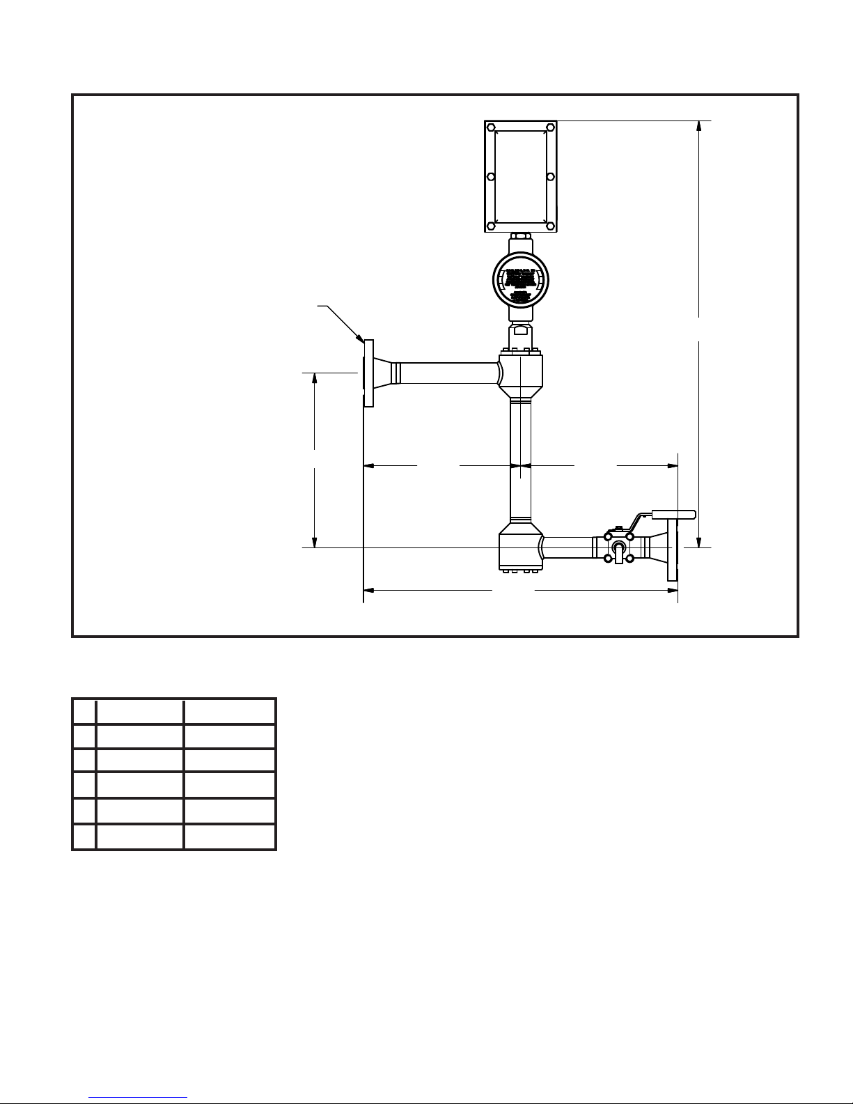
TheKAM®OWD®owthroughmodelcanbeusedinananalyzer/densitometerloop,forprocessoptimizationwhere
anaccuratedeterminationofwaterconcentrationisimportant,anditisvitaltooptimizingthe
desalinizationprocess.Placedonthedesaltersampleline,oroneachsampleline,theKAM®OWD®owthrough
modelprovidesreal-timeinformationaboutyourdesalterperformance.
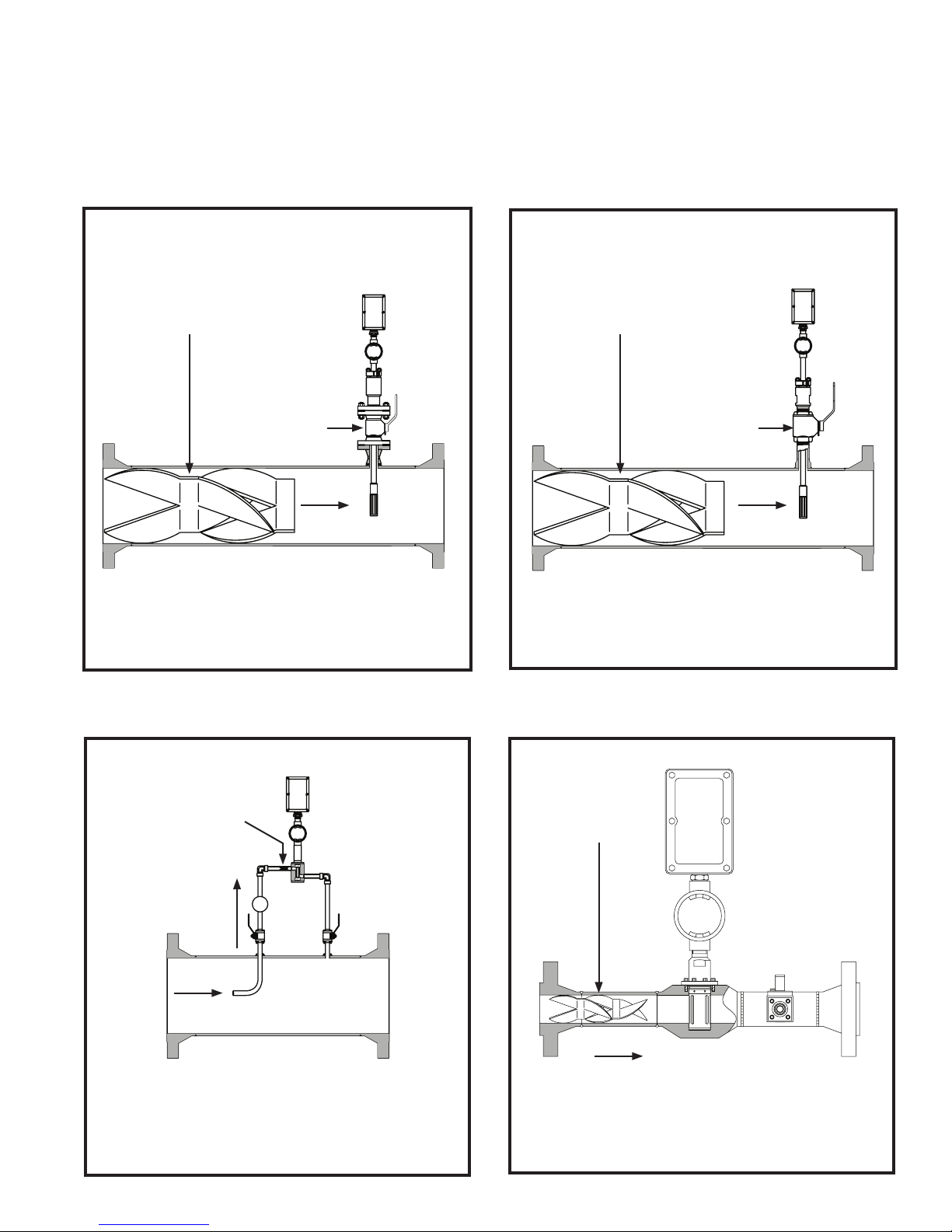
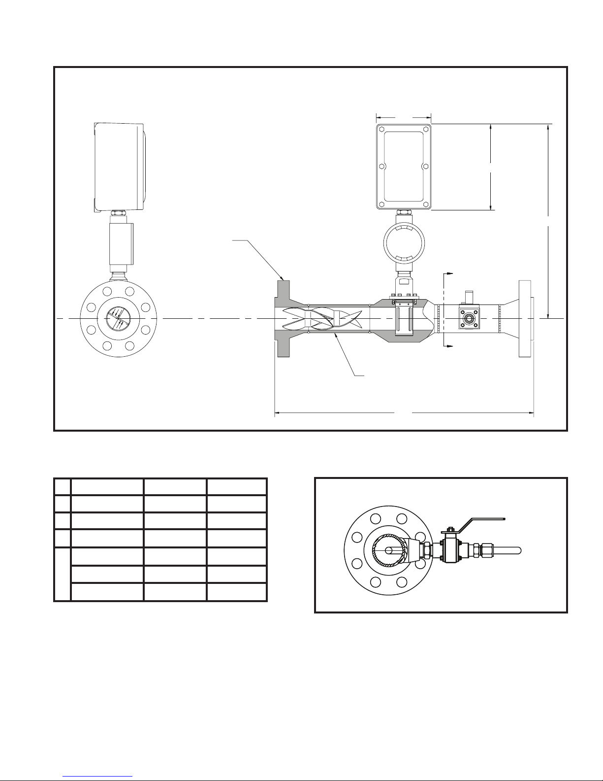
Toensurethehighestdegreeofaccuracy,theowmustbehomogenous.InstalledupstreamofyourOWD®
sensor,thepatentedKAM®SMP™StaticMixingPlateorKAM®SMS™StaticMixingSpoolcreateafully
homogenousmixtureinyourpipeline.Inlowvelocitysituations,theuseofaKAMMLMeasurementLoopmay
berequiredinordertocreateahomogenousowformeasurement.Propercalibration,alsokeytocomplete
accuracy,canbeachievedintheeldwiththeKAM®PKFPortableKarlFischerMoistureAnalyzer.
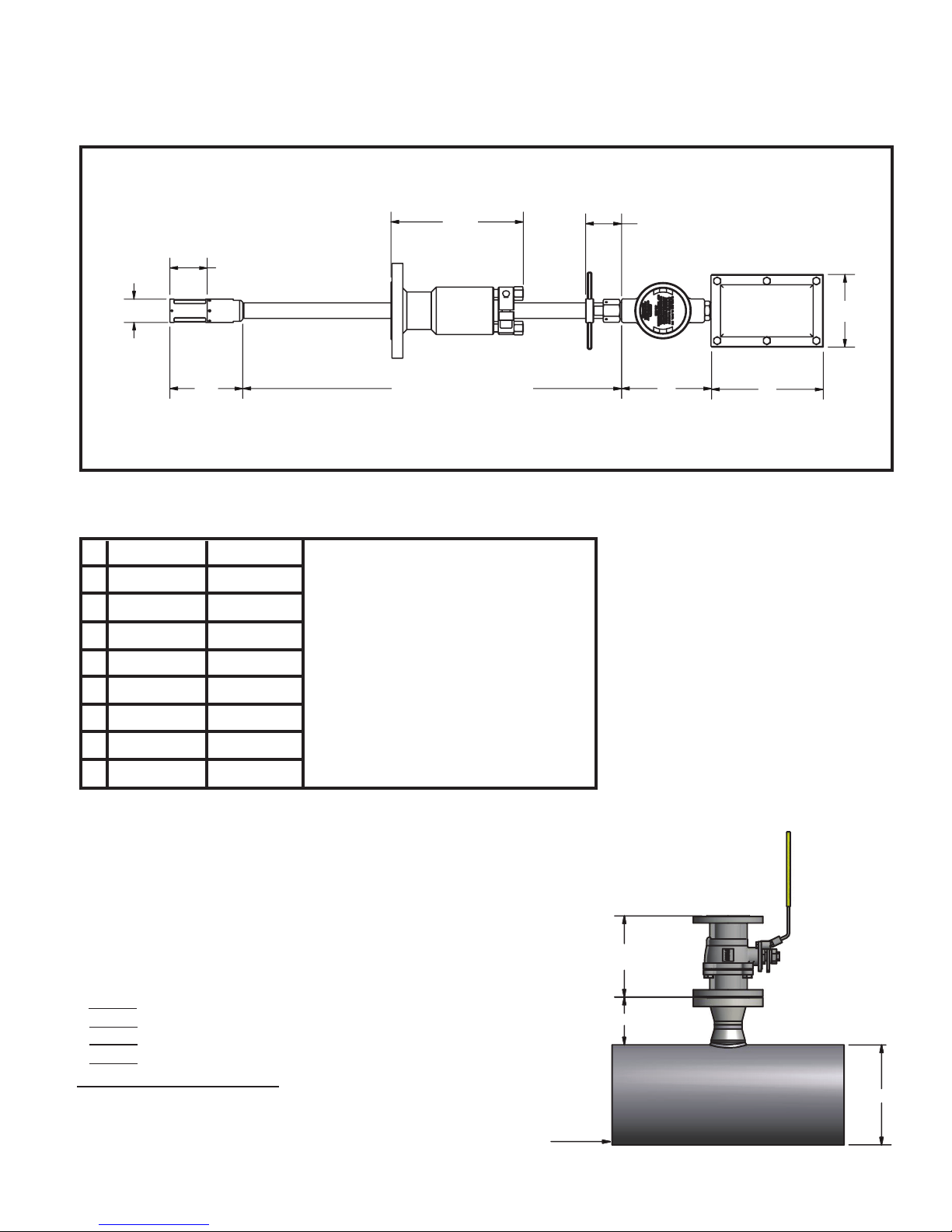
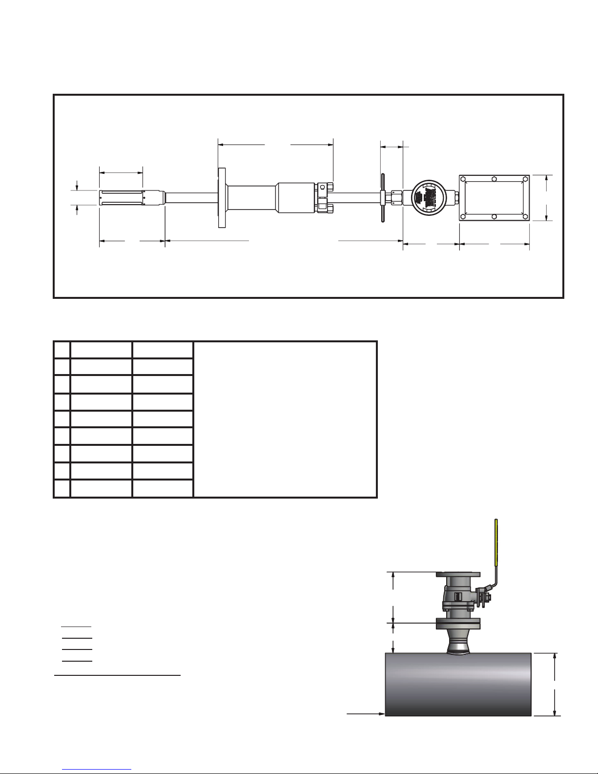
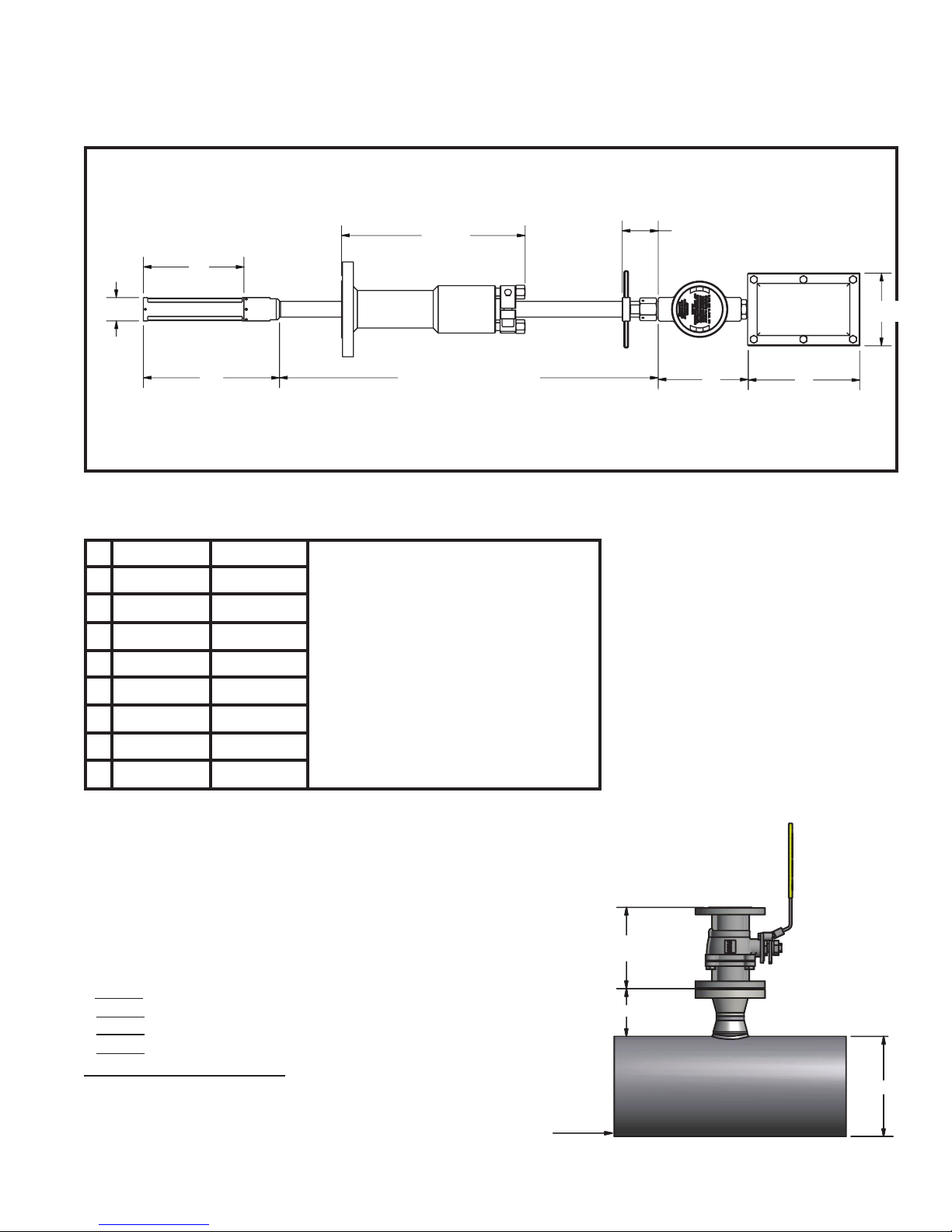
Becauseitcanbeinsertedintoyourpipeortankthrougha2",3",or4"hottap,theOWD®sensorhelpsyouavoid
costlydrainage,theneedforabypassloop,orhavingtocutasectioninthepipe.Allwettedpartsaremachinedfrom
316stainlesssteel.Shaftlengthsfrom1to3feetareavailablewithoff-the-shelflengthscomingin12",24",and36".
Metricandcustomlengthsareavailable.
Range(waterinoil) 0-1% 0–5% 0–10% 0–20% 0–40% 0–100%
Accuracy(atlistedrange)0.01% 0.05% 0.10% 0.20% 0.40% 1.00%
TABLE 1-5 MEASUREMENTCAPABILITIES:CALIBRATEDRANGEANDACCURACIES
NOTE:TheKAMOWDcanbecalibratedtoanyrangebetween0-1%and0-100%.
THEORY OF OPERATION

OWDMANUAL 1114 KAM CONTROLS, INC.
4
SPECIFICATIONS
Media: Crudeoil,renedproductsandchemicals
Material: Wettedparts-316stainlesssteel/titanium(Othermaterialsavailable)
Fluidtemp: To300ºF(149ºC)Hightempmodelavailableto600ºF(315ºC)
Electronicstemp: -40ºFto158ºF(-40ºc to +70ºC)Tempsbelow0ºrequireheattracing
Powerrequirements: 24VDC/1ampat24watts
Accuracy: 1%offullrange**
Repeatability: +/-0.01%
Resolution: +/-0.01%
Minimum water detection: 100 PPM
Outputs: 4–20mA
4-20mAor0–5VDC
Alarm relay
RS232/RS485
HART
Mounting: ½",¾",1"or2"FNPTowthrough
(Othersizes,includingmetric,areavailable)
2"MNPTsealhousing
2",3",or4"angedsealhousing
Pressureratings: ANSI150,300,600,900,1500
Flowconditions: WellmixedinaccordancewithAPIMPMSChapter8,Section2,Table1
Sensordimensions: Ø1.5"x4.5"to14.5"(38mmhx114mmto368mm)dependingonrange
EXenclosures: Sensorelectronics-3"x6"x3"
(76mmx152mmx76mm)
Shaftlength: 12"to36"
(305mmto914.4mm)
Off-the-shelflengthsare12",24",and36"
(609.6mm,762mm,914.4mm,)
PipeSize: ½"to48"(15mmto1200mm)
Weight: from20lbs.(9kg)
*TheKAM®OWD® mustbeinstalledinaccordancewithAPIMPMSChapter8,Section2,Table1.
**Ifentrainedgasisconstant,itseffectisfactoredout.IfentrainedgasisintroducedorremovedafterOWD®
calibrationitwillshiftwatercutmeasurementbyapproximately1-2%forevery1%changeingaslevels.

OWDMANUAL 1114 KAM CONTROLS, INC.
5
SPECIFICATIONS CONTINUED
DIMENSIONAL DRAWINGS 0-100% MODELS
CALCULATING SHAFT LENGTH 0-100% MODELS
D1
Valve
Length
Main Pipe
Pipe OD
Determineminimumshaftlengthforproperinsertioninthepipeline.
Off-the-shelflengthsare12",24",and36".
TABLE 2-2 DIMENSIONS INSERTABLE OWD® SENSOR 0-100%
C
DE
CustomShaft
Lengths
AB
FG
H
FIG. 2-1 INSERTABLE OWD® SENSOR 0–100%
A
B
C
D
E
F
G
H
INCHES
1.48
2.4
4.62
max11.65
2.3
5.7
7
4.6
MM
38
61
117
296
58
145
178
117
ShaftLengthsareavailablein.5"
(12.7mm)increments.
Standardsizesare24",30",36",48",
and60"(609.6mm,762mm,914.4mm,
1219mm,1524mm).
*Sealhousingdimensionsvaryaccordingtoangesizeandpressurerating.11.65"isthemaximumlength
requiredincalculatingshaftlength.
D1
+ ValveLength:
+ PipeODx.5:
+ Sealhousinglength
– Probefactor
= Total/minimumshaftlengthforproper
insertion distance
13"
1"

OWDMANUAL 1114 KAM CONTROLS, INC.
6
SPECIFICATIONS CONTINUED
TABLE 2-4 DIMENSIONS INSERTABLE OWD® SENSOR 0-20%
C
DE
Electronics
Enclosure
CustomShaft
Lengths
AB
FG
H
FIG. 2-3 INSERTABLE OWD® SENSOR 0–20%
A
B
C
D
E
F
G
H
INCHES
1.48
4.4
6.62
max 13
2.3
5.7
7
4.6
MM
38
112
168
330
58
145
178
117
ShaftLengthsareavailablein.5"
(12.7mm)increments.
Standardsizesare24",30",36",48",
and60"(609.6mm,762mm,914.4mm,
1219mm,1524mm).
DIMENSIONAL DRAWINGS 0-20% MODELS
CALCULATING SHAFT LENGTH 0-20% MODELS
*Sealhousingdimensionsvaryaccordingtoangesizeandpressurerating.13"isthemaximumlength
requiredincalculatingshaftlength.
D1
Valve
Length
Main Pipe
Pipe OD
Determineminimumshaftlengthforproperinsertioninthepipeline.
Off-the-shelflengthsare12",24",and36".
D1
+ ValveLength:
+ PipeODx.5:
+ Sealhousinglength
– Probefactor
= Total/minimumshaftlengthforproper
insertion distance
13"
2"

OWDMANUAL 1114 KAM CONTROLS, INC.
7
SPECIFICATIONS CONTINUED
D1
+ ValveLength:
+ PipeODx.5:
+ Sealhousinglength
– Probefactor
= Total/minimumshaftlengthforproper
insertion distance
C
DE
Electronics
Enclosure
CustomShaft
Lengths
AB
FG
H
TABLE 2-6 DIMENSIONS INSERTABLE OWD® SENSOR 0-5%
FIG. 2-5 INSERTABLE OWD® SENSOR 0–5%
A
B
C
D
E
F
G
H
INCHES
1.48
6.4
8.62
max 13
2.3
5.7
7
4.6
MM
38
163
219
330
58
145
178
117
ShaftLengthsareavailablein.5"
(12.7mm)increments.
Standardsizesare24",30",36",48",
and60"(609.6mm,762mm,914.4mm,
1219mm,1524mm).
DIMENSIONAL DRAWINGS 0-5% MODELS
CALCULATING SHAFT LENGTH 0-5% MODELS
D1
Valve
Length
Main Pipe
Pipe OD
13"
3"
Determineminimumshaftlengthforproperinsertioninthepipeline.
Off-the-shelflengthsare12",24",and36".
*Sealhousingdimensionsvaryaccordingtoangesizeandpressurerating.13"isthemaximumlength
requiredincalculatingshaftlength.

OWDMANUAL 1114 KAM CONTROLS, INC.
8
SPECIFICATIONS CONTINUED
FIG 2-7 2" OWD®FLOWTHROUGH SENSOR WITH INTEGRATED KAM® SMS™ STATIC MIXING SPOOL
TABLE 2-8 DIMENSIONS
A
B
C
D
FLANGESIZE
N/A
N/A
N/A
2"150#
2"300#
2"600#
MM
119
184
419 ± 13
533
559
559
INCHES
4.7
7.25
16.5±0.5
21
22
22
A
E
E
B
C
D
2"150#,300#,or600#weld-
neckanges
SS316bothends
2"sch.seamlesspipeSS316
FIG 2-9
SS316½"samplevalvewith
½"pitotprobe

OWDMANUAL 1114 KAM CONTROLS, INC.
9
SPECIFICATIONS CONTINUED
TABLE 2-11 DIMENSIONS
A
B
C
D
E
MM
282
Min.152
Min254
406
691
INCHES
11. 1
Min.6"
Min.10"
Min.16"
27.2
A
E
BC
D
FIG 2-10 1" OWD®0-1% FLOWTHROUGH
1"WNRFFlanges

OWDMANUAL 1114 KAM CONTROLS, INC.
10
KAM SMS
STATIC MIXING
SPOOL
INSTALLATION
PLEASENOTE:InallKAMOWDInstallations,theusershouldinsurethattheKAMOWDisinstalledinaturbulent
owwiththeReynoldsNumberabove2000.Additionally,allKAMOWD'sshouldbeinstalledinaccordancewithAPI
MPMSChapter8,Section2,Table1.
ForKAMOWD'soperatinginoil-continuousow,thesensormustbeinstalledintheverticaldownowwithamini-
mumowvelocityof4feetpersecond.AKAMSMSStaticMixingSpoolisrequirediftheowvelocityisbetween4
and7feetpersecond.FIG.3-1.Lowrangemodelsalsorequireacorrecteddensityinput.
ForKAMOWD'soperatingintheOilContinuousPhase,thesensormustbeinstalledintheverticaldownow.A
KAMSMSStaticMixingSpoolisrequirediftheowvelocityisbetween4and7feetpersecond.FIG.3-1.
ForKAMOWD'soperatingintheWaterContinuousPhase,thesensormustbeinstalledintheverticalupow.A
KAMSMSStaticMixingSpoolisrequirediftheowvelocityisbetween4and7feetpersecond.FIG.3-2.
Insituationswheretheowvelocityislessthat4feetpersecond,KAMCONTROLSrecommendstheinstallation
ofaKAMMLMeasurementLoop,incorporatingsuctionandinjectionnozzles,apump,andtheOWDonaseparate
loop,ensuringahomogenous,high-velocityowacrossthemeasurementsensor.FIG.3-3.
TheKAMOWDmaybeinstalledhorizontallywhentheminimumowvelocityisabove10feetpersecond.
KAM SMS
STATIC MIXING
SPOOL
Q
LOWRANGEAND
OIL CONTINUOUS
PHASE OPERATION
Q
WATER CONTINUOUS
PHASE OPERATION
FIG. 3-3 INSTALLED ON A
KAM ML MEASUREMENT LOOP
INSTALLATION FLOW REQUIREMENTS
Q
INJECTION
SUCTION
TheKAMMLMeasurementLooputilizesa
pumptodrawarepresentativeowfromthemain
lineintoacirculationloop,incorporatingaKAM
OWD.Theloopowisinjectedbackintothemain
pipelineupstreamofthesuctionsite,
creatingmixingandhomogeneitypriorto
suction.Ahomogenousowof10-13fpsis
maintainedatthesensorheadforthemost
accurate measurement at all times.
FIG. 3-1 INSTALLATION VERTICAL FLOW DOWN
FIG. 3-2 INSTALLATION VERTICAL FLOW UP

OWDMANUAL 1114 KAM CONTROLS, INC.
11
INSTALLATION CONTINUED
LACT UNIT INSTALLATION
TheKAMOWDshouldbeinstalled
onaTwiththeowperpendicularto
theshaft.AKAMSMPStaticMixing
Plateshouldbeinstalled3to5pipe-
linediametersbeforethesensor.For
allotherinstallations,pleaseconsult
withfactory.
CAUTION:NeverinstalltheOWDon
aTwiththetopofthesensorfacing
intotheow.Thiswillminimizeow
acrosstheantennasandresultin
inaccurate measurement.
0-5%modelsrequireacorrected
densityinputinordertoachieve
stated accuracy.
Flow
KAMSMPStaticMixingPlate
installed3to5pipeline
diameters prior to sensor
FIG. 3-4 LACT UNIT

OWDMANUAL 1114 KAM CONTROLS, INC.
12
INSTALLATION CONTINUED
GENERAL INSTALLATION DO'S AND
DON'TS
Always install OWD®
sensorswiththe
electronics enclosure
shadedfromdirect
sunlight.
DONOTuseTeon
tapeonthreadscon-
nectingtotheOWD®
owthroughsensor.
DOuseliquidthread
sealant.

OWDMANUAL 1114 KAM CONTROLS, INC.
13
INSTALLATION CONTINUED
Removealltheprotectivepackagingmaterials,andensurethattheOWD®sensorwasnotdamaged
duringtransit.
REMINDER:PleaserefertotheInstallationFlowRequirementsonP.9ofthismanualtoensurepropersensor
placementwhereatallpossible.FlowconditionsmustsatisfyAPIMPMSChapter8.2requirementsinorderto
achieveaccurateOWDperformance.
Incoldweather,ifOWDisexposedtoanopenenvironment,KAMCONTROLSrecommendsoperatorsinsulate
theOWD,andifthepipelineisheatedthattheheatingtracebeextendedtoincludetheOWD.
IfthepipelineisnotgoingtoowforextendedamountoftimeandthepipeisnotheatedthenOWDshouldbe
takenouttoavoiddamagetothesensorprobebyfreezingwater.
PRIORTO INSTALLATION
MAIN LINE INSTALLATION
INITIAL CALIBRATION
TheKAM®OWD®sensorshouldbeinstalled
accordingtoFIG.3-13.Afull-openingballvalveis
usedtoisolatetheOWD®sensorfromthepipeline
duringinstallationorremoval.Thesealhousingof
theOWD®sensorallowstheprobetobeinserted
andremovedfromthepipeunderpressureandow
conditions.Itistheuser’sresponsibilityto
ensurethattheOWD®sensorbeplacedatthemost
representativepointwithintheow
prole(seelocationrecommendationsabove).
TheOWD®sensorshouldbeinsertedsothatthe
windowoftheprobeislocatedinthecenterofthe
diameterofthepipeline.
Note:Iflinepressureexceeds100psi,useaKAM®
ITInsertionToolwheninstalling/removing
theKAM®OWD®sensor.
LockingCollar
SealHousing
Full-opening
Ball Valve
SocketCapScrew
FIG. 3-5 KAM®OWD®INSTALLED ON A MAIN PIPE
ThoughtheOWDhasbeencalibratedinthefactory,operatorsshouldconductaninitialcalibrationinprocess
conditions.Thiscanbedoneintwoways:
Off-line:Priortoinstallation,operatorscangothroughtheproceduresforoff-linecalibrationoutlinedonpage25ofthis
manual.Thismethodrequiressamplesof100%producedwateranddryoiloroilwithaknownpercentageofwater.
On-line:Afterinstallation,operatorscanfollowcalibrationproceduresforin-linecalibrationoutlinedonpage25ofthis
manual.Thismethodrequiresaccuratesamplingandsampleprocessing.

OWDMANUAL 1114 KAM CONTROLS, INC.
14
Priortomountingverifythatthetipofthesensor
isallthewayinsidethesealhousing.
FIGS.3-14,3-15.
Ifsensorisnotfullyenclosedinsidetheseal
housing,pulltheshaftbackuntiltheprobeis
allthewayinthesealhousingandtighten
theSocketCapScrewsonthelockingcollar.
ThiswillpreventtheOWD®shaftfromsliding
andtheprobefromgettingdamagedduring
mounting.
1.
2.
FIG. 3-6
FIG. 3-7
INSTALLATION CONTINUED
Measurethedistance(D1)fromtheoutsidediameterofmainpipetotheendofthe
connectionwheretheOWD®sensorisgoingtobeinstalled.FIG.3-16.
D1
D1
CalculatetheminimuminsertiondistancefortheOWD®.
Minimuminsertiondistance(MID)=
D1 +
PipeWallThickness(WT)+
GasketThickness+
A(SeeTABLE3-16)
ExampleforD1=16",WT=1/4",
GasketThickness=1/8"anda0-100%OWD®sensor:
MID=16+1/4+1/8+3
MID=193/8"
4.
3.
FIG. 3-8
A/INCHES
7"
5"
3"
OWD®RANGE
0-5%SENSOR
0-20%SENSOR
0-100%SENSOR
TABLE 3-9

OWDMANUAL 1114 KAM CONTROLS, INC.
15
INSTALLATION CONTINUED
MeasurethecalculatedMIDfromthetopofthe
LockingCollarandplaceamarkwithapermanent
markerortapeontheShaft.FIG.3-18.
5.
MID
6. BoltorscrewtheOWD®sensortothevalveordesignatedinstallationlocation.
(KAMCONTROLSrecommendsusingthreadsealantandnotTeontapeforthethreadedOWD®).
Openfullopeningvalve.7.
LoosenSocketCapScrewsonthelockingcollar.
8.
FIG. 3-10
PushOWD®sensorinuntilthemarkisatthetopedgeofthelockingcollar.EnsurethatOWD®owindicatoris
alignedwithpipelineowdirection.FIG.3-19.
9.
Mark
Re-tightentheSocketCapScrews.
TightenthehexnutsholdingdowntheLockingCollaronehalfturn.(Fig.3-19)Theseshouldneverbeover-tight-
ened.Theirmajorfunctionistoapplylightpressureonthechevronpackingtoensureasealbetweentheseal
housingbodyandtheinsertionshaft.
10.
11.
REMOVINGTHE OWD®SENSOR
ToremovetheOWD®sensor,rstshutoffpowertotheinstrument.LoosentheSocketCapScrewontheLockDown
Collar.SlidetheOWD®sensorupwarduntiltheproberestsinsidethesealhousing.Next,closetheFull-openingBall
Valvetightly.Drainoilfromvalveifpossible.TheOWD®sensormaynowbeunboltedfromthesystem.
Note:Iflinepressureexceeds100psi,useaKAM® ITInsertionToolwheninstalling/removing
theKAM®OWD®sensor.
RemovalshouldbeconductedinaccordancewithallregionalandClassrequirements.
FIG. 3-11
Hex Nuts

OWDMANUAL 1114 KAM CONTROLS, INC.
16
INSTALLATION CONTINUED
REMOVINGTHE OWD®SENSOR FROM FLOWTHROUGH SPOOLS WITH FIXED INSERTION
ToremovetheOWD®sensor,rstshutoffpowertothe
instrument.Discontinueowinloopfromthemainline
anddrainuidfromloop.Theprobecanremovedfromthe
housingbyremovingscrewsoncollar.Fig.3-23.Theprobe
canthenbeliftedfromthecellfortesting/inspection/cali-
bration purposes.
Removalshouldbeconductedinaccordancewithallre-
gionalandClassrequirements.
FIG. 3-12
Hex screws

OWDMANUAL 1114 KAM CONTROLS, INC.
17
INSTALLATION CONTINUED
WIRING
Kam
Controls
Incorporated
3939 Ann Arbor Drive
Houston, TX 77063 USA
Tel + 1 713 784 0000
Fax + 1 713 784 0001
www.Kam.com
OWD Rev. 4
KAM OWD
Made in USA
24V (+) in
4-20mA (-)
24V (-) in
4-20mA (+)
ANA OUT (-)
ANA OUT (+)
DIG OUT (-)
DIG OUT (+)
AIN2
RS485 (+)
RS485 (-)
GND
RS232 RX
GND
RS232 TX
DIG IN (-)
DIG IN (+)
GND
FIG. 3-13 WIRING DIAGRAM 0-100% MODELS
D1
R1
+

OWDMANUAL 1114 KAM CONTROLS, INC.
18
INSTALLATION CONTINUED
INPUTS
24V(–)IN GND
24V(+)IN 24-30VDC
DIGIN(–) Pulseinput,discreteinputfordifferentmodesofoperation(0or5volt)
DIGIN(+)
AIN2 DensityIn–Notrequiredon0-100%models
OUTPUTS
4-20mA(–) Currentoutput,sourcepowered.Settorequisitepercentwateratfactory.
4-20mA(+)
ANOUT(–) Canbe4-20mAoranalogvoltage(usedforlocaldisplayortopassdensitytoPLC)
ANOUT(+)
DIGOUT(–) Alarmorrelay(digitalcontactclosure)
DIGOUT(+)
INPUT/OUTPUT
RS232 Consoleport–communicationinterfaceforcalibration,connectiontoPLC
RS485 Modbusinterface
LED INDICATORS
D1 Power
SERIAL PORT CONNECTIONS
DB9(female)
5 GND
3 RS232RX
2 RS232TX
AllwiringandmaintenanceontheKAMOWDmustbedoneinaccordancewithregionalandclassicationre-
quirements.Itistheuser'sresponsibilitytounderstandtheserequirements.
ItisalsorecommendedthattheOWDbewiredwithexiblewiring/conduitwithadditionalslack/lengthinthe
wiretoaccommodateinsertion,removal,andtesting.
Operator'sshouldtakeallpossibleprecautionstoavoidanymoisturefromenteringtheelectronicsenclosure.
Theenclosureshouldnotbeleftopenininclementweatherorforlongperiodsoftime,especiallyduringopera-
tionascondensationwillaccumulate.Lidshouldbetightlyscrewedshut,allconduitsshouldbesealedand
securedinaccordancewithregionalandclassicationrequirements,andunused3/4"NPTopeningsshouldbe
sealwithprovidedplug.Donotpowerwashtheunit.

OWDMANUAL 1114 KAM CONTROLS, INC.
19
FIG. 3-14 WIRING DIAGRAM OWD MODELS WITH RANGES OTHERTHAN 0-100%
INSTALLATION CONTINUED
3939 Ann Arbor Drive
Houston, TX 77063 USA
Tel + 1 713 784 0000
Fax + 1 713 784 0001
E-mail [email protected]
www.Kam.com
Made in USA
V (+) in
AGND
V (-) in
AOUT0
AGND
AOUT1
DENSITY
DOUT
GND
GND
RS485 (+)
RS485 (-)
GND
DIN
GND
GND
RXDO
TXDO
TEC+
D2
24-30VDCPower
4-20mAOutput
4-20mAOutputor
analogvoltage
Alarm or Relay
Density Input
FactoryUse
RS485
RS232
FactoryUse
Main power
indicator
Sharedground
(RS485andRS232)
Table of contents
Other KAM Measuring Instrument manuals

KAM
KAM LRW User manual

KAM
KAM BLUE MOVER 500 SD FSCAN User manual

KAM
KAM Ultimate V2 User manual

KAM
KAM TRI 160 User manual

KAM
KAM Simple Precision PKF User manual

KAM
KAM Star Cluster Micro V2 User manual

KAM
KAM DMX Laser40 FScan User manual

KAM
KAM Simple Precision CHA User manual

KAM
KAM Tri140 FScan User manual

KAM
KAM Combi Cluster User manual
Popular Measuring Instrument manuals by other brands

TSI Instruments
TSI Instruments Aerotrak 9303 manual

DROPSA
DROPSA FLOW MASTER II User and maintenance manual

H.E. Anderson
H.E. Anderson Ratio:Guard Advanced manual

MRC
MRC NIR-CS-3000BT user guide

Nigos
Nigos RVD-904 user manual

PCB Piezotronics
PCB Piezotronics IMI SENSORS 605B11 Installation and operating manual