4 Kmstrup A/S • 5512853_C1_GB_01.2017
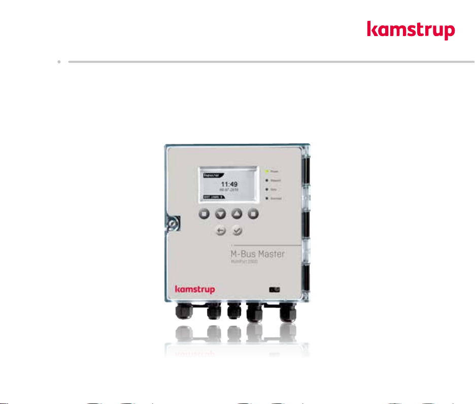
M-Bus Mster MultiPort 250D
1 Introduction
M-Bus is bus system, which is specilly suited for reding wter, het, cooling, gs nd electricity consumption
meters.
An M-Bus system consists of n M-Bus Mster nd number of meters with M-Bus interfce. A network cn include
different meter types nd brnds. The cble type used is typiclly twisted pir copper.
The connected meters re red either directly by the mster with dt ppering on the mster’s disply or by reding
progrm which is connected to one of the mster’s communiction ports.
The mster powers the M-Bus slve modules in the meters. Bttery supplied meters thereby chieve longer bttery
lifetime.
The mximum size of n M-Bus network using Kmstrup M-Bus Mster MultiPort 250D is 250 meters. If number of
msters re configured s repeters nd coupled in cscde nd only secondry ddressing is used, totl of 1,250
meters cn be connected, nd the totl cble length cn be up to pprox. 14 km.
If primry ddressing is used, up to 250 meters cn be connected.
Communiction in the M-Bus network is synchronous seril bit trnsmission in hlf duplex, which mens tht it is only
possible to communicte in one direction t time.
Communiction speed cn be 300, 2400 or 9600 bud.
It is not necessry to connect PC to the mster during instlltion, mintennce nd troubleshooting in the M-Bus
network s the mster itself includes the functions needed. Opertion is crried out vi disply nd front keys.
M-Bus is stndrdized ccording to EN 13757-2 nd EN 13757-3.
1.1 Design
M-Bus Mster MultiPort 250D is built into solid cbinet, which complies with protection clss IP 67.
The front consists of bcklit LCD, 6 keys, 4 sttus LEDs nd n opticl eye.
The power supply is switch mode type which enbles you to connect the mster to power supply between 100 nd
240 volts. The frequency must be 50-60 Hz.