Kamstrup MULTICAL 403 User manual

Instlltion nd user’s guide
MULTICAL® 403
Kamstrup A/S · Indusrivej 28, Silling · DK-8660 Sknderborg · T: +45 89 93 10 00 · info@kmsrup.com · kmsrup.com

2 Kmsrup A/S • 55121739_B1_GB_02.2020
MULTICAL® 403
Information
Permissible operating conditions / measuring ranges
Approved he meer in ccordnce wih MID nd EN1434:
Temperure Rnge q: 2 °C…180 °C DΘ: 3 K…178 K
Flow sensor (emperure of medium) qq: 2 °C…130 °C
Approved cooling meer in ccordnce wih DK-BEK 1178 nd EN1434:
Temperure Rnge q: 2 °C…180 °C DΘ: 3 K…178 K
Flow sensor (emperure of medium) qq: 2 °C…130 °C/qq: 2 °C…50 °C (MULTICAL® 403-C)
MID designation
Mechanical environment
Clss M1 nd M2
Electromagnetic environment
Clss E1 (housing/ligh indusry). The meer’s conrol cbles mus be drwn min. 25 cm
disnce from oher insllions.
Climatic environment
Non-condensing, closed locion (insllion indoors), mbien emperure 5…55 °C.
Maintenance and repair
The disric heing supplier cn replce emperure sensor pir, bery nd communicion
module. The flow sensor mus no be sepred from he clculor. Oher repirs require
subsequen reverificion in n ccredied lborory.
Selecting a temperature sensor pair
MULTICAL® 403-W - P500 - He meer
MULTICAL® 403-T - P500 - He/cooling meer
MULTICAL® 403-V - P100 - He meer
MULTICAL® 403-C - P500 - Cooling meer
Battery for replacement
Kmsrup ype HC-993-02 (1 x D cell)
Kmsrup ype HC993-09 (2 x A cell)
Communication Modules
For n overview of vilble modules we refer o secion 9, pge 16.

3Kmsrup A/S • 55121739_B1_GB_02.2020
MULTICAL® 403
Contents
1 General information 4
2 Mounting of temperature sensors 5
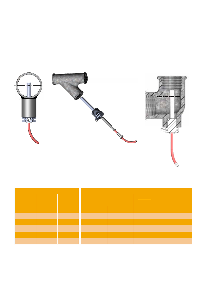
2.1 Shor direc sensor (DS) 5
2.2 Pocke sensor (PL) 6
2.3 Temperure sensor compibiliy wih flow sensors 6
3 Mounting of flow sensor 7
3.1 Mouning of couplings nd shor direc sensor in flow sensor 7
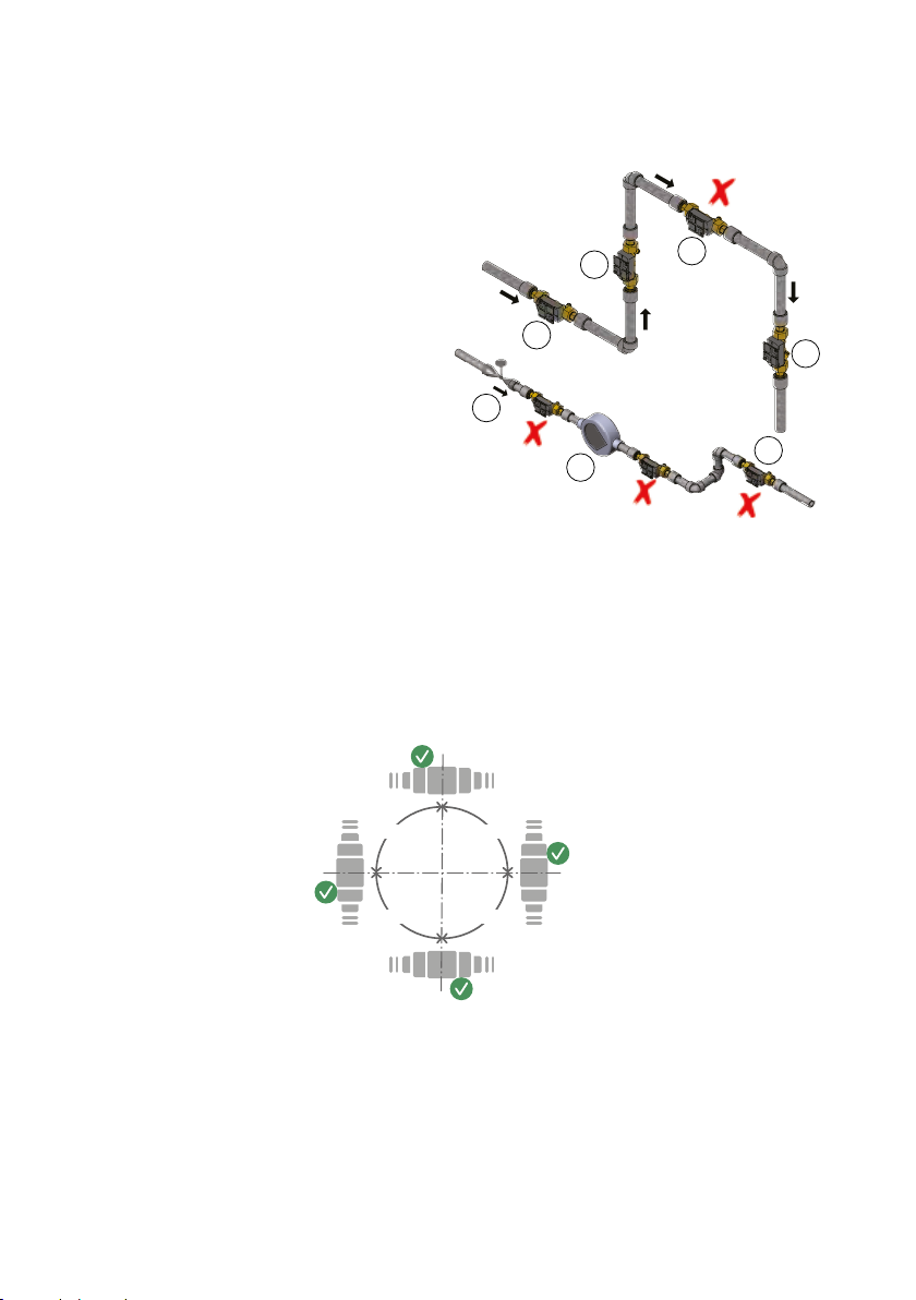
3.2 Flow sensor posiion 8
3.3 Insllion of MULTICAL® 403 flow sensor 8
3.4 Insllion exmples 10
3.5 Humidiy nd condension 10
4 Mounting the calculator 11
4.1 Compc mouning 11
4.2 Wll mouning 11
4.3 Posiion of clculor 12
5 Information codes ”INFO” 13
6 Power supply 14
6.1 Bery supply 14
6.2 Mins supply 14
7 Testing of function 15
8 Electrical connection 15
9 Communication modules 16
9.1 Module overview 16
9.2 Pulse inpus 16
9.3 Pulse oupus 17
9.4 D Pulse, inpus (In-A, In-B), ype HC-003-10 17
9.5 D Pulse, oupus (Ou-C, Ou-D) , ype HC-003-11 17
9.6 Wired M-Bus, inpus (In-A, In-B), ype HC-003-20 18
9.7 Wired M-Bus, oupus (Ou-C, Ou-D), ype HC-003-21 18
9.8 Wireless M-Bus, inpus (In-A, In-B), 868 MHz, ype HC-003-30 18
9.9 Wireless M-Bus, oupus (Ou-C, Ou-D), 868 MHz, ype HC-003-31 18
9.10 Anlog oupus 2 x 0/4…20 mA, ype HC-003-40 19
9.11 PQT Conroller, ype HC-003-43 19
9.12 Low Power Rdio, inpus (In-A, In-B), 434 MHz, ype HC-003-50 19
9.13 Low Power Rdio GDPR, inpus (In-A, In-B), 434 MHz, ype HC-003-51 19
9.14 LON TP/FT-10, inpus (In-A, In-B), ype HC-003-66 20
9.15 Modbus RTU, inpus (In-A, In-B), ype HC-003-67 20
10 Set-up via front keys 21

4 Kmsrup A/S • 55121739_B1_GB_02.2020
MULTICAL® 403
1 General information
'Please read this guide carefully before mounting the energy meter.
In case of incorrect mounting, Kamstrup's guarantee obligations no longer apply.
Plese noe h he following insllion condiions mus be obeyed:
- Pressure sge: PN16/PN25, see mrking.
- Pressure sge, Kmsrup
sensor pir ype DS: PN25
- Pressure sge, Kmsrup
pocke sensors ype PL: PN25
A medium emperures bove 90 °C we recommend flnge sensors s well s wll-mouning of
clculor.
A medium emperures below mbien emperure, MULTICAL® 403 mus be wll mouned nd
he condension-proof version, ype 403-C, mus be used. In cse of bidirecionl he/cooling
energy meering, ype 403-T is used.

5Kmsrup A/S • 55121739_B1_GB_02.2020
MULTICAL® 403
2 Mounting of temperature sensors
The emperure sensors used for mesuring inle nd oule emperures respecively,
consiue mched sensor pir, which mus never be sepred. According o EN 1434/OIML
R75, he cble lengh mus no be chnged. Should replcemen be necessry, boh sensors mus
be replced.
The sensor mrked wih red sign is o be inslled in he inle pipe. The oher sensor, mrked wih
blue sign, is o be inslled in he oule pipe. For mouning in he clculor, see he prgrph
”Elecricl connecion”.
Note: The sensor cbles mus neiher be exposed o jerking nor pulling. Plese be wre of his
when binding he cbles, nd be creful no o pull he binders unnecessrily igh s his
my dmge he cbles. Plese lso noe h emperure sensors mus be mouned from
below in cooling nd he/cooling insllions.
2.1 Short direct sensor (DS)
The shor, direc sensors up o DN25 cn be mouned in specil bll vlves wih buil-in M 10
socke for he shor direc sensor. They cn lso be mouned in insllions wih sndrd
ee-pieces. Kmsrup A/S cn supply R½ nd R¾ brss nipples h fi he shor direc sensors.
The shor direc sensor cn lso be mouned direcly in seleced flow sensors from Kmsrup A/S.
Fsen he sensors’ brss unions lighly (pprox. 4 Nm) using 12 mm fce wrench, nd sel he
sensors wih sel nd locking wire.

6 Kmsrup A/S • 55121739_B1_GB_02.2020
MULTICAL® 403
2.2 Pocket sensor (PL)
The sensor pockes cn be mouned in e.g. welding sleeve or in 45° lerl Y-piece. The ip
of he sensor pocke mus be plced in he middle of he flow. Push he emperure sensors s
deep s possible ino he pockes. If shor response ime is required, “non-hrdening” hermlly
conducive pse cn be used. Push he plsic sleeve on he sensor cble ino he sensor pocke
nd secure he cble by mens of he enclosed M4 seling screw. Fsen he screw wih your
fingers only. Sel he pockes using sel nd locking wire.
A
A
B
B
SECTION
A-A
SCALE
1 : 1
SECTION
B-B
SCALE
1 : 1
B
B
SECTION
B-B
SCALE
1 : 1
2.3 Temperature sensor compatibility with flow sensors
The size of he flow sensor deermines which emperure sensors you cn use nd how hey re
mouned. The below ble shows which emperure sensor ypes o use wih which flow sensor.
Flow sensor Temperature sensor
Cn be mouned in flow
sensor.
Cnno be mouned in flow
sensor.
qpDN G DS 27.5 DS 38 Ø5.8 mm pocket
0.6-1.5 15 G¾B X
0.6-1.5 20 G1B X
3.5-6 25 G5/4B X
10 40 G2B X
15 50 - X

7Kmsrup A/S • 55121739_B1_GB_02.2020
MULTICAL® 403
3 Mounting of flow sensor
Prior o insllion of he flow sensor, he sysem should be flushed nd proecion plugs/plsic
diphrgms removed from he flow sensor.
Correc posiion of he flow sensor ppers eiher from he clculor’s ype lbel or from he
disply where (indices he posiion in inle, wheres )indices he posiion in oule. The
flow direcion is symbolised by n rrow on he flow sensor.
3.1 Mounting of couplings and short direct sensor in flow sensor
The flow sensor cn be used in connecion wih
eiher PN16 or PN25 (see mrking).
Any provided blind plug, exension nd glnd
cn be used wih boh PN16 nd PN25.
In connection with flow sensors with the
nominal dimensions G¾Bx110 mm and
G1Bx110 mm, it must be checked if the thread
run-out is sufficient.
Couplings nd gskes re mouned s shown
in he figure. Mke sure o posiion he gske
correcly in he recess of he glnd s shown in
he deils excerp in he figure.
Gske
Momen ~4 Nm
Gske
Kmsrup flow sensors require neiher srigh inle nor srigh oule o mee he Mesuring
Insrumens Direcive (MID) 2014/32/EU, OIML R75:2002 nd EN 1434:2015. A srigh inle secion
will only be necessry in cse of hevy flow disurbnces before he meer. I is recommended o
follow he guidelines of CEN CR 13582.

8 Kmsrup A/S • 55121739_B1_GB_02.2020
MULTICAL® 403
3.2 Flow sensor position
A Recommended posiion.
B Recommended posiion.
C Unccepble posiion due o risk of ir
build-up.
D Accepble posiion in closed sysems.
E Ough no o be plced immediely fer
vlve, wih he excepion of block vlves
(bll vlve ype) which mus be fully open
when no used for blocking.
F Ough no o be plced immediely before
or fer pump.
G Ough no o be plced immediely fer
double bend in wo plnes.
A
BC
D
E
FG
In order o void cviion, he bck pressure he flow sensor (he pressure he flow sensor
oule) mus be minimum 1.5 br qp(nominl flow) nd minimum 2.5 br qs(mximum flow).
This pplies o emperures up o pprox. 80 °C. The flow sensor mus no be exposed o pressure
lower hn he mbien pressure (vcuum).
3.3 Installation of MULTICAL® 403 flow sensor
90°
90°
90°
90°
The flow sensor cn be mouned horizonlly, vericlly or n ngle.

9Kmsrup A/S • 55121739_B1_GB_02.2020
MULTICAL® 403
3.3.1 Screw-type meters 0.6...2.5 m3/h
0°0°
-45°-45°
1
The flow sensor cn be mouned n ngle of 0° nd my be urned 90° downwrds.
3.3.2 Flange meters and screw-type meters ≥ 3.5 m3/h
1
22
-45°
0°
45°
0°
-45°
45°
The flow sensor cn be mouned n ngle of 0° nd my
be urned 45° upwrds or 90° downwrds.
Note: In insllions where he medi emperure is below he mbien emperure,
MULTICAL® 403-T or 403-C mus be used. A he sme ime, he flow sensor mus no be
inslled wih he plsic housing urned below 0°.

10 Kmsrup A/S • 55121739_B1_GB_02.2020
MULTICAL® 403
3.4 Installation examples
Threaded meter:
Flow from he lef Flow from he righ
Flange meter:
Flow from he lef Flow from he righ
3.5 Humidity and condensation
If here is risk of condension, e.g. in cooling sysems, condension-proof MULTICAL® 403,
ype 403-C, mus be used. In cse of bidirecionl he/cooling energy meering, ype 403-T is
used.

11Kmsrup A/S • 55121739_B1_GB_02.2020
MULTICAL® 403
4 Mounting the calculator
The MULTICAL® 403 clculor cn be mouned in differen wys; eiher direc on he flow sensor
(compc mouning), or on wll (wll mouning).
4.1 Compact mounting
Compc mouning mens h he clculor
is mouned direcly on he flow sensor. Hving
been mouned, he clculor is seled
wih sel nd locking wire. If here is risk of
condension (e.g. in cooling pplicions), he
clculor mus be wll mouned. Furhermore,
MULTICAL® 403 in cooling pplicions mus be
he condension-proof version, ype 403-C.
In cse of bidirecionl he/cooling energy
meering, ype 403-T is used.
The consrucion of MULTICAL® 403 lwys
provides minimum insllion deph in
connecion wih compc mouning. Due o he
design he mouning rdius in criicl plces
remins 60 mm, boh 45° nd 90° mouning
of he flow sensor.
R60
45°
90°
90°
R60
45°
90°
R60
45°
4.2 Wall mounting
MULTICAL® 403 cn be mouned direcly on n
even wll. Wll mouning requires wll fiing
(3026-655), which is vilble s n ccessory
o MULTICAL® 403. Use he fiing s emple
o mrk nd drill wo 6 mm holes in he wll
nd moun he fiing using he enclosed
screws nd rwlplugs. Moun MULTICAL® 403
on he wll fiing by sliding he clculor
ono he fiing in he sme wy s i is done in
connecion wih compc mouning.
Note: For qp3.5 flow sensors nd lrger i is
possible o demoun he brcke from
he flow sensor nd use i s wll
brcke.
45
45

12 Kmsrup A/S • 55121739_B1_GB_02.2020
MULTICAL® 403
4.3 Position of calculator
If he flow sensor is inslled in humid or
condensing environmen, he clculor mus
be wll mouned nd posiioned higher hn he
flow sensor.

13Kmsrup A/S • 55121739_B1_GB_02.2020
MULTICAL® 403
5 Information codes ”INFO”
MULTICAL® 403 consnly moniors number of imporn funcions. If serious error occurs in
he mesuring sysem or he insllion, flshing “INFO” will pper in he disply. The ”INFO”-
field keeps flshing s long s he error is presen no mer which reding you choose. The
”INFO”-field is uomiclly swiched off when he error hs been correced. The info code cn be
displyed in in TECH loop reding 2-017-00, for indicion of curren errors in MULTICAL® 403. The
info code consiss of 8 digis nd ech funcionliy hs is own digi dediced o he indicion
of relevn informion. For insnce ll informion concerning emperure sensor 1 is shown in
he disply s he second digi from he lef.
Display digit Description
1 2 3 4 5 6 7 8
Info t1 t2 0 V1 0 In-A In-B
1No volge supply
2 Low bery level
9 Exernl lrm (e.g. vi KMP)
1 1 Above mesuring rnge or swiched off
1 2 Above mesuring rnge or swiched off
2 1 Below mesuring rnge or shor-circuied
2 2 Below mesuring rnge or shor-circuied
9 9 Invlid emperure difference (1-2)
3V1 Air
4V1 wrong flow direcion
6 V1 > qsfor more hn n hour
8 Pulse inpu A, lekge in sysem
9 Pulse inpu A, exernl lrm
8 Pulse inpu B, lekge in sysem
9 Pulse inpu B, exernl lrm
Example:
1 0 2 0 0 0 9 0

14 Kmsrup A/S • 55121739_B1_GB_02.2020
MULTICAL® 403
6 Power supply
6.1 Battery supply
MULTICAL® 403 is vilble wih bery supply using eiher wo A-cell beries or one D-cell
bery. Opiml bery lifeime is obined by keeping he bery emperure below
30 °C, e.g. by wll mouning. The volge of lihium bery is lmos consn hroughou he
lifeime of he bery (pprox. 3.65 V). Therefore, i is no possible o deermine he remining
cpciy of he bery by mesuring he volge. ”INFO” code ”2xxxxxxx” however, indices low
bery level.
The bery cnno nd mus no be chrged nd mus no be shor-circuied. Used beries
mus be hnded in for pproved desrucion, e.g. Kmsrup A/S. Furher deils pper from
documen on hndling nd disposl of lihium beries (5510-408).
6.2 Mains supply
MULTICAL® 403 is vilble wih supply
modules for eiher 24 VAC or 230 VAC.
The modules re proecion clss II nd re
conneced vi wo-wire cble (wihou erh)
hrough he big cble bush, he second one
from he righ, he boom of he connecion
bse. Use connecing cble wih n ouer
dimeer of 5-10 mm nd ensure correc cble
sripping s well s correc mouning of cble
relief.
If connecing o 230 VAC, i is imporn o
mke sure h he whole insllion complies
wih curren regulions. The supply cble mus
no be proeced by fuse lrger hn he one
permied for he given cble size.
In connecion wih oher ypes of insllions
or requiremens for lrger fuses hn he
ones lised bove, i is necessry o consul
cerified elecricin for n individul evluion
of how he ype of insllion in quesion
should be crried ou.
Blck
Red
61
60 97
98
24 VAC supply
24 VAC
3.6 V
24 VAC
E.g. rnsformer 230/24 V, ype 66-99-403,
cn be used.
Note: MULTICAL® 403 cnno be powered
by 24 VDC.
Blck
Red
61
60
27
28
230 VAC supply
230 VAC
3.6 V
230 VAC
This module is used when he meer is supplied
direcly by he mins.
Note: Exernl supply mus only be conneced
o he supply module.

15Kmsrup A/S • 55121739_B1_GB_02.2020
MULTICAL® 403
7 Testing of function
Crry ou n operionl check when he energy meer hs been fully mouned. Open
hermoregulors nd vlves o enble wer flow hrough he heing sysem. Acive he fron
key of MULTICAL® o chnge disply reding, nd check h he displyed vlues for emperures
nd wer flow re credible vlues.
8 Electrical connection
The wo mched wo-wire sensors re
mouned in erminls 5 nd 6 (1) s well
s 7 nd 8 (2). The polriy of emperure
sensors 1 nd 2 is wihou impornce for he
funcionliy.
Plese lso see he posiion of he erminls in
he figure o he righ:
Terminal no. Standard heat and
cooling measurement
1 5-6 Sensor in inle pipe
(red lbel)
2 7-8 Sensor in oule pipe
(blue lbel)

16 Kmsrup A/S • 55121739_B1_GB_02.2020
MULTICAL® 403
9 Communication modules
MULTICAL® 403 cn be exended by wide rnge of exr funcions by mens of communicion
modules. Below, pulse inpus/oupus nd module ypes re briefly described.
Note: Before replcing or mouning modules, he supply o he meer mus be swiched off. The
sme pplies for mouning of n nenn.
9.1 Module overview
MULTICAL® 403 communicion modules:
Type No. Description
HC-003-10 D Pulse, inpus (In-A, In-B)
HC-003-11 D Pulse, oupus (Ou-C, Ou-D)
HC-003-20 Wired M-Bus, inpus (In-A, In-B)
HC-003-21 Wired M-Bus, oupus (Ou-C, Ou-D)
HC-003-22 Wired M-Bus, Therml Disconnec "#%
HC-003-30 Wireless M-Bus, inpus (In-A, In-B), 868 MHz
HC-003-31 Wireless M-Bus, oupus (Ou-C, Ou-D), 868 MHz
HC-003-40 Anlog oupus 2 x 0/4…20 mA "#
HC-003-43 PQT Conroller "#
HC-003-50 Low Power Rdio, inpus (In-A, In-B), 434 MHz %
HC-003-51 Low Power Rdio GDPR, inpus (In-A, In-B), 434 MHz %
HC-003-66 BACne MS/TP, inpus (In-A, In-B) "
HC-003-67 Modbus RTU, inpus (In-A, In-B) "
"The module requires h he meer is mins-supplied.
#The module requires n exernl power supply.
%The module requires specific configurion in he meer, see he module d shee for
deils.
9.2 Pulse inputs
Pulse inpus A nd B re used for connecion of
exr meers wih eiher Reed-swich oupu or
pssive elecronic pulse oupu.
Min. pulse durion is 30 ms. nd mx pulse
frequency is 3 Hz.
65 + Pulse inpu A
66 -
67 + Pulse inpu B
68 -
If module wih pulse inpus is mouned in MULTICAL®, he meer is uomiclly configured for
pulse inpus. Noe h he meer fcor (lires/pulse) mus mch he exr wer meers nd he
configurions of inpus A nd B. Afer delivery, he configurions of pulse inpus A nd B cn be
chnged by mens of he PC progrm METERTOOL HCW.

17Kmsrup A/S • 55121739_B1_GB_02.2020
MULTICAL® 403
9.3 Pulse outputs
Pulse oupus for energy nd volume re mde
wih Opp Fe nd re vilble on number of
he communicion modules.
Mx volge nd curren of he oupus re
45 VDC nd 50 mA, respecively.
16 + Pulse oupu C
17 -
18 + Pulse oupu D
19 -
When module wih pulse oupus is mouned in MULTICAL®, he meer is uomiclly
configured for pulse oupus. The pulse durion is ordered 32 ms. or 100 ms. Afer delivery he
pulse durion cn be chnged by mens of he PC progrm METERTOOL HCW.
The resoluions of he pulse oupus lwys follow he les significn digi displyed for energy
nd volume respecively.
9.4 Data Pulse, inputs (In-A, In-B),
type HC-003-10
The d erminls re, for exmple, used for
connecing PC. The signl is pssive nd
glvniclly sepred. In order o red d,
n cive converer cble, 66-99-106 (D-SUB
9F) or 66-99-098 (USB ype A) is required. The
converer cble mus be conneced s follows:
62 Brown (DAT)
63 Whie (REQ)
64 Green (GND)
9.5 Data Pulse, outputs (Out-C, Out-D) ,
type HC-003-11
The d erminls re, for exmple, used for
connecing PC. The signl is pssive nd
glvniclly sepred. In order o red d,
n cive converer cble, 66-99-106 (D-SUB
9F) or 66-99-098 (USB ype A) is required. The
converer cble mus be conneced s follows:
62 Brown (DAT)
63 Whie (REQ)
64 Green (GND)

18 Kmsrup A/S • 55121739_B1_GB_02.2020
MULTICAL® 403
9.6 Wired M-Bus, inputs (In-A, In-B),
type HC-003-20
M-Bus modul wih primry, secondry nd
enhnced secondry ddressing.
The module is conneced o n M-Bus mser
vi erminls 24 nd 25 using wised pir.
M-Bus is no polrised so h he wires cn be
conneced rndomly.
9.7 Wired M-Bus, outputs (Out-C, Out-D),
type HC-003-21
M-Bus modul wih primry, secondry nd
enhnced secondry ddressing.
The module is conneced o n M-Bus mser
vi erminls 24 nd 25 using wised pir.
M-Bus is no polrised so h he wires cn be
conneced rndomly.
9.8 Wireless M-Bus, inputs (In-A, In-B),
868 MHz, type HC-003-30
The Wireless M-Bus module hs been designed
o be pr of Kmsrup’s hnd-held Wireless
M-Bus Reder sysem, which operes wihin
he unlicensed frequency bnd in he 868 MHz
re. The rdio module is vilble wih eiher
inernl or exernl nenn.
9.9 Wireless M-Bus, outputs (Out-C, Out-D),
868 MHz, type HC-003-31
The Wireless M-Bus module hs been designed
o be pr of Kmsrup’s hnd-held Wireless
M-Bus Reder sysem, which operes wihin
he unlicensed frequency bnd in he 868 MHz
re. The rdio module is vilble wih eiher
inernl or exernl nenn.
'The wireless M-Bus module mus be conneced o n inernl or exernl nenn. When
mouning n exernl nenn, ensure h he nenn cble is no jmmed or dmged
when he clculor is ssembled. Before replcing or mouning modules, he supply o he
meer mus be swiched off. The sme pplies o mouning of n nenn.

19Kmsrup A/S • 55121739_B1_GB_02.2020
MULTICAL® 403
9.10 Analog outputs 2 x 0/4…20 mA,
type HC-003-40
Anlog module wih 2 pcs. 0/4..20 mA curren
oupus. The curren is mesured direcly
vi he 2 ses of oupu erminls 80-81 nd
82-83.
"The module requires h he meer is
mins-supplied.
#The module requires n exernl power
supply.
9.11 PQT Controller, type HC-003-43
PQT Conroller module wih oupu for
reguling hree-poin moor-opered vlve.
The module is used for reguling power, flow
nd emperure in he insllion. The moor
vlve is conneced o erminls 150, 151 nd
152. Regulion of he bypss direcion of he
moor vlve cn be mde by shor-circuiing
he es poins Up or Dn.
"The module requires h he meer is
mins-supplied.
#The module requires n exernl power
supply.
9.12 Low Power Radio, inputs (In-A, In-B),
434 MHz, type HC-003-50
The Low Power Rdio module is designed o be
pr of Kmsrup’s reding sysem or of rdio
mesh nework. The module is vilble wih
eiher inernl or exernl nenn.
%The module requires specific
configurion in he meer, see he module
d shee for deils.
9.13 Low Power Radio GDPR, inputs (In-A,
In-B), 434 MHz, type HC-003-51
The Low Power Rdio GDPR module is designed
o be pr of Kmsrup’s reding sysem or of
rdio mesh nework. The module is vilble
wih eiher inernl or exernl nenn.
%The module requires specific
configurion in he meer, see he module
d shee for deils.

20 Kmsrup A/S • 55121739_B1_GB_02.2020
MULTICAL® 403
9.14 LON TP/FT-10, inputs (In-A, In-B),
type HC-003-66
BACne is ofen used in building uomion
sysems nd indusril pplicions.
The module is BACne-cerified nd regisered
in he BTL lis. The module communices vi
RS485 wih speeds up o 115200 bud. The
wised shielded cbles re conneced o he
erminls 137, 138 nd 139.
"The module requires h he meer is
mins-supplied.
9.15 Modbus RTU, inputs (In-A, In-B),
type HC-003-67
Modbus is ofen used in building uomion
sysems nd indusril pplicions. The
module is Modbus RTU slve device, which
is verified gins he Modbus Implemenion
Guide V1.02.
The module communices vi RS485 wih
speeds up o 115200 bud. The wised
shielded cbles re conneced o he erminls
137, 138 nd 139.
"The module requires h he meer is
mins-supplied.
Other manuals for MULTICAL 403
4
Table of contents
Other Kamstrup Industrial Equipment manuals
Popular Industrial Equipment manuals by other brands

PCB Piezotronics
PCB Piezotronics PCB LOAD & TORQUE 4106-02A Installation and operating manual

Klimawent
Klimawent SCT-2100 Use and maintenance manual

ABB
ABB SACE Emax 2 E4.2 Instruction handbook

ABB
ABB HT567872 Operation manual

Samoa
Samoa 391020.270 Parts and technical service guide

Seneca
Seneca Z109S-DI quick start guide