Kanmed Operatherm OP3 User manual

Service Manual
KANMED Operatherm OP3™
Manual no OP3-079/2
2010-02-09
0413
Caution
Incorrect use of heating
equipment may cause serious
injury.
Read this manual carefully.
Manufactured by:
KANMED AB
Gårdsfogdevägen 18B
SE-168 66 Bromma
Sweden
Tel +46 8 56480630 Fax + 46 8 56480639
E-Mail info@Kanmed.se
Web www.Kanmed.se
This manual is valid for KANMED Operatherm OP3
system serial number 0001-08 and above, with
Software version 1.1 (or higher) and Service
Software 1.3 (or higher).
Subject to changes.

Technical manual KANMED Operatherm OP3
Page 2 of 34
INDEX
TECHNICAL MANUAL ......................................................................................................................................... 3
1INTENDED USE ....................................................................................................................................... 3
2EXPLANATION OF SYMBOLS USED .................................................................................................. 3
3SAFETY INFORMATION ........................................................................................................................ 4
Warnings .................................................................................................................................................................... 4
Caution ....................................................................................................................................................................... 4
4CLEANING, CHECKS BEFORE USE AND MAINTENANCE........................................................... 5
5ACCESSORIES AND SPARE PARTS ................................................................................................. 5
6TECHNICAL INFORMATION ............................................................................................................................ 7
General ....................................................................................................................................................................... 7
Detailed system description........................................................................................................................................ 7
7TECHNICAL DATA................................................................................................................................... 9
Classifications ............................................................................................................................................... 9
8SERVICE SOFTWARE............................................................................................................................. 10
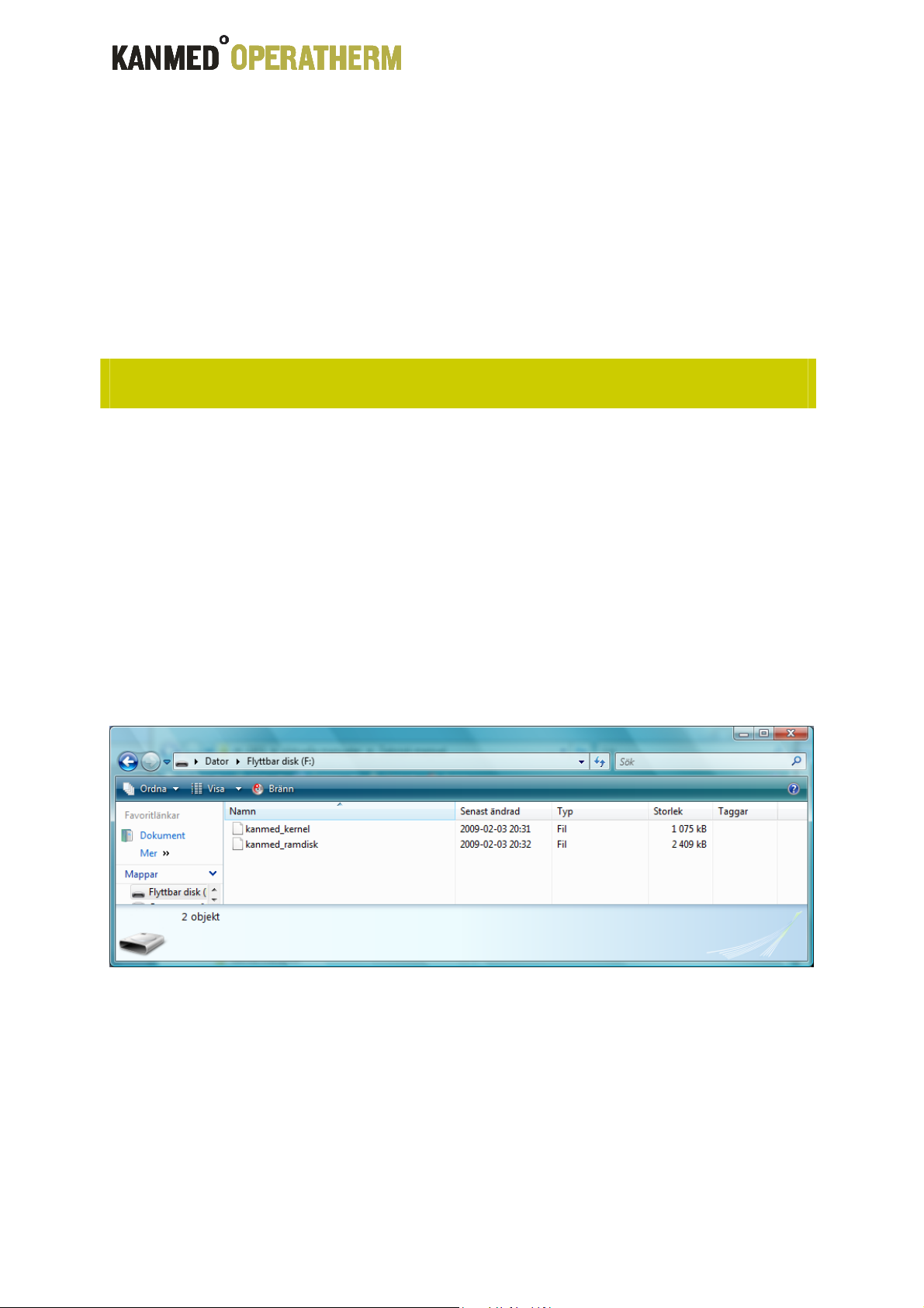
LOADING SOFTWARE TO THE CU. ................................................................................................................... 10
MENU functions .......................................................................................................................................... 12
Main Menu ............................................................................................................................................................... 12
System Settings ........................................................................................................................................................ 12
Set Time and date ..................................................................................................................................................... 12
Set Identifier............................................................................................................................................................. 12
Writing Logs to USB................................................................................................................................................ 13
Technical Data menu................................................................................................................................................ 16
Control Unit Summary ............................................................................................................................................. 16
Control Unit Calibration Data .................................................................................................................................. 16
Heating Pad Data Summary ..................................................................................................................................... 17
Heating Pad Calibration Data ................................................................................................................................... 17
System Measurements .............................................................................................................................................. 17
Control Unit Calibration Check................................................................................................................................ 18
Log Data Menu......................................................................................................................................................... 18
Control Unit Log ...................................................................................................................................................... 18
PAD Log .................................................................................................................................................................. 19
Special operation, workshop level only!................................................................................................................... 20
Control Unit RE-Calibration .................................................................................................................................... 20
8TROUBLE SHOOTING.......................................................................................................................... 21
Function Supervision and Alarms ............................................................................................................................ 21
Alerts ........................................................................................................................................................................ 21
Medium severity alarms ........................................................................................................................................... 22
High severity alarms................................................................................................................................................. 23
9ANNUAL CHECK OF THE SYSTEM.................................................................................................... 25
10 REPAIR INSTRUCTIONS OP3 CONTROL UNIT AND PAD............................................................. 26
CU Disassembling instructions: ............................................................................................................................... 26
CU Assembling instructions:.................................................................................................................................... 29
PAD Disassembling instructions: ............................................................................................................................. 30
11 WARRANTY........................................................................................................................................... 31
12 DISPOSAL............................................................................................................................................. 31
13 EMC COMPATIBILITY STATEMENT............................................................................................... 32
EMC Guidelines for the Operatherm OP3 system....................................................................................... 32

Technical manual KANMED Operatherm OP3
Page 3 of 34
Technical Manual
1 INTENDED USE
The KANMED Operatherm OP3 patient warming system is designed to be used pre-, per- and post
operatively. It must be used according to this manual. The system is intended to reduce the risk of
hypothermia. It is not intended for home use. It may only be operated by qualified medical staff
that has undergone proper product training according to the hospital routine.
Only KanMed original parts can be used with this system.
All other use will jeopardise the system function and the safety of the patient.
Latest version of the user manual and information about accessories can be found at
www.Kanmed.se
2 EXPLANATION OF SYMBOLS USED
(Green LED) Mains Power indicator
Increase temperature, or change
highlighted selection in MENU
Start/Stop button
Decrease temperature, or change
highlighted selection in MENU
(Red/Orange LED) Error Indicator
MENU
Select main MENU, or change
highlighted selection in MENU
Alarm Silence
Select alternative display mode,
or change highlighted selection in
MENU
Please read the instruction manual
ENTER, select highlighted item in
MENU.
Risk of explosion in the presence of
inflammable gases.
Earth potential equalisation
connection point
Safety class BF, Defibrillator safe
IPX7 Water tight Heating Pad
Fulfils MDD93/42/ECC. (Notified Body 0413= Intertek Semko AB, Sweden)

Technical manual KANMED Operatherm OP3
Page 4 of 34
3 SAFETY INFORMATION
Please refer to the safety information found in the User Manual for hazards related to
normal operation of the system.
Warnings
•System Malfunction. If the Operatherm OP3 self test does not perform correctly or the function
supervision has displayed an alarm or error message or the Control Unit has received mechanical damage,
it must be examined by a qualified technician before being used. If the Operatherm OP3 is suspected to not
operating properly, immediately consult a qualified technician for advice.
•Electrical Hazard The system must always be connected to a mains power outlet with proper protective
grounding. Always remove the mains power cable before cleaning the Control Unit. NOTE: The OP3 may
not be interfaced with any other electrical system. If this is done a new “system” is created per definition,
and the safety classification of the OP3 may be effected.
•Dropped or otherwise possibly damaged. If the Operatherm OP3 Control Unit had fallen to the floor or
has been subjected to other possible damage it must be examined by a technician before being used.
•Always remove mains power when the control unit is opened!
•Always perform internal work with the system in an ESD-protected environment.
Caution
•Modifications. Un-authorised personnel are not allowed to open the Control Unit or the Heating Pad
Connector. No modifications of the system, of any kind, are allowed since it will void the safety certification
of the system and may seriously endanger patient safety. Only original parts may be used. The Heating
Pad cable may not be altered in length or repaired in any way. If damaged, the complete Heating Pad must
be replaced.
•Compatibility. Only KANMED OP3 series Heating Pads can be used with Operatherm OP3 Control Unit. The
Operatherm OP3 system is NOT compatible with KANMED OP200 series Heating Pads.
•EMC. Operatherm OP3 needs to be installed and put into service according to the EMC information
provided. (Detailed EMC information can be downloaded from www.Kanmed.se)
•DIATHERMY equipment and Defibrillators. Under normal circumstances the Operatherm OP3 is not
disturbed by this type of equipment. However, if the diathermy or defibrillation is set at very high output
levels, the Operatherm OP3 might go into alarm state. In such a case, restart the system and observe that
the self test is being performed correctly. Note that the Control Unit housing is electrically connected to
earth.
•ECG disturbance. Under unfavourable conditions there is a risk that interference may occur on ECG
traces. This may occur if the ECG electrodes are not being applied strictly to the manufactures instructions
or if the Operatherm OP3 Heating Pad is positioned upside down (text side facing down).
•MRI cameras. The system is not designed for use with MRI cameras.
•Heating Pad storage. The Heating Pad should be stored using the Pad Hanger for wall mount that is
included in all control unit deliveries or rolled to a diameter not less than 150mm. Do not bend or fold the
Heating Pad in a way that sharp crease arises.
•Cleaning. Users should not use cleaning or decontamination methods different from those recommended
by Kanmed without first checking with Kanmed that the proposed methods will not damage the equipment.

Technical manual KANMED Operatherm OP3
Page 5 of 34
4 CLEANING, CHECKS BEFORE USE AND MAINTENANCE
Cleaning / Disinfecting
Always unplug mains power cord before any maintenance procedure. Wipe off the Control Unit with
a moist cloth and if necessary use normal hospital cleaning agent.
Clean the watertight Heating Pad with soap or your usual cleaning agent. Disinfect the Pad with
alcohol or any other commonly used disinfectant.
NOTE: Do not autoclave the Pad. Do not submerge the connector in any liquid.
Checks before use
Check that all parts are clean and in god condition. Check that the unit performs a correct self test
at start. If error codes appear and can not be eliminated with the suggestions given in the trouble
shooting section of this document, then it should be notified to Technical staff. Note: If any part of
the system has received mechanical damage, it should always be checked and correct system
function verified by technical staff.
Maintenance
Kanmed Operatherm OP3 does not require any special maintenance apart from what is described in
the technical section of the user manual.
Storage The Heating Pad shall be stored hanging with the Pad Hanger or lying flat. Avoid folding.
5 ACCESSORIES
Article no.
Product Comment
OP3-022 Control Unit Includes Pad Hanger, mains cord and instruction manual.
Factory set to 220-240V AC, 50/60 Hz
OP3-115 Control Unit As above, but set to 100-120 AC, 50/60 Hz
OP3-100 Control Unit As above, but set to 100V AC, 50/60 Hz
OP3-104 104 cm Heating Pad
1040 x 450 mm. 8 elements, 200W. X-Ray translucent.
Standard Heating Pad. Fits most patients. Requires two
standard Gel Pads.
OP3-150 150 cm Heating Pad 1500 x 450 mm. 8 elements, 200W. X-Ray translucent.
Requires three standard Gel Pads.
OP3-063 63 cm Short Heating
Pad
630 x 430 mm. 4 elements, 100W. X-Ray translucent.
Must always be used with the Gel Pad no GE-436315. For
small children during surgery, post operative warming,
under radiant heaters, on resuscitation tables.
OP3-050 50 cm Small
Heating Pad
500 x 300 mm. 4 elements, 100W. X-Ray translucent.
Must always be used with the Gel Pad no GE-305020. For
small children during surgery, post operative warming,
under radiant heaters, on resuscitation tables and in baby
cribs.
GE-455015 Gel Pad 500 x 450 x 13 mm. Standard Gel Pad.
GE-305015 Gel Pad 320 x 5550 x 15 mm. Fits perfectly over Heating Pad OP3-
050. Equipped with a pocket for the Heating Pad
GE-436315 Gel Pad 630 x 430 x 13 mm. Fits perfectly over Heating Pad OP3-
063.
OP3-005 Pad Hanger Wall mounted hanger for the Heating Pads.
OP3-050 User manual * English.
OP3-064 Service Manual English.
OP3-099 Calibration Adapter For checking the Control Unit calibration.
OP3-100 USB Memory stick Used for log dumps and for software update.

Technical manual KANMED Operatherm OP3
Page 6 of 34
SPARE PARTS
Article no.
Product Comment
700-0751 Rubber Frame NOTE: Two pcs per unit is required.
700-0766 Rear label
700-0748 PAD Connector
casing Plastic pad-connector housing (top/bottom) incl. screws.
700-0765 CU Front label
300-001 CPU unit incl front (OP303-1 Display and Computer board)
300-002 Main board (Op303-2)
300-003 Power board (OP303-3)
300-004 Power transformer (the large power transformer, 2 x 28,6 V 300 VA)
300-005 Power transformer (electronics power supply transformer, 10,3 V 9 VA)
300-006 Mains power intake With RF filter
300-007 Connector Saver 37 pin F/F
300-008 CU Rear panel excl. label
300-011 Cable kit Internal control unit cable kit
300-012 CU Handle
300-013 CU Bottom plate
300-014 CU Cabinet (naked cabinet)
700-0255 Elastosil A07, 90ml Silicon based adhesive for fixing the rubber frames.
OP303-1, Display and computer board OP303-2, Main board
OP303-3, Power board Cabinet assembly

Technical manual KANMED Operatherm OP3
Page 7 of 34
OP3-099 Calibration
Adapter
6 Technical Information
General
The Control Unit contains a microprocessor based heating control system that regulates the
temperature of each of the 8 elements (heating zones) of the Heating Pad. The temperature is
continuously monitored and the calculated average temperature of the heating pad is displayed.
The safety system in the Control Unit is continuously monitoring the main power, internal voltages,
running parameters, the pad condition and the behaviour of each element.
Two autonomous safety circuits, totally independent of the microprocessor based operating system,
can at any time stop the warming, should conditions occur that can cause over temperature.
If a fault is detected, the Control Unit will alarm visually and acoustically and switch off the
heating. The type of error is indicated on the alarm display. A description of the error codes are
found under the chapter “Trouble Shooting”.
Detailed system description.
The Operatherm OP3 system is designed with multiple level of protection against any foreseeable
errors that may cause potentially harmful conditions for the patient. The system is computer
controlled, with a fail safe (twin state) watch-dog, monitoring the correct operation of the main
process and will cause a safety relay to break the power to the pad if a computer error occurs. The
computer constantly monitors the running state of all vital parts of the system, and will
immediately report an error if any parameter runs outside its stated boundaries.
The calculated temperatures of the eight (or four) heating pad elements are based on individual
simultaneous measurement of the voltage and the current to each of the elements by two
independent A/D-converters. From these measurements the elements actual resistance is
calculated, and compared to the nominal resistance value programmed into the pads PROM
memory at calibration. The temperature coefficient of the element is also read from the PROM.
Based on this input, the elements current temperature is calculated (average value of the elements
area). Several comparative reference measurements are being performed in order to assure both
A/D converters integrity. If any discrepancy occurs, the system will break the power to the pad,
indicate the error and sound the alarm.
The measuring voltage fed to the pad is only 5V DC and one measuring slot is typically 10 ms long
(8.3 ms at 60 Hz). A full measuring/heating cycle is 18 pulses long, and 2 of these are always 5V
DC measuring pulses, leaving a maximum of 16 (of each 18) pulses available for heating.
The Pad element heating voltage is unregulated rectified 28V AC (typically), generating one
hundred pulses per second (one hundred and twenty at 60Hz mains voltage). Eight individual
temperature protected semi conductor switches, with built in error supervision, are being used to
gate the required number of heating pulses to each of the eight elements. (This regulating method
gives the ability to a linear individual control of the heating power to each of the elements from 0.1
to 23.0 W). Maximum power is however only permitted during 10 minutes from start. After this
time-out, the system will limit the output to maximum 11 heating pulses in each 18 pulse cycle,
(corresponding to max. 16 W/element).

Technical manual KANMED Operatherm OP3
Page 8 of 34
The heating current is fed via a safety relay, and any errors in the system will cause the safety
relay to break the current.
Apart from a constant on-line supervision of the systems vital safety functions, the system will
automatically turn into a cyclic self test mode for a couple of seconds every 15 min. and perform
an full off-line test of the safety circuits, among other thing turning the safety relay on and off, in
order to verify its integrity.
The Pad is connected to the control unit using a high grade 37 pin D-sub connector (extra thick
gold plating), with a female-female gender changer permanently mounted on the control unit. The
major connector-wear will take part in the female side of the connector, giving the ability to
periodically change the worn part. In the connector, the outermost 2+2 pins are exclusively used
as a safety loop, controlling the safety relay, to guarantee good connection of any intermediate
connectors used for the measuring circuits. Feeding voltage is fed on different pins than the
measuring circuit, reducing the risk of measurement errors. The common Pad feeding current is fed
over eight parallel pins for minimum connector load. All input/output connections are short-circuit
proof.
The Pads connector contains a independent micro processor with the dedicated task of monitoring
the pad feeding voltage at all time, and will break the safety loop if the heating current to any of
the eight elements are more frequent than normally anticipated (>16 of 18 heating pulses) or if
the unit is feeding more energy than 22,5 kWs over a period of 30 minutes (corresponds to 13,9 W
average power output during 30 minutes) to any of the elements. This function will safeguard
against any major short circuit in the control unit, (causing uncontrolled power feed to any, or all,
of the elements), or a temperature calculating error.
Both the control unit and the pad will automatically log events and running parameters into
memory when they are operated, enabling post-analyses to be made of any suspected system
malfunction.

Technical manual KANMED Operatherm OP3
Page 9 of 34
7 TECHNICAL DATA
Control Unit Art. no: OP3-022
Voltage Internally selectable;
100 V AC, 110-120 V AC, 220-240 V AC
Frequency 50/60 Hz
Power consumption 285 VA (max)
Temperature range 33°C to 39°C in steps of 1°C Temperature
accuracy Better than ±1°C
Resolution 1°C (Display resolution 0.1°C)
Over-temperature alarm level 41.0°C ±0.5°C
Dimensions L 255 mm, W 150 mm, H 120 mm.
Weight 6 kg
Mode of operation Continuous
Common for all Heating Pads
Voltage 30 V DC
Length of cable 2900 mm
Water protection Watertight, except for connector
Surface, electrical properties Not electrical conductive
Heating Pad Standard (104cm) Art. no: OP3-104
No. of elements: 8
Max Power 200 W (8 x 25 W)
Dimension L 1040 mm, W 450mm, H 3 mm
Weight 2 kg
Heating Pad Long (150cm) Art. no: OP3-150
No. of elements: 8
Power 200 Watt (8 x 25W)
Dimension L 1500 mm, W 450 mm, H 3 mm
Weight 2 kg
Heating Pad Short (63cm) Art. no: OP3-063
No. of elements: 4
Power 100 W (4 x 25W)
Dimension L 630 mm, W 430 mm, H 3 mm
Weight 1,6 kg
Heating Pad small (50cm) Art. no: OP3-050
No. of elements: 4
Power 100 W (4 x 25W)
Dimension L 500 mm, W 300 mm, H 3 mm
Weight 1,4 kg
Heating up time
Elements inside the Heating Pad about 8-10 minutes from 20°C to 37°C
Heating Pad surface about 25 minutes from 20°C when tested under
conditions of “ADEQUATE HEAT DISCHARGE”
in (IEC601-2-35)
Environment
Operating temperature +15°C to + 40°C
Shipping and storage - 20°C to + 60°C
Humidity 10% to 85% RH non condensing
Safety Standards EN60601-1, EN60601-1-2, IEC60601-2-35
Protection type BF, Defibrillator safe
Protection class Class I
MDD classification Class IIb
Expected lifetimes
Control unit OP3. Kanmed warrants a safe lifetime for Control unit OP3 of 10 years from first day of use. This is
under the condition that the unit has been serviced according to the user and or service manual and that the
unit has not been modified or changed in any way or for any reason.
Heating Pad. Heating Pads are consumable products and the expected lifetime is one to two years depending
how they are handled and how often they are used

Technical manual KANMED Operatherm OP3
Page 10 of 34
Classifications
The complete KanMed Operatherm OP3 system, International GMDN code: 37329, category 04.
The Control Unit assembly is classified as an Active Therapeutic Class IIb product (since it is designed
to be actively heating the body of a patient), according to Rule No. 9 of LVFS:2001:6
Product classification 6§ and appendix 9. International GMDN code: 36955, category 04.
The heating pads are also considered to be Class IIb products according to Rule No. 9 of the same
LVFS document. International GMDN code: 11989, category 04.
8 SERVICE SOFTWARE
The Operatherm OP3 can be loaded with different Software versions. The Customer version (with
blue bottom bar) is the only version allowed to be used in normal operation. The system function
with the Customer version of the software is described in the user manual. There is also a Service
SW version available (green bottom bar and the letter S after the version number) with extended
functionality. Below is a description of the technical menus and of the additional functions found in
the service software. Certain procedures, e.g. calibration check and log dump to USB etc. can also
be performed with the customer software version.
LOADING SOFTWARE TO THE CU.
NOTE 1: Before this operation is performed, make sure you have one Kanmed approved USB-
memory stick containing the latest version of the Service Software AND one additional Kanmed
approved USB-memory stick containing the latest version of the User Software (in order to re-load
the user software after the service session has been performed). The USB-memory must have the
two files “kanmed_kernel” and “kanmed_ramdisk” in the root level directory. Pls. note that the
Service Software and the Customer Software version have exactly the same file names (it is
therefore not possible to identify the software type only by the file name).
NOTE 2: When re-loading the user software back into the control unit, perform exactly the same
procedure as described below.
1. Disconnect the mains power. Turn the control unit up-side down and remove the bottom plate
(..mind the earth cable!). See disassembling instruction later in this document.

Technical manual KANMED Operatherm OP3
Page 11 of 34
2. Fit the USB-memory stick containing the Service Software
(..or the user software) into the internal USB connector.
3. Connect the mains power, and within 5 seconds, press and
hold left AND right arrow buttons pressed simultaneously
4. When the message “Updating SW..” is displayed, the left-
and right arrow buttons can be released.
The “Ok” message indicate that the new software has been
successfully loaded.
5. When the Stand-by screen is displayed, disconnect the
mains power and remove the USB-memory stick from the
Control unit. Reconnect the mains power and let the system
boot as normal. The new software has now been loaded into
the system.
The software type is identified by the version mark in the
bottom right corner of the display.

Technical manual KANMED Operatherm OP3
Page 12 of 34
MENU functions
These system functions is accessed if the “Menu” (up arrow) button is pressed when the unit is in
stand by mode. This menu or these functions are not available during normal operation of the
system. They are exclusively designed for system set-up or technical function control.
Main Menu
Top menu. Navigate by pressing the “up arrow” or “down
arrow” to highlight the desired action and press “enter”.
EXIT returns the system to stand-by mode.
NOTE:“up arrow” (menu) exits the function and returns the system to stand-by mode.
System Settings
Navigate by pressing the “up arrow” or “down arrow” to
highlight the desired action and press “enter”.
EXIT returns the system to the Main Menu.
NOTE:“up arrow” (menu) exits the function and returns the system to the Main Menu.
Set Time and date
Date will be set on the format YYYY-MM-DD and time on the 24
hour format HH-MM-SS.
Navigate by pressing the [‹] or [›] buttons to highlight the
desired digit to be changed and press “down arrow” to alter
the value of the digit.
“Enter” saves the new setting and returns the system to the
System Settings menu.
“Menu” (up arrow) ignores any change and returns the system
to the System Settings menu.
NOTE:“up arrow” (menu) exits the function and returns the system to the System Settings menu
without changing the time or date. Also available in the Customer Software version.
Set Identifier
A name of up to 10 characters can be given the unit (and will
be displayed in the bottom left corner of the screen).
Navigate by pressing the [‹] or [›] buttons to highlight the
desired position to be changed and press “down arrow” to alter
the character (A to Z _0 to 9)
“Enter” saves the new setting and returns the system to the
System Settings menu.
“Menu” (up arrow) ignores any change and returns the system
to the System Settings menu.
NOTE:“up arrow” (menu) exits the function and returns the system to the System Settings Menu
without changing the set name. Also available in the Customer Software version.

Technical manual KANMED Operatherm OP3
Page 13 of 34
Writing Logs to USB.
Note: This operation requires an empty Kanmed approved
USB-memory stick (<2 GB, FAT32 formatted). It can also be
performed with the Customer Software Version.
1. Fit the USB-memory stick into the internal USB connector.
2. Select Menu/Settings/Logs to USB. Press “Enter”
3. The message “WritingLogs” are displayed as long as the
writing process continues. Leave the system, it will normally
take a few minutes.
4. When the writing process is completed, the “WritingLogs”
message disappears. The USB stick can now be safely
removed.

Technical manual KANMED Operatherm OP3
Page 14 of 34
If no PAD is connected, three log files will be generated (above). Four if a PAD is connected
(below).
The log files are in txt format and can be opened with a text editor, e.g. WordPad or similar. The
log files are mainly intended for factory level post analyze of any “un-explainable” errors in the CU
or the PAD.
Data example from the CU-session log file D-OPERAT:
Log: 0
Start time: Fri Jul 11 14:26:03 2008
End Time: Fri Jul 11 14:26:16 2008
Time: 13
Total Time: 13 Sessions: 1
Pad: , Mode: 0
Energy: 0, Max Temp: 26.06, Min Temp: 24.78
Alarm: 55, Fri Jul 11 14:26:16 2008
Log: 1
Start time: Fri Jul 11 14:27:56 2008
End Time: Fri Jul 11 14:28:52 2008
Time: 56
Total Time: 69 Sessions: 2
Pad: , Mode: 0
Energy: 2, Max Temp: 29.60, Min Temp: 26.94
Alarm: 60, Fri Jul 11 14:28:52 2008
Etc.
Data example from the PAD log file P-“PAD S/N”:
Log: 0
time: Tue Sep 8 14:34:40 2009

Technical manual KANMED Operatherm OP3
Page 15 of 34
Max Temp: 38.31, Temp: 37.22
Log: 1
time: Tue Sep 8 14:33:40 2009
Max Temp: 34.66, Temp: 33.65
Log: 2
time: Tue Sep 8 14:32:39 2009
Max Temp: 30.40, Temp: 29.68
Log: 3
time: Mon Nov 24 14:55:28 2008
Max Temp: 41.85, Temp: 39.01
Log: 4
time: Mon Nov 24 14:54:28 2008
Max Temp: 41.85, Temp: 38.96
Etc.
Data example from the CU log file R-OPERAT:
Log: 0
Time: Tue Sep 8 14:35:21 2009
Pad: 00004
Desired Temp: 39, Temp: 39.39, Avg Temp: 32.65, Max Temp: 40.72
Log: 1
Time: Tue Sep 8 14:35:11 2009
Pad: 00004
Desired Temp: 39, Temp: 38.86, Avg Temp: 32.35, Max Temp: 40.31
Log: 2
Time: Tue Sep 8 14:35:01 2009
Pad: 00004
Desired Temp: 39, Temp: 38.32, Avg Temp: 32.04, Max Temp: 39.63
Log: 3
Time: Tue Sep 8 14:34:51 2009
Pad: 00004
Desired Temp: 39, Temp: 37.74, Avg Temp: 31.72, Max Temp: 39.02
Etc.
Data example from the file RL-OPERA (Note: normally a very large file!)
Log: 0
Time: Tue Sep 8 14:35:21 2009
Pad: 00004
Desired Temp: 39, Temp: 39.39, Avg Temp: 32.65, Max Temp: 40.72
DebugLog:
Pad: 2 CurTemp: 40.3127 R: 31.67 Po: 96
Pad: 3 CurTemp: 37.7483 R: 31.46 Po: 96
Pad: 4 CurTemp: 39.7063 R: 31.80 Po: 96
Pad: 5 CurTemp: 38.2161 R: 31.53 Po: 96
Pad: 6 CurTemp: 40.2193 R: 31.76 Po: 96
Pad: 7 CurTemp: 38.1843 R: 31.63 Po: 96
Pad: 0 CurTemp: 40.0399 R: 31.59 Po: 96
Pad: 1 CurTemp: 37.5327 R: 31.22 Po: 96
Pad: 2 CurTemp: 40.4759 R: 31.69 Po: 96
Pad: 3 CurTemp: 37.9906 R: 31.49 Po: 96
Pad: 4 CurTemp: 40.3586 R: 31.87 Po: 96
Pad: 5 CurTemp: 38.3338 R: 31.55 Po: 96
Pad: 6 CurTemp: 40.2193 R: 31.76 Po: 96
Pad: 7 CurTemp: 38.3397 R: 31.64 Po: 96

Technical manual KANMED Operatherm OP3
Page 16 of 34
Pad: 0 CurTemp: 40.1874 R: 31.61 Po: 96
Pad: 1 CurTemp: 37.8276 R: 31.26 Po: 96
Pad: 2 CurTemp: 40.5861 R: 31.70 Po: 96
Pad: 3 CurTemp: 38.1380 R: 31.51 Po: 96
Pad: 4 CurTemp: 40.3586 R: 31.87 Po: 96
Pad: 5 CurTemp: 38.5347 R: 31.57 Po: 96
Pad: 6 CurTemp: 40.4362 R: 31.79 Po: 96
Pad: 7 CurTemp: 38.4923 R: 31.66 Po: 96
Pad: 0 CurTemp: 40.2962 R: 31.62 Po: 96
Pad: 1 CurTemp: 37.9403 R: 31.27 Po: 96
Pad: 2 CurTemp: 40.7181 R: 31.72 Po: 96
Pad: 3 CurTemp: 38.3190 R: 31.53 Po: 96
Etc.
Technical Data menu
Several system functions can be monitored and controlled, e.g.
SW version data, calibration data etc. These functions are
exclusively designed for technical staff and maintenance
personnel.
NOTE:Also available in the Customer Software version.
Control Unit Summary
Information of SW version, Calibration information, Running
hours and No of system starts (operating sessions)
“Menu” (up arrow) returns the system to the Technical data
menu.
NOTE:Also available in the Customer Software version.
Control Unit Calibration Data
Factory set Calibration values for each of the 8 channels.
“Menu” (up arrow) returns the system to the Technical data
menu.
NOTE:The displayed values are proprietary system unique values. They can not be re-calculated to
corresponding resistance or similar values. This function is also available in the Customer Software
version.

Technical manual KANMED Operatherm OP3
Page 17 of 34
Heating Pad Data Summary
Information about the connected Pad. Pad serial number and
type, SW version, Calibration information, Running hours and
No of starts (operating sessions).
“Menu” (up arrow) returns the system to the Technical data
menu.
NOTE:Also available in the Customer Software version.
Heating Pad Calibration Data
Information about the connected Pad.
Factory set Calibration values for each of the 8 elements.
“Menu” (up arrow) returns the system to the Technical data
menu.
NOTE:The top value corresponds to the resistance measured for each individual element, at the
calibration temperature displayed as the bottom figure. This function is also available in the
Customer Software version.
System Measurements
This function measures each of the eight channels separately
for deep analyze of the system measurement accuracy and the
condition of each of the elements in the connected heating
pad.
Press the [‹] or [›] buttons to change the channel to study.
[v] (down arrow) changes to a screen where all 8 channels are
shown simultaneously.
“Menu” (up arrow) returns the system to the Technical data
menu.
NOTE:This is a function that is intended to analyze a Control unit’s ability to measure correctly on
each of the separate channels. If a Calibration Adapter is connected it shall measure the reference
resistance to a value better than 0,03 Ohm. It can also be used to measure the Heating Pad
resistance on each of the separate heating elements. This function is also available in the Customer
Software version.

Technical manual KANMED Operatherm OP3
Page 18 of 34
Control Unit Calibration Check
Note: This operation requires the use of a Calibration Adapter
(part No. OP3-099).
Connect the calibration adapter (part No: OP3-099) to the
control unit and press on/off. The unit will automatically enter
Calibration Check mode.
The unit will display the measured resistance for each of the 8
channels. Channel 3 – 6 will display two sets of figures. The
reason for this is that channel 1 – 6 is measured with A/D -
converter 1, and channel 3 – 8 with A/D-converter 2. Channel
3-6 will therefore show the readings from both converters.
After the unit has returned steady and reliable values (after 2-
5 min), the readings (the measured resistance for each
channel) should correspond to the adapters reference
resistance (displayed on top of the screen) within 0,03 ohm. If
the error is larger than this, it will display a red marking over
the reading, otherwise a green.
Press MENU to exit.
NOTE:If one or several of the readings exceeds 0.03 ohm, leave the unit running for at least 10-15
minutes and check again. If one (or several) of the reading is still just outside limits, pls. restart
the control unit and perform the test once more. If the error is consistent, the control unit might
need a re-calibration. This function is also available in the Customer Software version.
Log Data Menu
Select Main MENU/Log Data
NOTE: This function is also available in the Customer Software version.
Control Unit Log
Select “Control Unit Log” and press “Enter” to display the CU
logs. Press [<] or [>] to step through the different logs. Press
“MENU” to exit.
NOTE: This function is also available in the Customer Software version.

Technical manual KANMED Operatherm OP3
Page 19 of 34
PAD Log
Select “PAD Log” and press “Enter” to display the logs of the
connected PAD. Press [<] or [>] to step through the different
log pages. Press “MENU” to exit.
NOTE: The CU must first have been started in normal operation (performed a self test) with the
PAD connected in order to read these logs! This function is also available in the Customer Software
version.

Technical manual KANMED Operatherm OP3
Page 20 of 34
Special operation, workshop level only!
Control Unit RE-Calibration
Note: This operation requires two Calibration Adapters (part
No. OP3-099), and the special service SW-version 1.3S (or
newer).
Connect a calibration adapter (part No: OP3-099) to the
control unit and press on/off. The unit will automatically enter
Calibration Check mode.
After the unit has returned steady and reliable values (after 2-
5 min), indicated by the red or green markings of each of the
readings, the unit can be unlocked by pressing the key
sequence “left arrow”, “down arrow”, “right arrow” and “up
arrow”.
The system will display a “U” after the reference resistance
indicating that a calibration update process has been initiated.
Let the system measure for approximately 10 - 15 minutes and
the system will then automatically prompt for the second
calibration adapter to be inserted
(note: two separate adapters are mandatory for a control unit
re-calibration).
Approximately 5 minutes after the second adapter has been
fitted the verification process is finished, and the system
returns steady values (indicated by the red or green markings
of each of the readings), the readings (the calculated
resistance for each channel) should correspond to the adapters
reference resistance within 0,025 ohm.
“Enter” writes the new calibration values to the CU,
MENU exits without changing the values.
WARNING: This procedure may only be performed by Kanmed factory or by a Kanmed certified
workshop! CU re-calibration should NEVER be performed in field. Furthermore, the cu unit must be
in thermal balance before the procedure is performed, i.e. it should be in operating temperature.
The calibration adapters must also be room tempered (approx 21 deg C).
Failing in this procedure will/might jeopardize the operation of the system and can in worst case
result in the overheating of a patient.
Table of contents
Other Kanmed Medical Equipment manuals