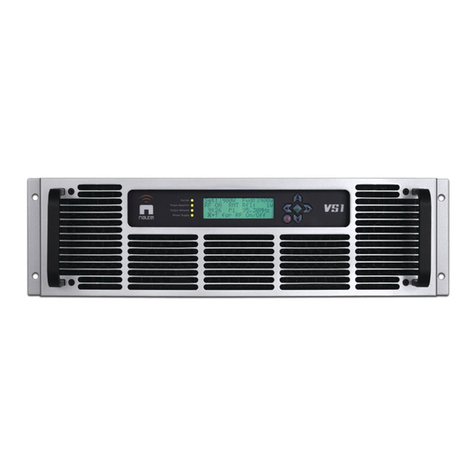
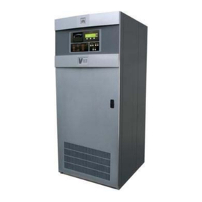
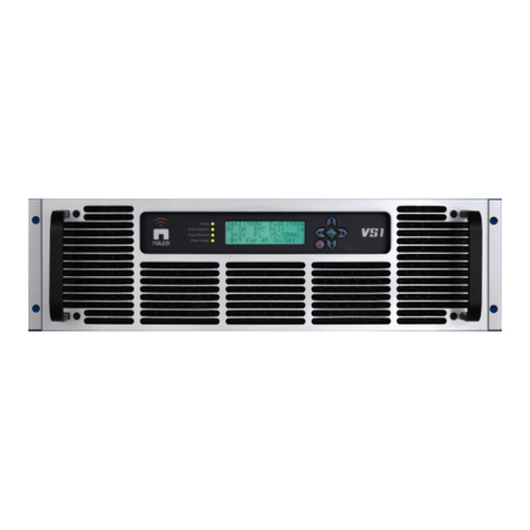
Nautel VS1 User manual

VS1 Transmitter
Installation Manual
Document:NHB-VS1-INS
Issue: 10.0 2018-10-29
Status: Standard


Nautel Limited
10089 Peggy’s Cove Road
Hackett’s Cove, NS Canada B3Z 3J4
Phone: +1.902.823.3900 or
Toll Free: +1.877.6NAUTEL (6628835) (Canada & USA only)
Fax: +1.902.823.3183
Nautel Inc.
201 Target Industrial Circle
Bangor, Maine USA 04401
Phone: +1.207.947.8200
Fax: +1.207.947.3693
Customer Service (24 hour support)
+1.877.628.8353 (Canada & USA only)
+1.902.823.5100 (International)
Email: [email protected]
Web: www.nautel.com
The comparisons and other information provided in this document
have been prepared in good faith based on publicly available
information. The reader is encouraged to consult the respective
manufacturer's most recent published data for verification.
© Copyright 2018 NAUTEL. All rights reserved.


VS1 Installation Manual Table of contents
Page v
Contents
Release control record vii
Preparing for installation 1-1
Mounting the transmitter 2-1
Connecting to station reference ground 3-1
Installing the RF feed line 4-1
Connecting ac power 5-1
Installing program inputs 6-1
Planning 6-1
Connecting cables 6-1
Installing control and monitoring wiring 7-1
Planning 7-1
Connecting cables 7-1
Commissioning 8-1
Pre-Commissioning 8-2
Commissioning 8-3
Network Setup 8-7
Changing the OS Password 8-9

VS1 Installation Manual
Page vi Issue 10.0 2018-10-29
Parts and tools 9-1
Contacting Nautel 9-1
Parts supplied by Nautel 9-2
Parts not supplied by Nautel 9-2
Parts ordering 9-2
Module replacement program 9-3
Tools for installation 9-3
Pre-installation / Installation assistance 10-1
Pre-installation consulting 10-1
Installation and commissioning service 10-1
Online documentation 10-3
On-site support 10-3
Training 10-4
Standard warranty 10-5
Extended warranties 10-8
List of terms 11-1

VS1 Installation Manual
Issue 10.0 2018-10-29 Page vii
Release control record
Issue Date Reason
10.0 2018-10-29 Hardware Release 10 (NARF65I and NARF65I/01).
Supports software version VS SW 5.2 and higher.

VS1 Installation Manual
Page viii Issue 10.0 2018-10-29

VS1 Installation Manual Preparing for installation
Issue 10.0 2018-10-29 Page 1-1
Section 1: Preparing for installation
Before installing your VS1 transmitter, perform the following steps:
1. Ensure that you have performed the pre-installation tasks described in the
VS1 Pre-installation Manual.
2. Inspect the shipping box for damage. Report any damage immediately to your Nautel sales
representative and the carrier.
3. Unpack the box. Remove all items from packing and place them on a suitable work area.
Check your packing list to make sure that you received all the components, including the
VS1, VS1 Quick Start Guide, VS1 USB device (contains technical manual set and
unpacking/installation video), installation kit and ancillary kit.
4. Assemble your parts and tools. For a list of required tools, see “Parts and tools” on page 9-1.
5. When you are ready to install the VS1 transmitter, follow the steps shown in Figure 1.1 on
page 1-2.
TIP When you have completed a task or step, put a check mark beside the step
number.
Note:
The VS1 Quick Start Guide provides a more streamlined method to unpack, install and
commission your transmitter. If you used the Quick Start Guide to successfully commission your
transmitter, Nautel recommends you use the information in this Installation Manual to verify
your installation or for more in-depth information, as required.
CAUTION:
FAILURE TO COMPLY WITH RECOMMENDATIONS MAY VOID YOUR MANUFACTURER’S
WARRANTY. FOR MORE INFORMATION, REVIEW YOUR WARRANTY DOCUMENTS.

VS1 Installation Manual Preparing for installation
Page 1-2 Issue 10.0 2018-10-29
Figure 1.1: Flowchart - Installing the transmitter
Mounting the transmitter - see page 2-1
Connecting to station reference ground - see page 3-1
Installing control and monitoring wiring - see page 7-1
Commissioning - see page 8-1
Perform operational tasks:
“Commissioning” and “Going On-Air”, beginning on page 8-3
Installing the RF feed line - see page 4-1
Installing program inputs - see page 6-1
Connecting ac power - see page 5-1

VS1 Installation Manual Mounting the transmitter
Issue 10.0 2018-10-29 Page 2-1
Section 2: Mounting the transmitter
To mount the VS1 transmitter in a cabinet, refer to the following installation aids provided with the
VS1 transmitter:
• Unpacking/Installation Video (IS15009, located on the USB device that also contains the
technical documentation suite): step-by-step video that shows how to unpack your VS1 and
properly mount it in a cabinet.
• VS1 Quick Start Guide: full-colour foldout guide that provides instructions to install the VS1
in a cabinet and achieve on-air operation
Note:
Unless otherwise specified, all hardware referenced in the Unpacking/Installation video or the
VS1 Quick Start Guide is included in the VS1’s installation kit (Nautel Part # 211-8978-
05).

VS1 Installation Manual Mounting the transmitter
Page 2-2 Issue 10.0 2018-10-29

VS1 Installation Manual Connecting to station reference ground
Issue 10.0 2018-10-29 Page 3-1
Section 3: Connecting to station reference
ground
To connect to the station reference ground, perform the following steps:
See Figure 3.1 on page 3-2 as an installation guide.
1. Locate the VS1’s safety ground stud (E1) on the rear panel of the VS1.
2. Attach a continuous, low impedance copper conductor (minimum 3/4” braid) between the
station reference ground and safety ground stud E1. Ensure the station reference ground
conductor is at least 3 mm (1/8 in) from the exterior of the transmitter or host cabinet.
3. For information about grounding the lightning protection, see the VS1 Pre-Installation
Manual.
For detailed information about lightning protection, see the Recommendations for Transmitter Site
Preparation manual, available from your Nautel sales agent, or online from the Nautel website.
4. Firmly tighten all hardware.
Note:
The VS1 Quick Start Guide provides a more streamlined method to unpack, install and
commission your transmitter. If you used the Quick Start Guide to successfully commission your
transmitter, Nautel recommends you use the information in this Installation Manual to verify
your installation or for more in-depth information, as required.
CAUTION:
It is important that the conductor attached to E1 does not contact the transmitter
chassis or host cabinet at any other point.

VS1 Installation Manual Connecting to station reference ground
Page 3-2 Issue 10.0 2018-10-29
Figure 3.1: Station Reference Ground Strap Connection
E1
(1/4” threaded
stud)
IMPORTANT !
Do not allow conductor to contact the
transmitter or host cabinet chassis at any other point.
From Station
Reference Ground
Conductor
(copper braid shown)
PARTIAL REAR VIEW OF VS1

VS1 Installation Manual Installing the RF feed line
Issue 10.0 2018-10-29 Page 4-1
Section 4: Installing the RF feed line
Prepare and install an RF feed coaxial line as follows:
1. Connect the VS1’s RF output to a dummy load, if available, during the commissioning
procedure's initial turn on. If the RF feed line is not connected to a switching circuit that
permits antenna/dummy load selection, connect the RF feed line for the dummy load to the
transmitter's RF output until transmitter commissioning is complete.
2. Verify the RF feed line to the antenna system is in place and is cut to the required length. Do
not install the feed line’s mating connector (7/8-inch EIA or 7/16 DIN) at this point.
3. Obtain one or two ferrite toroids (Nautel Part # LP23, 85.7 mm) from the ancillary kit.
Install the ferrite toroid(s) on the VS1 end of the RF feed line. If practical, the RF feed line
should pass through a minimum of two times (one turn) (see Figure 4.1).
Note:
The VS1 Quick Start Guide provides a more streamlined method to unpack, install and
commission your transmitter. If you used the Quick Start Guide to successfully commission your
transmitter, Nautel recommends you use the information in this Installation Manual to verify
your installation or for more in-depth information, as required.
Note:
Nautel recommends that you perform the commissioning procedure in Section 8, “Commissioning”
before connecting the transmitter to its antenna system.
Note:
The VS1’s RF output connector is a 7/8-inch EIA connector or 7/16 DIN connector, which is
user-specified.

VS1 Installation Manual Installing the RF feed line
Page 4-2 Issue 10.0 2018-10-29
Figure 4.1: Routing RF Feed Line Through Ferrite Toroid
4. Install the appropriate size connector (7/8-inch EIA or 7/16 DIN) on the RF feed line.
5. Mate the RF feed line's connector to the RF OUT (J2) connector on the rear of the VS1.

VS1 Installation Manual Connecting ac power
Issue 10.0 2018-10-29 Page 5-1
Section 5: Connecting ac power
To connect ac power to the transmitter, perform the following steps:
1. Switch off the ac power at the service entrance.
2. Obtain the ac power cord (Nautel Part # JN57) and two 85.7 mm ferrite toroids (Nautel Part
# LP23) from the installation kit.
3. Pass the ac power cord through the ferrite toroids. If practical, the ac power cord should pass
through a minimum of two times (two turns).
4. Connect the ac power cord to the AC INPUT receptacle (U1) on the rear of the VS1.
5. Connect the other end of the ac power cord to the 200 to 240 V ac input source.
6. Verify that the station reference ground is connected to the safety ground stud at the rear of
the VS1.
Note:
The VS1 Quick Start Guide provides a more streamlined method to unpack, install and
commission your transmitter. If you used the Quick Start Guide to successfully commission your
transmitter, Nautel recommends you use the information in this Installation Manual to verify
your installation or for more in-depth information, as required.

VS1 Installation Manual Connecting ac power
Page 5-2 Issue 10.0 2018-10-29

VS1 Installation Manual Installing program inputs
Issue 10.0 2018-10-29 Page 6-1
Section 6: Installing program inputs
This section describes how to connect program input wiring to the VS1.
Planning
Make sure you have read and fully understood the program input options described in the VS1 Pre-
installation Manual before proceeding. The VS1 Pre-installation Manual also includes the connector type
and gender (male or female) of the transmitter’s interfacing connectors.
Connecting cables
1. Obtain a ferrite toroid [85.7 mm (Nautel Part # LP23) or 38 mm (Nautel part # LXP38), as
appropriate] from the Installation Kit.
2. Route program input cable(s) through the ferrite toroid, then to the rear of the VS1. If
practical, pass the cable through the ferrite toroid twice (two turns).
3. Connect the appropriate program input cable(s) between the program source(s) and the
connector(s) described in “Analog inputs” or “Digital inputs” in the VS1 Pre-installation
Manual (see Figure 6.1 on page 6-2).
Note:
The VS1 Quick Start Guide provides a more streamlined method to unpack, install and
commission your transmitter. If you used the Quick Start Guide to successfully commission your
transmitter, Nautel recommends you use the information in this Installation Manual to verify
your installation or for more in-depth information, as required.
Note:
With the exception of D-sub connectors, all program input mating connectors must be provided by
the user.

VS1 Installation Manual Installing program inputs
Page 6-2 Issue 10.0 2018-10-29
Figure 6.1: Program Input Connections
VS1 TRANSMITTER REAR VIEW
NOTE: D-Sub mating connectors are provided in the ancillary
kit. Other connector types must be provided by the user.
Other manuals for VS1
5
Table of contents
Other Nautel Transmitter manuals

Nautel
Nautel VS1 User manual
Nautel
Nautel XL12 Owner's manual

Nautel
Nautel NX50 User manual
Nautel
Nautel VS300 User manual

Nautel
Nautel NV5LT Programming manual

Nautel
Nautel NX5 User manual

Nautel
Nautel NV30LT-N Manual

Nautel
Nautel J1000 Operating instructions

Nautel
Nautel ND500II User manual

Nautel
Nautel VX150 Manual

Nautel
Nautel J1000 Operating instructions

Nautel
Nautel ND500II-113-x21 User manual

Nautel
Nautel GV10 Programming manual

Nautel
Nautel GV30N Programming manual

Nautel
Nautel NV10LT User manual

Nautel
Nautel XR12 User manual

Nautel
Nautel NX5 AM Manual
Nautel
Nautel XR12 Programming manual
Nautel
Nautel XR3 User manual

Nautel
Nautel NV30 User manual