Sensorex TX2000 User manual
1
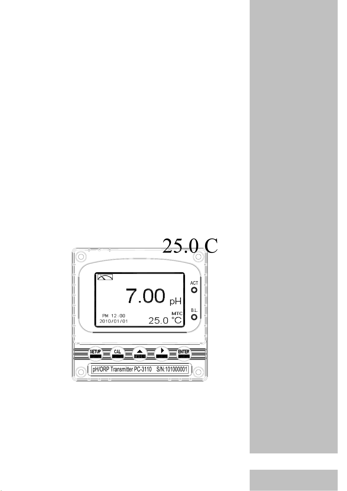
TX2000
Intelligent
pH/ORP
Transmitter
25.0 C
Operation
Manual
www.GlobalTestSupply.com
Find Quality Products Online at: sales@GlobalTestSupply.com

Precautions for installation
Wrong wiring will lead to breakdown or electrical shock of the instrument, please read this
operation manual clearly before installation.
zMake sure to remove AC power from the controller before wiring input, output connections,
and remove it before opening the controller housing.
zThe installation site of the controller should be good in ventilation and avoid direct sunshine.
zThe material of signal cable should be special coaxial cable. Strongly recommend using our
coaxial cable. Do not use normal wires instead.
zAvoid electrical surge when using power. Especially when using three-phase power, use
ground wire correctly.
zThe internal relay contact of the instruments is for alarm or control function. Due to safety,
please must connect to external relay which can stand enough ampere to make sure the safety
operation of the instruments.(Please refer to chapter 3.7“Illustration of electrical
connection")
www.GlobalTestSupply.com
Find Quality Products Online at: sales@GlobalTestSupply.com
www.GlobalTestSupply.com
Find Quality Products Online at: sales@GlobalTestSupply.com

6.4 Multi-point calibration(Multi-Cal) 22
6.5 Temperature 23
6.6 Relay 1 24
6.7 Relay 2 25
6.8 Wash time(Clean) 26
6.9 Analog output 1 (pH/ORP) 27
6.10 Analog output 2 (temperature) 28
6.11 Date/Time (Clock) 29
6.12 Sample average of measurements (Digital filter) 30
6.13 Backlight settings 31
6.14 Contrast settings 32
6.15 Automatically back to measurement mode(Return) 33
7. Calibration
Block diagram of Calibration 34
7.1 Entry of calibration menu 35
7.2 Security password of calibration 36
7.3 Automatically back to measurement mode(Return) 37
7.4 pH calibration 38
7.4.1 TECH mode (Up to 3-point calibration) 38
7.4.2 NIST mode (Up to 3-point calibration) 38
7.4.3 Asymmetry mode (Up to 3-point calibration) 38
7.4.4 Definition of calibration parameter 39
7.4.5 TECH, NIST buffer Calibration 40
7.4.6 Any Calibration 41
7.5 ORP calibration 42
8. Error messages (Error code) 43
9. Maintenance 44
Appendix 45
www.GlobalTestSupply.com
Find Quality Products Online at: sales@GlobalTestSupply.com
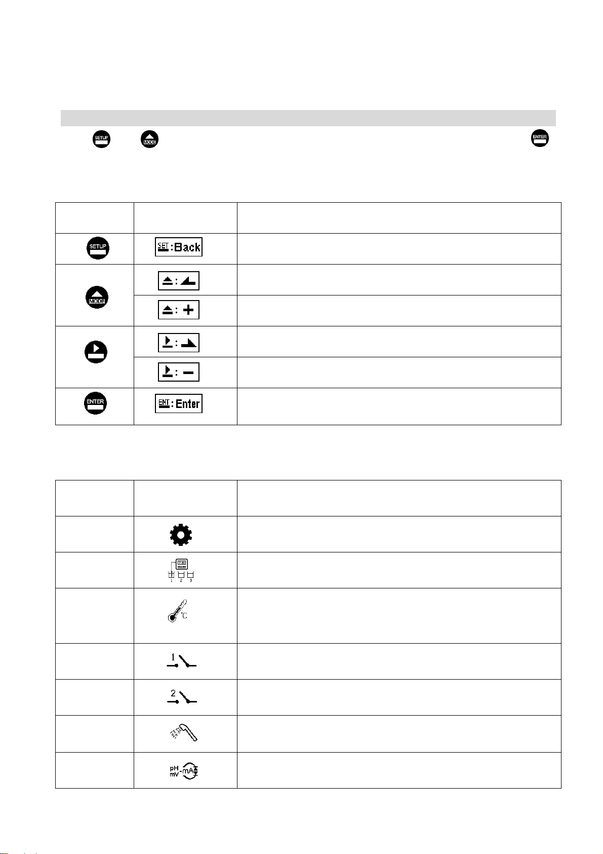
Brief Instruction
Description of set-up settings (see chapter 7 for details)
Press and simultaneously to see the overview of the set-up settings now. Then press I
if you would like to modify set-up settings. Press keypad according to index of keypad on the screen.
Index of keypad
keypad Function Description
Back to upper layer
Choose change to left page
Increase digit
Choose change to right page
Decrease digit
Confirm settings after modifications and then go through next
step
Selection of set-up items
keypad Accordingly item Description
Mode Measurement mode, to choose pH or ORP measurement
Multi-Cal. Multi-point calibration, to choose 1, 2, or 3 points calibration
Temperature Temperature measurement and compensation, including MTC,
PTC, NTC (3 types total). MTC---Manual temperature
compensation, PTC/NTC--- auto temperature compensation
Relay 1 First relay setting, to choose action off or Hi/Lo alarm
Relay 2 Second relay setting, to choose action off or Hi/Lo alarm
Clean Automatic wash time setting, to choose electrode cleaning
equipment’s ON and OFF duration
Analog 1 Current output according to pH or ORP setting range
1
www.GlobalTestSupply.com
Find Quality Products Online at: sales@GlobalTestSupply.com

Analog 2 Current output according for temperature
Clock Clock setting (When power LVORVW, theLQVWUXPHQW¶V
time setting will return to the factory VHWWLQJ
Back-light Backlight setting, to set Auto/ON/OFF backlight, brightness,
and sensitivity
Contrast Contrast of screen setting
Digital Filter Take every serial 1~60 measurements, average them
continuously, and make it as the readings
Return Return to the measurement mode
Code Security code of set-up mode. The factory default is 1111, and a
designated user can change the code.
2
www.GlobalTestSupply.com
Find Quality Products Online at: sales@GlobalTestSupply.com

Description of calibration settings (see chapter 8 for details)
Press and simultaneously to see the last calibration information. Then press if
to make a new calibration or modify setting of calibration. Press keypad according to
index of keypad on the screen.
Index of keypad:
keypad Function Description
Back to upper layer
Change to left page
Increase digit
Change to right page
Decrease digit
Confirm settings after modifications and then go through next
step
Selection of calibration items (up to three-point calibration)
keypad Function Description
Code Security code of calibration mode. The factory default is 1100.
Return Time interval setting of returning to the measurement mode
TECH Use tech buffer as standard solution for calibration
NIST Use NIST standard buffers(DIN 19266) as standard solution for
calibration
Any Use any buffer solution by users’ definition for calibration
Note
Sensorex reserves the right to change the figure of icons and contents. The actual icons and contents
please refer to the instruments.
3
www.GlobalTestSupply.com
Find Quality Products Online at: sales@GlobalTestSupply.com
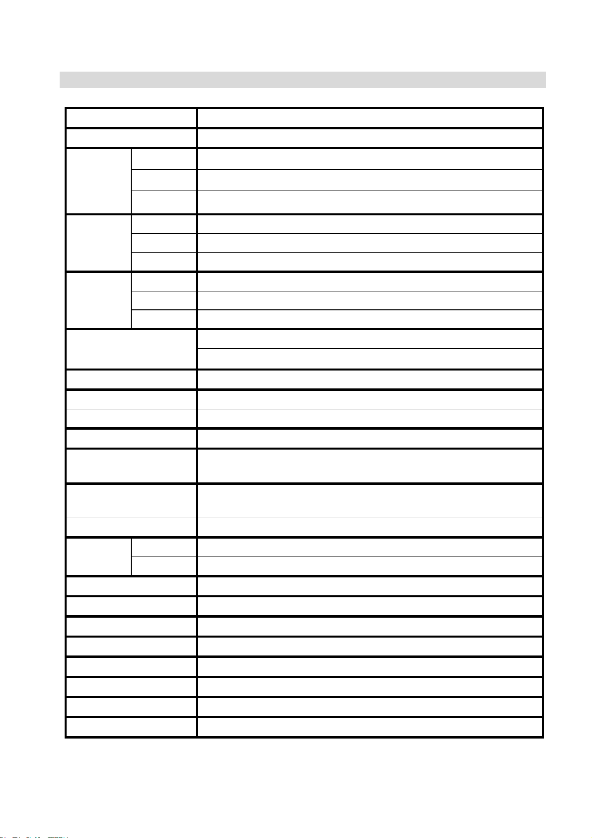
1. Specifications
Model TX2000
Measuring modes pH / ORP / Temp.
pH -2.00~16.00 pH
ORP -1999~1999 mV
Ranges
Temp. -30.0~130.0 °C
pH 0.01 pH
ORP 1 mV
Resolutions
Temp. 0.1 °C
pH ±0.01 pH ±1 Digit
ORP ±0.1% ±1 Digit
Accuracy
Temp. ±0.2°C±1 Digit
NTC30K/ PT 1000 auto temperature compensation
Temperature
Compensation Manual adjustment temperature compensation
Calibration mode Tech.、NIST.、Asymmetry mode, up to three point calibration
Ambient Temp. 0~50°C
Storage Temp. -20~70°C
Input Impedance > 1012 Ω
Display Large LCD display with environment light sensor
auto/manual illumination function
Analog output 1 Isolated DC 0/4~20mA corresponding to main measurement,
max. load 500Ω
Analog output 2 Isolated DC 0/4~20mA corresponding to Temp., max. load 500Ω
Contact RELAY contact,240VAC 0.5A Max.(recommend)
Settings Activate Two sets of individual HIGH or LOW programmable control
Wash RELAY contact: ON 0~99min. 59sec. / OFF 0~999hr 59min.
Voltage Output DC±12V,1W max.
Certification IP65
Power Supply 100V~240VAC±10%,4W max.,50/60Hz
Installation Wall or Pipe or Panel Mounting
Dimensions 96m × 96mm × 132mm (H×W×D)
Cut off Dimensions 93 mm ×93 mm (H×W)
Weight 0.5Kg
Note: The specifications are subject to change without notice.
4
www.GlobalTestSupply.com
Find Quality Products Online at: sales@GlobalTestSupply.com

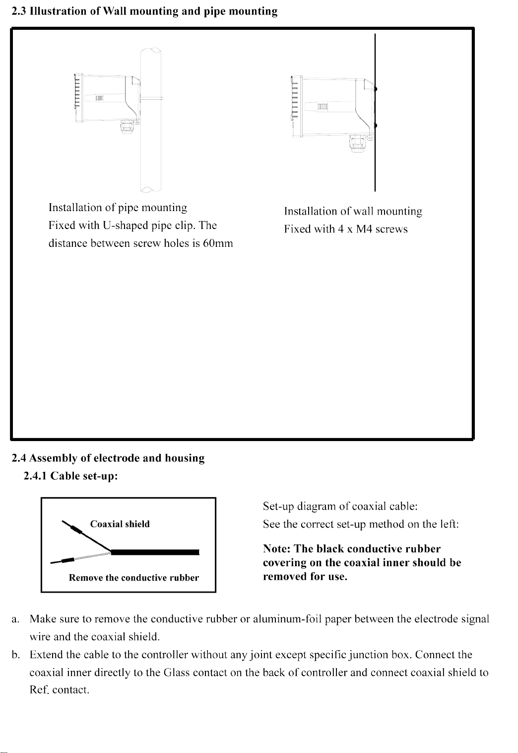
2. Assembly and installation
2.1 Transmitter installation: This Transmitter can be installed through panel mounting, wall
mounting and pipe mounting.
Panel mounting: First, prepare a square hole of 93 x 93mm on the panel box,
and then insert the controller directly into the panel box. Insert the mounting bracket
from the rear, until it is locked into the pickup groove.
2.2 Illustration of panel mounting:
93 mm
93 mm
Hole size
87 mm
+
87 mm
Hole distances on the panel box
Mounting bracket
Illustration of panel mounting,
fixed with mounting bracket
+
++
112 mm
5
www.GlobalTestSupply.com
Find Quality Products Online at: sales@GlobalTestSupply.com
www.GlobalTestSupply.com
Find Quality Products Online at: sales@GlobalTestSupply.com

This page
intentionally
left blank
www.GlobalTestSupply.com
Find Quality Products Online at: sales@GlobalTestSupply.com

This page
intentionally left
blank
www.GlobalTestSupply.com
Find Quality Products Online at: sales@GlobalTestSupply.com

This page
intentionally
left blank
www.GlobalTestSupply.com
Find Quality Products Online at: sales@GlobalTestSupply.com
www.GlobalTestSupply.com
Find Quality Products Online at: sales@GlobalTestSupply.com
www.GlobalTestSupply.com
Find Quality Products Online at: sales@GlobalTestSupply.com

This page
intentionally left
blank
www.GlobalTestSupply.com
Find Quality Products Online at: sales@GlobalTestSupply.com

This page
intentionally left
blank
www.GlobalTestSupply.com
Find Quality Products Online at: sales@GlobalTestSupply.com
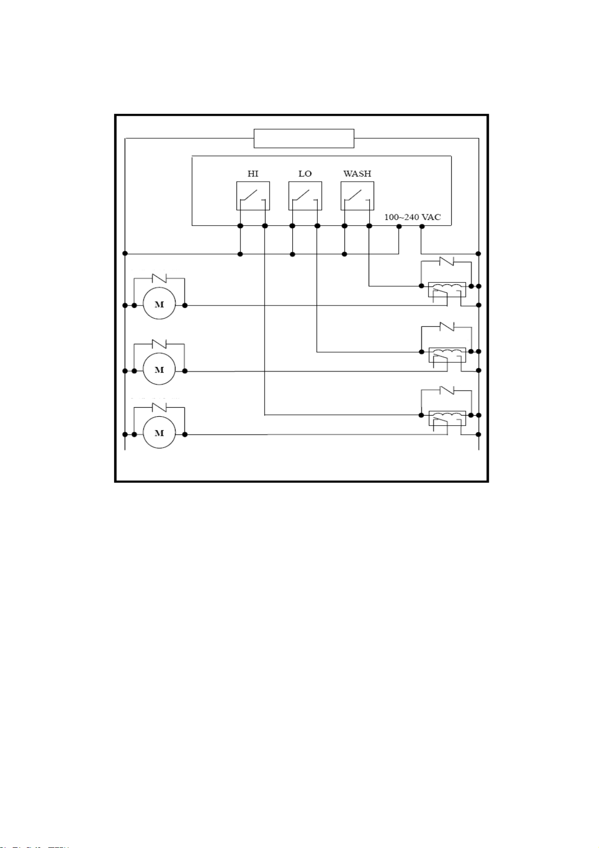
3.7 Illustration of electrical connection:
Surge absorber
Surge absorber
Surge absorber
Surge absorber
Transmitter
Washing device
Dose feeder
Dose feeder
100 ~ 240VAC
Surge absorber
Surge absorber
External relay
External relay
External relay
14
www.GlobalTestSupply.com
Find Quality Products Online at: sales@GlobalTestSupply.com
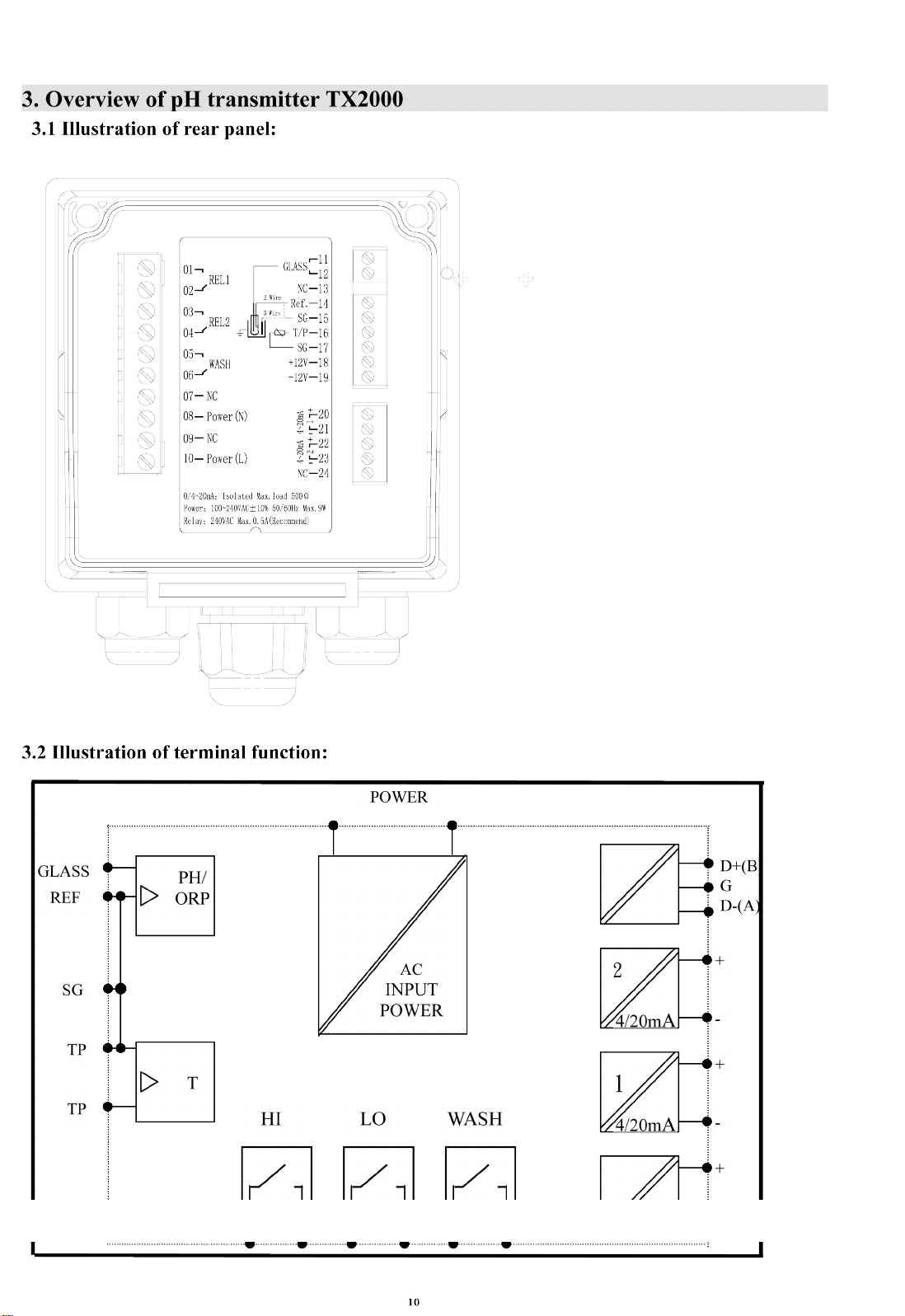
4. Configuration:
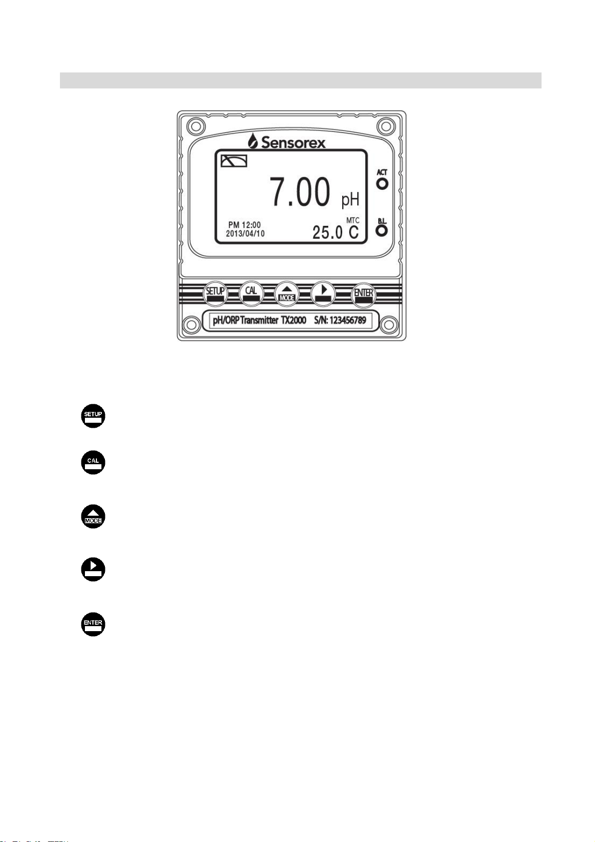
4.1 Illustration of front panel:
4.2 Keypad:
In order to prevent inappropriate operation by others, before the parameter setting and
calibration, the operation applies multi-keys, and coding protection if necessary . Description of
the key functions is in the following:
:In the parameter set-up mode, pressing this key allows you exit parameter set-up mode
and return back to Measurement mode.
: In the Calibration mode, pressing this key allows you exit Calibration mode and return
back to Measurement mode.
:1. In the parameter set-up mode and Calibration mode, press this key to select
left change or to go to another page.
2. When adjusting value, press this key to increase the value.
:1. In the parameter set-up mode and Calibration mode, pressing this key to select
right change or to go to another page.
2. When adjusting value, press this key to decrease the value.
:Key for confirmation; pressing this key is essential when modifying data value or
selecting the parameter setting items in the window.
4.3 LED indicators:
ACT:Washing device operation indicator and controlling operation indicator (Relay 1、Relay 2)
B.L. : Light sensor; in the automatic display backlit mode, the lamp will light or go out as the
change of environmental brightness.
15
www.GlobalTestSupply.com
Find Quality Products Online at: sales@GlobalTestSupply.com

4.4 Display:
Note: 1. When the wash device is turned on, the display shows and flashes the description, “Clean
Running”. At the same time, the ACT indicator LED lights up, and the transmitter
automatically turns off Relay 1 and Relay 2 function. After finishing cleaning, the Relay 1
and Relay 2 will automatically back to normal status.
2. When Relay 1 which is set in high setting point is in action, the display shows and flashes
the description, “REL 1_Hi”, and ACT indicator LED lights up. When Relay 1 which is set
in low setting point is in action, the display shows and twinkles the description, “REL 1_Lo”,
and ACT indicator LED lights up.
3.When Relay 2 which is set in high setting point is in action, the display shows and flashes
the description, “REL 2_Hi”, and ACT indicator LED lights up. When Relay 2 which is set
in low setting point is in action, the display shows and flashes the description, “REL 2_Lo”,
and ACT indicator LED lights up.
4. When under measurement mode, if the temperature compensation mode is set in MTC
(Manual adjustment), press or to adjust the MTC temperature manual.
Analog 2 output
current over range
alarm
Control function
on hold
:Measurement mode
:Set-up mode
:Calibration mode
REL 1 high or
low point alarm
Wash device in
action condition
Measurement unit
Clock
REL 2 high or
low point alarm
Analog 1 output
current over range
alarm
Temperature
compensation mode
(MTC/ATC)
Temperature value
Measurement value
16
www.GlobalTestSupply.com
Find Quality Products Online at: sales@GlobalTestSupply.com
Other manuals for TX2000
2
Table of contents
Other Sensorex Transmitter manuals

Sensorex
Sensorex TX105 User manual

Sensorex
Sensorex CT-1000 User manual

Sensorex
Sensorex TX2000 User manual

Sensorex
Sensorex TX3100 User manual

Sensorex
Sensorex TX3000 User manual

Sensorex
Sensorex CX105 User manual

Sensorex
Sensorex TX2000 User manual

Sensorex
Sensorex CX100 User manual

Sensorex
Sensorex TX100 Specification sheet
Popular Transmitter manuals by other brands


Draper
Draper AUTOLINK TRIGGER-ER Installation

Ashcroft
Ashcroft XLDP1 operating instructions

HK Instruments
HK Instruments DPT-Priima Series installation instructions

MGC
MGC UDACT-300A Installation and operation manual supplement

Zenner
Zenner MinoConnect instruction manual

HK Instruments
HK Instruments CDT-MOD-2000 Series installation instructions