P2
Avvertenze - Getting Started
ATTENZIONE - WARNING:
CAUTION!
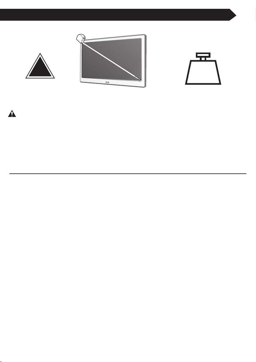
55””””
DIMENSIONE MASSIMA
MAXIMUM SCREEN SIZE
!
70”
60 kg
Non superare ma la portata massima per evitare danni a cose o persone! E'
responsabilità dell'installatore accertarsi che il peso del televisore (con relativi
accessori) non superi i 60 kg.
Exceeding the weight capacity can result in serious personal injury or damage to equipment! It
is the installer’s responsibility to make sure the weight of the TV (with accessories) does not
exceed 60 kg.
ATTENZIONE: UN'INSTALLAZIONE O UN ASSEMBLAGGIO ERRATI POSSONO PROVOCARE SERI DANNI A COSE O
PERSONE. LEGGETE LE SEGUENTI AVVERTENZE PRIMA DI INIZIARE.
Se non comprendete le istruzioni o avere dubbi o domande contattate un installatore qualificato.
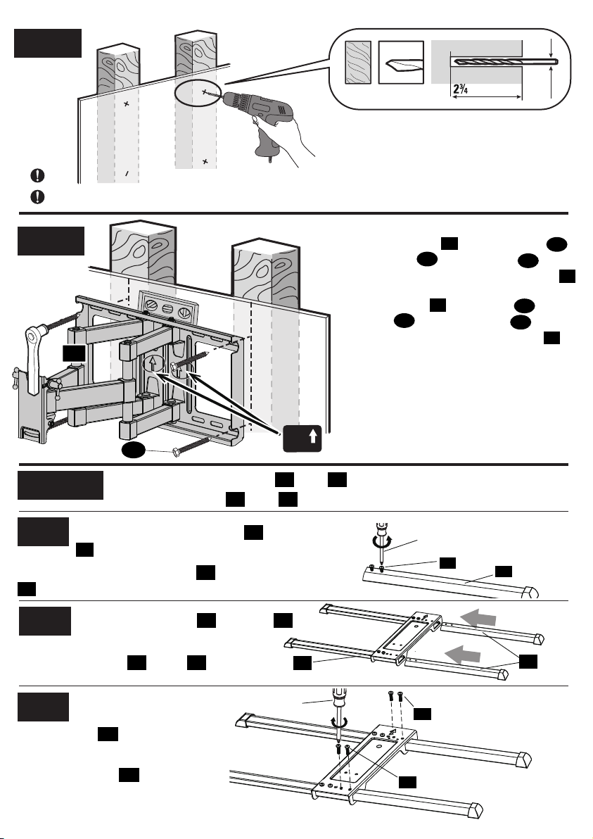
Non installate o montate se il prodotto o dei componenti sono danneggiati o mancanti. Non tutte le parti e gli strumenti inclusi devono
essere usati. Questo prodotto è stato progettato per essere usato su pareti verticali costruite su montanti in legno. Tali pareti
dovrebbero essere costituite da montanti con misura minima di 2"x 4" e spaziatura massima di 16", mentre lo spessore del rivestimento
della parete dovrebbe essere al massimo di 1/2" (cartongesso, intonaco, assicelle di legno). Per il montaggio rivolgetevi a personale
qualificato. Per un'installazione sicura il muro deve poter supportare un peso pari ad almeno 4 volte il carico totale. In caso contrario è
opportuno rinforzare la superficie. E' responsabilità dell'installatore verificare che la parete di fissaggio risponda a questi requisiti.
Questo prodotto può contenere parti mobili. Usare con cautela.
NON SUPERATE LA PORTATA MASSIMA DI PESO PER QUESTO PRODOTTO.
WARNING! SEVERE PERSONAL INJURY AND PROPERTY DAMAGE CAN RESULT FROM IMPROPER INSTALLATION OR
ASSEMBLY. READ THE FOLLOWING WARNINGS BEFORE BEGINNING.
If you do not understand the instructions or have any concerns or questions, please contact a qualified installer.
Do not install or assemble if the product or hardware is damaged or missing. Not all parts and hardware included must be used. If you
This product has been designed for use on a vertical wall constructed of wood studs. Wood studs being defined as a wall consisting of
a minimum of 2” x 4” studs with a maximum of 16” stud spacing with a maximum of 1/2” of wall covering (drywall, lath, plaster).For
custom installations please contact a qualified installer. For safe installation, the wall you are mounting to must support 4 times the
weight of the total load. If not, the surface must be reinforced to meet this standard. The installer is responsible for verifying that the
wall structure/surface will safely support the total load.
This product may contain moving parts. Use with caution.
DO NOT EXCEED THE MAXIMUM WEIGHT CAPACITY FOR THIS PRODUCT.
Please check www.perlegear.com for more products and company information.
CARICO MASSIMO
MAXIMUM WEIGHT CAPACITY