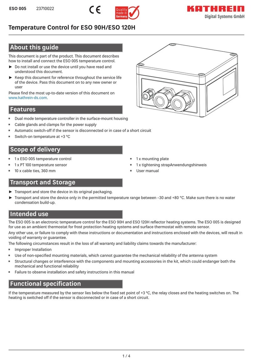
Kathrein ESO 99 S User manual

1 / 12
ESO 99 S 237500017
Weather-based temperature controller for heating of
reflectors and feed system holders
Features
About these instructions
This document is part of the product. These instructions
describe how to install and connect the ESO 99 S temperature
controller.
▶ Do not install and use the device until you have read and
understood this document.
▶ Keep this document for reference throughout the life of the
device. Pass this document on to any subsequent owners
and users.
The latest version of these instructions for use can be found on
our website: www.kathrein-ds.com
Items supplied
•1 x Controller with mounting plate
•1 x Sensor assembly
•1 x Earth strap clamp
•1 x Earth cable
•2 x Straps for mast diameter 70 - 90 mm
•10 x Cable ties 360 mm long
•4 x Caps M16
•1 x Cable gland M32 x 1.5
•English instructions for use
Transport and storage
▶ If possible, transport and store the temperature controller in
the original packaging.
▶ Store the temperature controller in a dry location and protect
it against mechanical damage.
The ESO 99 S is a temperature controller for ESO 120/124/180 H
and ESO 124/180 HL reflector heaters and ESO 126 and ESO 129
feed system holders. It prevents snow, ice and frost building up
on the reflector surface of the antennas:
•Automatic activation of the heating when the outside temper-
ature falls below 4° C and there is snow, ice, frost or water on
the reflector
•Electronic two-point controller with adjustable temperature
threshold for the heating pad
•With fastening strap for mast installation
•Excess temperature switch-o
•Less than 25% energy consumption compared to ESO 97 S
and ESO 97 SL controllers

2 / 12
Safety and installation instructions
WARNING!
When carrying out installation work in locations where there is a risk of falling, take appropriate safety
precautions, e.g. use of a working platform. Make sure that the roof is suciently strong and stable to carry
out the installation work (risk of damage or collapse). There is also a risk of serious injuries due to falling
parts.
Make sure that:
▶ The connected devices are disconnected from the power supply.
▶ The person carrying out the installation or repair does not suer from vertigo and can move around safely on the
roof.
▶ The person carrying out the installation or repair is wearing sturdy and non-slip footwear.
▶ The person carrying out the installation or repair has a secure position to stand and hold on while working.
▶ The roof and the climbing equipment used (e.g. ladder) are dry and non-slip.
▶ The roof can withstand the weight of the person carrying out the repairs.
▶ Nobody is below the antenna during installation/removal.
Installation and connection may only be performed by qualified specialist personnel.
To prevent hazards during installation and operation, the instructions and information provided must be strictly adhered to.
Proper installation and connection are prerequisites for compliance with the corresponding standards.
DANGER!
Risk of death due to electric shock in the event of contact with electrical equipment!
Correct performance of the installation and electrical connection is a crucial safety factor.
Observe the installation conditions and steps described as precisely as possible.
Modifications to the electrical installation may only be carried out by a specialist electrician. Do not make any modifica-
tions yourself.
Intended use
Do not use the ESO 99 S for any purposes other than that specified in these instructions. Any use other than that specified above will
invalidate the warranty or guarantee.
In particular, never:
•Modify any of the components.
•Use any components other than those explicitly specified by the manufacture for use with the ESO 99 S.
The ESO 99 S is used to control the ESO 120/124/180 H and ESO 124/180 HL reflector heaters and prevents snow, ice and frost from
building up on the antenna reflector surface. Any use other than that specified above will invalidate the warranty or guarantee.
The following circumstances result in the loss of all warranty and liability claims towards the manufacturer:
•Improper installation
•Use of non-specified fixing materials, which cannot guarantee mechanical stability
•Non-permitted use
•Structural changes or interference with the components and fixing accessories in the kit, which could jeopardise both the mechan-
ical stability and functional reliability
•Use of cleaners containing solvents, such as acetone, nitro-cellulose combination thinner, petrol etc.
•Failure to observe the installation and safety instructions in this manual

3 / 12
Functional description
Using the ESO 120/124/180 electric heaters prevents the build-up of snow, ice and frost on the antenna reflector surface, thus avoiding
faults with reception.
The control unit described in detail below performs the following tasks:
●Automatic activation of the heating in the event of snow, ice or frost build-up
●Automatic deactivation of the heating if the reflector temperature exceeds the set value
●Manual activation of the heating is possible (failure of sensors/electronics, test operation in summer)
●Operating condition display
●Potential-free indication of faults
Brief description of controller
All electrical components are located in a light, dust and moisture-proof polycarbonate housing.
When the housing cover is opened, all components are accessible with contact protection. The terminal strip connects all the
incoming and outgoing cables (sensors, heating, power supply) to the electrical components.
Operating mode: Automatic
The electronics switch on the power circuit if:
- The ambient temperature and heating temperature fall below the set value P(+4 °C SRR; factory setting: +40 °C ELTC-21), and
- The sensor electrodes detect moisture, snow, ice or frost on the antenna surface.
The heating switches o when one of the above conditions is no longer true. However, the integral timer function can be used to set
a post heating time between 1 and 10 min (factory setting: 5 min). The post heating time thus covers a short period during which the
sensor signal drops out, perhaps due to a brief burst of sunshine or to the influence of wind on one of the sensors. Pressing “POWER
OFF” resets the post heating time.
When the load circuit is activated, the operating RGB on the SRR lights up in yellow to indicate “AUTOMATIC HEATING ON”.
Operating mode: Manual
In “MANUAL” mode, the electronics are bypassed apart from the ELTC-21 function. The load circuit is switched on and the operating
RGB on the SRR flashes yellow to indicate “MANUAL HEATING ON”
Manual mode can also be activated using the remote operation signal (5 - 30 V). In “MANUAL” mode, if a sensor has a fault for
example, the heating continues running with temperature control using the ELTC-21 heating controller.
This enables the function of the heating to be checked during the summer months.

4 / 12
Functional description
Two electronic control units are installed in the ESO 99 S controller housing.
The frost controller (SRR) is used to detect the ambient conditions and the heating controller (ELTC-21) is used as a surface thermo-
stat with remote sensor for detecting the heating temperature. Cable glands and terminals are installed for the electrical connection.
SRR frost controller function (device 1)
The SRR frost controller detects the ambient temperature and also detects any frost, snow or ice build-up on the antenna surface.
PT100 sensors are used to detect the ambient temperature. The limit value is factory set to a fixed +4°C. Frost and potential ice build-
up are only expected at temperatures above this value. The coat forming on the monitored surface is registered using a 2-rod probe. A
window function in the SRR 200 enables the parameters to dierentiate between water and ice to be set.
These parameters are determined once and cannot be changed without the corresponding software.
If both conditions are met (temperature below +4°C and ice build-up detected), the heating controller is enabled by a potential-free
switching relay in the SRR 200 and heating of the antenna surface begins. As soon as one of the two conditions is no longer met,
the post heating time begins (the time is adjustable using potentiometers on the front panel of the SRR). The heating process is only
ended when the post heating time has elapsed. If the conditions are met again during the post heating time, the post heating time is
(automatically) reset and the control process starts again.
The heating controller keeps the antenna temperature at the set limit value (factory setting +40 °C). A control input allows the heating
controller to be enabled manually.
The USB port is used for communication with a computer. The frost controller can be set using the SRR 200 Config Tool parameter
setting software. Monitoring is also possible. The instructions for using this software can be found in the “SRR 200 Config Tool” oper-
ating manual.

5 / 12
SRR function status
LED Colour Condition Explanation
Status
LED
Green OK The ambient temperature is above the set limit value. No ice detected.
White Tempera-
ture The ambient temperature is below the set limit value. No ice detected.
Blue Ice The ambient temperature is below the set limit value. Ice detected.
Oper-
ating
LED
Green ON Device is switched on and ready for operation.
Red flashing
Alarm Sensor fault
Yellow Heating
Auto
Heating output ON due to current ambient conditions or active post
heating time.
Yellow
flashing
Heating
Manual
Heating output ON due to manual switching or active post heating
time.
ELTC 21 heating controller function (device 2):
If the actual value (P01) is lower than the setpoint (P10 minus hysteresis P11), the power relay switches on the heating. The integrated
alarm relay has a changeover contact that allows fault messages in the event of temperature too high / low, sensor failure or sensor
short circuit. In the event of sensor faults, the control relay switches the heating cable o or on depending on the controller configu-
ration. If the sensor fails or there is a sensor short circuit, the heating is switched o.
Operation is very easy. After switching on, the device type number (C-2) appears, followed around three seconds later by the meas-
ured actual value. Briefly pressing the “P” button displays “Set”, followed by the setpoint display, which automatically reverts after
5 seconds. Pressing the “P” button for around 3 seconds opens the parameter list “P10”. Holding down the “P” button for a further 3
seconds displays “dC” for degrees Celsius or “dF” for degrees Fahrenheit.
Parameters and their mean
H = Device 2 heating temperature
P01 Actual value on temperature sensor (number only)
P10 Controller setpoint, eective on relay 1, range P13...P14 [H +40 °C]
P11 Switching hysteresis of P10, range 2...10K, [H 2K]
P12 Minimum down time (relay K1); range 0...30 min, [5 min]
P13 Maximum permitted setpoint, range P14...+390 °C, [H +60 °C]
P14 Minimum permitted setpoint, range -50 °C...P13, [H -5 °C]
P20 Sensor type
0 = Pt100, 3-wire, °C (resolution 1K)
[1] = Pt100, 2-wire, °C (resolution 1K)
2 = Pt100, 3-wire, °F (resolution 2°F)
3 = Pt100, 2-wire, °F (resolution 2°F)
P21 Sensor correction -30...+10 K, [0]
P30 High temperature alarm, P31...400°C [60 °C]
P31 Low temperature alarm, -60...P30 [-60 °C]
P32 Alarm delay in operation, 0...99 min [0 min]
P33 Alarm delay after switch on, 0...500 min [0 min]

6 / 12
P34 Relay mode (power relay K1 and signal relay K2)
0 = Relay K2 (active) energised on sensor fault, power relay K1 de-energised on sensor fault
[1] = Relay K2 (passive) de-energised on sensor fault, power relay K1 de-energised on sensor fault
2 = K2 operates as release relay, power relay K1 de-energised on sensor fault
3 = Relay K2 (active) energised on sensor fault, power relay K1 energised on sensor fault
4 = Relay K2 (passive) de-energised on sensor fault, power relay K1 energised on sensor fault
5 = K2 operates as release relay, power relay K1 energised on sensor fault
P34=3, P34=4 and P34=5 is only permitted for frost protection applications and when using self-regulating heating cables.
The values in square brackets [...] represent the factory settings.
Release relay mode
In this mode (P34=2 and P34=5), relay K2 switches independently of P32 and P33 as soon as the actual value lies between P30 and
P31.
Alarm relay mode
(P34 = 0 or 1): If the actual temperature is below P31 when the device is started, P33 is used once as the alarm delay to give the system
more time. In normal operation, P32 is used as the alarm delay.
Commissioning
Reliable operation of the controller requires all components to be installed and started up properly taking
into account the warnings set out in these installation instructions.
Before starting the installation, check the material list to ensure that all parts have been supplied.
1. Use the installation instructions and circuit diagrams supplied to check that the installation is correct.
2. Before connecting the connecting cable in the controller housing, test the heating for continuity and insulation resistance (Ri)
(see installation instructions for the heating). These measurements (Ri) should be repeated after replacement of a defective
heating plate.
Heating functional test
1. Measure the mains input voltage: 230 VAC + 6/- 10%
2. Green “Status” and “Operation” LEDS light up
3. Set switch 1S1 to “Manual ON”
4. Yellow “Heating Manual” LED flashes
5. Measure the heating circuit voltage and heating circuit current at terminals X1: 1-10.
During this time, the ELTC-21 monitors the heating temperature.
Change the heating temperature setting on the ELTC-21 to +10°C.
The contactor 1K1 is de-energised.
Set the old value (+40 °C) and the contactor K1 is energised again.
After the measurement has been performed, set the switch 1S1 to the “Auto ON” position. The “Heating Manual” LED goes out after
the set post heating time
has elapsed.
Controller functional test
1. The “Status” and “Operation” LEDs on the SRR light up green
2. Cool down the ambient temperature sensor to below + 3°C using iced water or coolant spray.
The status LED must light up white for “Temperature”.
Touch the two rod electrodes with wet hands.
The status LED must now light up blue for “Ice”.
The operating LED must now light up yellow for “Heating Auto”.
The contactor 1K1 is energised and the operating hours counter must be running.
3. As soon as the “Ice” or “Temperature” condition is no longer met, the set post heating time (1 - 10 min) starts running. This value
can be changed on the potentiometer on the SRR using a screwdriver. When the post heating time has elapsed, the contactor 1K1
is de-energised.
4. Fault detection and signalling
- Disconnect the sensor cable from the “Ambient temperature” PT100. (Open the cable connection at terminal 3 on the SRR
control unit). The operating LED flashes red for “Alarm”.
- Disconnect the sensor cable from the “Reflector temperature” PT 100 (open the cable connection at terminal 17 on the ELTC-21
control unit). Fault signal E02 appears in the display.
For both faults, the alarm contact at terminal X1, 11 / 12 opens (closed circuit principle).

7 / 12
Installation and connection
Required tools and equipment
•Side cutters
•Long nose pliers
•Water pump pliers
•Flat-bladed screwdriver
•Coolant spray for functional test
•Hexagon socket wrench 5 mm
•Drill and metal drill bit ∅6.2 mm
Installing the temperature controller
1. Attach the straps supplied to the mounting plate as shown in the figure. The straps allow the controller to be attached to masts
with a diameter of 60 to 85 mm.
2. Attach the controller to the mast by tightening the slotted screws in the straps, so that all cable glands point downwards.
Control unit
Tensioning screw
Mounting plate
Tensioning strap
Antenna mast
Lid
Installing the sensor unit
•Drill a fixing hole ∅6.2 mm in the edge of the reflector
•
A
A
A-A
Front of the reflector
XCAS 120, CAS 124: X = 280 mm
CAS 180: X = 500 mm
•Remove the screw and washer (1) from the sensor unit and
loosen the screws (2 + 3) so that the unit can be moved in the
aluminium profile
•
1 2 3
4
Preparation

8 / 12
Installation
1. Pivot the sensor unit over the edge of the reflector (Fig. 1), guide the screw and washer (1) through the pre-drilled hole and screw
into the aluminium profile (Fig. 2) but do not tighten securely yet
Fig. 1
Fig. 2
2. Slide the aluminium profile up to the reflector plate and securely tighten the screw (1) (MA= 5 Nm) (Fig. 3).
3. Slide the sensor housing and plate in the aluminium profile until the ends of the two electrodes are located on the reflector
surface and under tension, then securely tighten the screws (2 + 3) again (MA= 5 Nm) (Fig. 4).
4. Securely tighten the cable tie (4) on the unit.
Fig. 3 Fig. 4

9 / 12
Electrical connection
Antenna mast
Tensioning strap
External temerature control
Feed in
Cable from the reector and
feed system support heating
1. Run the connecting cables for the heating pads, feed system
holder, heating sensor unit and heating pad temperature
sensor along the antenna support to the control unit and
secure with cable ties.
2. Feed the cables into the control unit / connection box from
below through the M16 cable glands (heating pads, feed
system holder heating) and M12 cable glands (temperature
sensors, sensor unit).
3. Feed the mains cable into the control unit through the M32/
M25 cable gland from below.
Before connecting the cables in the control unit, check
the heating for continuity and insulation resistance.
These measurements should also be performed after
replacement of a defective heater. Refer to the oper-
ating instructions for the corresponding reflector
heater for details.
4. The cables are connected as shown in the “Connection
diagram” on page 11.
Only connect the electrical system to the voltage spec-
ified on the rating plate. Non-compliance can destroy
the heating due to overheating or fire.
Connecting the earth clamp
The earth clamp is attached close to the terminal box on the reflector mast as follows:
1. Tension the strap around the mast. Make sure that the strap is securely attached to the antenna mast.
2. Pull the V2A strap through the clamp.
3. Tension the V2A strap with the tension screw.
4. Connect the earth cable to the earth strap clamp.
5. Feed the earth cable through an M12 cable gland in the terminal box.
6. Connect the earth cable to the earth terminal.
➯This guarantees earthing of the entire electrical system.
M12 3x M16 5x
M25

10 / 12
Maintenance recommendation
Controller
We recommend performing a regular complete functional test of the system, preferably before the onset of winter, to check that the
entire antenna heating system is operating correctly (see “Controller functional test” on page 6).
Sensor system
Once a year, preferably before the onset of winter, the sensors should be wiped over with a moist cloth to remove any heavy dirt.
Heating plates / heating pads
The heating plate or heating pad should be checked for damage at regular intervals to ensure they are in sound condition. Other than
this, the heaters are largely maintenance free once installed.
Technical data
Mechanical data
Housing material: Polycarbonate
Dimensions: 360 x 254 x 165 mm
Weight: 5.3 kg
Cable inlets: 3 x M12, 5 x M16, 1 x M32/M25
Permissible ambient temperature: -30° to +60° C
Recommended
installation temperature: +5° to +20° C
Protection class: IP66
Electrical data
Operating voltage: 230 V~, +6 %/-10 %, 50/60 Hz
Breaking capacity: 16 A
Alarm contact: 8 A / 230 V
Temperature measuring input: 2 x PT 100 temperature
sensor
Moisture measuring input: 2 rod probe
Activation temperature U: +4° C (SRR factory setting)
Setpoint temperature H: +40° C (ELTC-21 P10 factory
setting)
Adjustment range max. U: -10° to +30° C (SRR)
Adjustment range max. H: -5° to +60° C (ELTC-21 P13/P14)
Display range /
resolution: -50° to +400° C / 1K (ELTC-21)
Type of control: Two-point controller
Repair and replacement
KATHREIN Digital Systems GmbH
Customer Service
Eiselauerweg 13
89081 Ulm, Germany
Phone: +49 731 270-909 70
E-mail: [email protected]
Business hours (CET):
Mon-Thu: 8:00–12:00 and 12:45–17:00
Fri. 08:00 -13:00

11 / 12
Connection diagram
L
230 V 50 Hz
Absicherung 10 A
RCD 30 mA verwenden
NPE. 6
1U3
Über-
temp.
10
17
1R2
1
2
PT 100
11
ELTC-21
18
230 VAC
SC00099S
Witterungsgeführte
Steuerung
K2
6
5
4
8
K1
9
1U1
Reif-
regler
16
3
1R1
PT 100
1
2
PT 100
12
SRR 200
2
230 VAC
K2
Alarm
15EL
GND
65
14
13
10
K1
11
ESO 180 HL
ESO 180 H
Optional:
ESO 90 H
ESO 120 H
ESO 124 H
X1
1
E1
1
E1
2
4
3
E1
4 5
E1
PE
6 7
E1
8
ESO 126 / ESO 129
Beheizung für Speisesystem-Halterungen
9
E1
10 PE. 2 PE. 3 PE. 4 PE. 5
PE. 1
Fühler
Heizungstemperatur
ESO 124 HL
1
NST 255
2-Stabsonde
EL
rosa
GND
grau
22
21
132
131
X1
Alarm
Ruhestromprinzip
im Fehlerfall
geönet
Fernwirkkontakt
manuell Ein
5-30V
weiss
grün
braun
1K1
A1
A2
Heizung
1S1
1
2
Hand
Ein
1K1
1
2
.5
1 2.6
111
112
122
121
11322
21
102
101
-X1

www.kathrein-ds.com | support@kathrein-ds.com 936500099/b/A4/STM/1121/DE | Subject to amendment.
KATHREIN Digital Systems GmbH | Anton-Kathrein-Str. 1–3 | 83022 Rosenheim | Germany | Phone +49 731 270 909 70
For your notes
Electronic equipment
Electronic equipment must not be disposed of in domestic waste. According to directive 2012/19/EU OF THE EUROPEAN
PARLIAMENT AND COUNCIL of 04 July 2012 on waste electrical and electronic equipment, it must be disposed of profes-
sionally. At the end of its service life, take this unit to a designated public collection point for disposal.
Disposal
This manual suits for next models
1
Table of contents
Other Kathrein Temperature Controllers manuals