KAUP T 416H User manual

SAP 100081
en
Operating Manual
Original Operating Manual
1
Edition 06/17
Subject to modifications
Drum Tippling Clamp
T 416H, T 406H
T 416U, T 406U
T 416 2H, T 406 2H
T 416 2U, T 406 2U
T 416H
T 416U
Drum Tippling clamp with sideshift and one-sided hydraulic drive, suited
to be used for moving 1 cylindrical steel drums.
T 406H
T 406U
Drum Tippling Clamp without sideshift and one-sided hydraulic drive,
suited to be used for moving 1 cylindrical steel drums.
T 416 2H
T 416 2U
Drum Tippling clamp with sideshift and two-sided hydraulic drive, suited to
be used for moving 1 cylindrical steel drums.
T 406 2H
T 406 2U
Drum Tippling Clamp without sideshift and two-sided hydraulic drive,
suited to be used for moving 1 cylindrical steel drums.

Operating Manual
2
Original Operating Manual
Contents Page
1. Introduction ............................................................................................................................................. 4
1.1 Working with this manual......................................................................................................... 4
1.2 Warning notes and symbols..................................................................................................... 4
1.3 Copyright.................................................................................................................................. 4
1.4 CE-Mark................................................................................................................................... 5
1.5 Qualified and authorised personnel ......................................................................................... 5
1.6 Warranty claims based on defects........................................................................................... 5
1.7 Limits of applicable use............................................................................................................ 5
2. Safety aspects......................................................................................................................................... 6
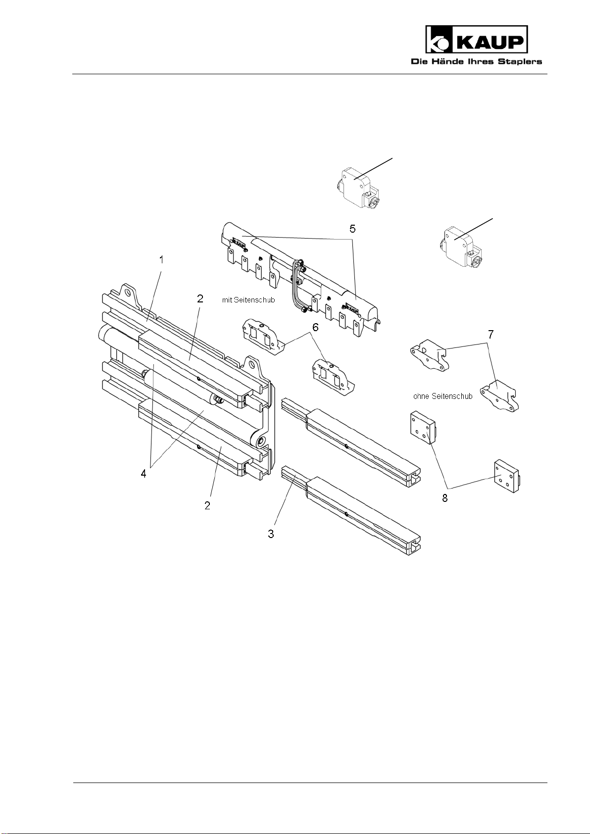
3. Design ...................................................................................................................................................... 7
3.1 Clamp with mounting................................................................................................................ 7
3.2 Drum Tippling Arms ................................................................................................................. 8
3.2.1 Hydraulically tilting by 180°.......................................................................................... 8
3.2.2 Hydraulically tilting by 90°............................................................................................ 9
3.2.3 Mechanisch endlos drehbar......................................................................................... 9
3.3 Efficient equipment settings on electric vehicles ................................................................... 10
3.4 Proper use of the equipment.................................................................................................. 10
3.5 Improper use.......................................................................................................................... 11
4. Installation and checking out .............................................................................................................. 11
4.1 Installation.............................................................................................................................. 11
4.1.1 Mounting attachment with quick release bottom hooks............................................. 13
4.1.2 Installation / Uninstallation screw-on forks................................................................. 13
4.2 Checking out .......................................................................................................................... 13
4.2.1 Bleeding the hydraulic system ................................................................................... 14
4.2.2 Adjustment after putting into service.......................................................................... 14
5. Operation ............................................................................................................................................... 15
5.1 General................................................................................................................................... 15
5.2 Load handling......................................................................................................................... 15
5.3 Driving.................................................................................................................................... 16
5.4 Tip .......................................................................................................................................... 16

Operating Manual
Original Operating Manual
3
6. Maintenance and servicing...................................................................................................................16
6.1 General ...................................................................................................................................16
6.2 Significant modification...........................................................................................................18
6.3 Schedule for routine maintenance and lubricants ..................................................................18
6.3.1 Clamp..........................................................................................................................19
6.3.2 Mounting (with or without sideshift) ............................................................................19
6.3.3 Drum tippling clamp arm, hydraulically tilting by 180°................................................23
6.3.4 Drum tippling clamp arm, hydraulically tilting by 90°..................................................24
6.3.5 Drum tippling clamp arm, mechanically rotating.........................................................25
6.3.6 Identification plate and caution board.........................................................................27
7. Troubleshooting.....................................................................................................................................28
8. Disposal..................................................................................................................................................30
9. Transport ................................................................................................................................................30
10. Decommissioning and storage ............................................................................................................31
11. Spare parts list (not part of the Operating Manual) ...............................................................................31
12. EC Declaration of Conformity (Summary)...........................................................................................31
Our service department in Aschaffenburg will be happy to answer your technical questions and to provide additional support.
Technical Support:
0049 (0)6021 865 395
0049 (0)6021 865 284
0049 (0)6021 865 352
Orders for spare parts Domestic
0049 (0) 6021 865205
0049 (0) 6021 865251
Orders for spare parts Export
0049 (0) 6021 865344
0049 (0) 6021 865348
Outside of normal business hours the Kaup –Service Hotline is available to you 365 days a year:
0049 (0) 172 6295 297
Monday - Friday: 5 pm to 7 am
Saturday and Sunday: 8 am to 6 pm
Kaup GmbH & Co KG • Braunstr. 17 • D-63741 Aschaffenburg • email: kaup@kaup.de •
www.kaup.de

Operating Manual
4
Original Operating Manual
1. Introduction
1.1 Working with this manual
This operating manual contains important information on how to operate the attachment properly,
safely and efficiently.
The operating manual shall be read, understood and applied by all personnel working on or with the
equipment, for example:
Installation and operating the equipment
Inspection, maintenance and repair
Transport and disposal
The manual must be kept available for ready reference at the equipment’s place of use.
The illustrations in this operating manual may deviate from the actual version
of the equipment.
1.2 Warning notes and symbols
The following symbols are used in this operating manual to highlight details of special importance:
Identifies details relating to do’s and don’ts for the purpose of avoiding injury
and property damage.
Specific details relating to the efficient use of the attachment and other advice.
Lists are denoted by a shadowed box.
Steps to be performed by the operator are denoted by a black dot.
(1)
In illustrations, particular elements have numbered pointers. Numbers in brackets in
the text refer to the corresponding elements.
1.3 Copyright
This documentation including all parts is copyrighted. Any use or change outside the narrow limits of
copyright law without permission from KAUP GmbH & Co KG is forbidden and liable to prosecution.
This applies, in particular, to reproduction, translation, microfilming as well as storage and
processing in electronic systems.

Operating Manual
Original Operating Manual
5
1.4 CE-Mark
KAUP-Attachments carry the CE-mark. The EC Declaration of Conformity ensures that the
attachment conforms to the EC machinery guideline.
1.5 Qualified and authorised personnel
Qualified and authorised personnel are equipped by way of their education and training to perform
the tasks assigned to them in accordance with accepted practice and safety regulations. They are
assigned tasks by the equipment owner.
1.6 Warranty claims based on defects
KAUP shall not be liable for any damage to the equipment resulting from:
Improper use / operation.
Modifications to components.
Inappropriate installation, maintenance, inspection and servicing.
Assignment of unqualified or non-authorised personnel.
Claims raised by third parties.
1.7 Limits of applicable use
KAUP-attachments are intended for use under the following climatic conditions:
Average ambient temperature for continuous operation:
+25°C
Allowable maximum ambient temperature, short term (up to 1h):
+40°C
Allowable minimum ambient temperature for attachments intended for
indoor use:
+5°C
Allowable minimum ambient temperature for attachments intended for
outdoor use:
-20°C
Standard models of KAUP-attachments are NOT suitable for:
Use in cold storage facilities.
Use in explosive environments.
Use in conjunction with hydraulic systems involving biological oils.
Use in rough environmental conditions (e.g. seawater)
The transport of acidic liquids.

Operating Manual
6
Original Operating Manual
2. Safety aspects
As the user, extend the safety instructions with generally applicable, legal and other
measures that ensure a safe and environmentally friendly operation of the
attachment.
Pay close attention to all safety- and danger-related signs on the attachment and in
this operating manual. Failure to observe these can result in severe injury or even
death.
Pay close attention to the operating manual provided by the manufacturer of the fork
lift truck.
Keep a safe distance away from moving, reciprocating or rotating parts of the
attachment to avoid danger of crushing, pinching or entanglement.
Notify the responsible department/person immediately of changes and faults in
operation of the attachment that affect safety.
The attachment shall be shut down.
Use aids to vision (e.g. mirrors, camera, etc.) where goods being transported obstruct
vision.
Only allow work on the attachment to be carried out by qualified and authorised
persons. Adhere to the legal minimum age in the country of operation!
The attachment should only be used for the purpose intended.
Never work on or with attachments while under the influence of drugs, alcohol or
medicines which affect reaction time.

Operating Manual
Original Operating Manual
7
3. Design
3.1 Clamp with mounting
A clamp consists of a clamp body (1) on which conduits (2) are mounted. Cylinders (4) move the
conduits (2), which are equipped with sliders (3). Sideshift components (5, 6) –optional (9) - or
hooks (7, 8) are optionally attached to the clamp body (1).
9
9

Operating Manual
8
Original Operating Manual
3.2 Drum Tippling Arms
3.2.1 Hydraulically tilting by 180°
T 416H / T 406H
T 416 2H / T 406 2H
Variant 1
T 416U / T 406UH
T 416 2U / T 406 2U
1
2
6
7
7
3
5
4
T 416H / T 406H
T 416 2H / T 406 2H
Variant 2
T 416H / T 406H
T 416 2H / T 406 2H
Variante
- screw on -
7
7
7
Modell T 416H / T 406H tilting by 180° on one side
Modell T 416 2H / T 406 2H Hydraulically tilting by 180° on both sides

Operating Manual
Original Operating Manual
9
3.2.2 Hydraulically tilting by 90°
3.2.3 Mechanisch endlos drehbar
Modell T 416H / T 406H tilting by 90° on one side
Modell T 416 2H / T 406 2H Hydraulically tilting by 90° on both sides
1
5
6
3
4
Modell T 416H / T 406H Mechanically rotating
infinitely
Variant 4
2
1
3
4
5

Operating Manual
10
Original Operating Manual
Drum tippling clamp arms consist of sections (1), welded-on back parts (2) and a rotating pressure
plate (4) in a bearing (3). Variant 3 consist of sections (1) and a welded-on plate (8). This back parts
(2) will be screwed on the plate (8). These pressure plates (4) are adapted to the respective load
diameter and lined with rubber (5).
For the models T416 2H / T406 2H, T416 2U / T406 2U that are hydraulically tilting by 180°, the
pressure plates (4, 5) may be rotated through cylinders (6) to which a kinematic system (7) is
attached.
For the models T416 2H / T406 2H that are hydraulically tilting by 90° the pressure plates (4, 5)
may be rotated through cylinders (6) in bearing (3).
The arm of the T416 H / T406 H models that may be hydraulically tilted by 180° or 90° on one side
has the same design.
The mechanically rotating arm of the T416 H / T406 H models has a pressure plate that may be
infinitely rotated in bearing (3).
3.3 Efficient equipment settings on electric vehicles
Please use our reference values for setting the lift trucks and attachments. These are
found at www.kaup.de in the Services -> Product Support section.
3.4 Proper use of the equipment
Drum tippling clamps are designed to transport inherently stable steel drums and to tip them
forwards.
Model T416H / T406H: Only pick up upright drums
Model T416-2H / T406-2H: Pick up upright and lying drums
Model T416-2U / T406-2U: Pick up upright and lying drums
Proper use of the machine and/or equipment includes the following:
Observance of the operating manual at all times.
Observance of the technical data on the identification plate on the attachment.
Adherence to the specified inspection and maintenance instructions.

Operating Manual
Original Operating Manual
11
3.5 Improper use
Exceeding the allowable load capacity and load centre.
Dragging or pushing loads with the attachment
Transporting or tipping plastic drums or two drums side by side.
Transporting persons with the load or load handling devices
Mounting auxiliary equipment on the attachment such that the original mode of usage
is changed, (e.g. fork extensions) must be authorised by the manufacturer.
4. Installation and checking out
4.1 Installation
Installation and commissioning should be performed by qualified and authorised
personnel only.
Pay attention to a sufficient load-carrying capacity of the lifting means.
The following are examples of preferred lifting means:
Capacity
250 kg/M16
1200 kg/M16
2000 kg/M16
Part-no.
9710160008
0360010201
0360010301

Operating Manual
12
Original Operating Manual
Using appropriate lifting means, lift the attachment at the positions indicated (1).
Demount the lower hooks (2).
Mount the attachment on the fork carriage of the lift truck (3).
Check that the attachment is correctly seated in the centre lock (4).
Mount the lower hooks (2), tightening the screws (5) with a torque of 190 Nm.
Use pipes or hoses to connect the hydraulic ports (6) to the hydraulic ports of the lift truck.
Trucks equipped with attachments which hold the load by power (e.g. paper clamp) shall
feature control(s) with a secondary action to prevent unintentional release of the load. Also
take note in this respect of the operating instruction of the lift truck.
Before initial operation, check the functions and the identification of the attachment with the
movement directions of the operating elements (operating lever, joystick, etc.).
Mount the residual carrying capacity notice and identification of the operating elements (if
not already present) of the combination of lift truck/attached equipment on the lift truck.

Operating Manual
Original Operating Manual
13
4.1.1 Mounting attachment with quick release bottom hooks
Remove the quick-release bottom hook by removing the cotter pin (7) and pulling the pin (8)
out to the side. The hook will move down to the retainer.
Install the attachment at the fork carrier of the lift truck.
Install the quick-release bottom hook by moving the bracket upwards, inserting the pin (8)
from the side, and securing it by the linch pin (7).
4.1.2 Installation / Uninstallation screw-on forks
When installating or uninstalling the screw-on forks torque the scews as specified in
Chapter 6.1 General.
4.2 Checking out
KAUP-attachments are delivered pre-lubricated. If the attachment has been in storage
for a longer period, we recommend that it be lubricated again before being placed in
service. See 6. Maintenance and onwards.
Failure of the safety devices (e.g. the pressure relief valve and the non-return
valve) and incorrect connection of the controls to the actuators can cause
malfunctioning of the attachment and damage to it.
After mounting and before initial operation, check the functions and the
identification of the attached equipment with the movement directions of the
operating elements (operating lever, joystick, etc.).
7
8

Operating Manual
14
Original Operating Manual
4.2.1 Bleeding the hydraulic system
Start the lift truck.
Move the sideshifter repeatedly in both directions to maximum extent.
Repeatedly cycle the clamp from the fully open to the fully closed position.
Inspect the hydraulic connections for leakage.
4.2.2 Adjustment after putting into service
The hydraulic system is under pressure. During work on hydraulic components
oil spurting out can cause injuries. Unload the system in accordance with the
operating instructions of the lift truck manufacturer. In the case of injuries
caused by high pressure oil, inform the works physician and seek out a
specialist immediately.
Synchronising the arms
The synchronization of arms is adjusted ex-factory. This can alter for different friction
conditions (wear), temperatures and volumes conveyed. Perform a readjustment. The
recommended working temperature of the hydraulic fluid is approx. 35 °C.
The synchronization is adjustable by means of two throttles on the bottom of the cylinders.
Setting the clamping pressure with a pressure limiting valve
Attachments are adjusted ex-factory to a pressure of 160 bar.
slips or
is damaged.
A change in pressure is necessary only, if the load

Operating Manual
Original Operating Manual
15
Make the settings in the numerical sequence and in the direction of the arrows
5. Operation
5.1 General
At least once per working shift, the machine and equipment must be inspected for
visible damage and defects.
Repeat faults to your superior and have them rectified without delay.
Be aware of persons present in the area where you are working or driving and ensure
that they are not endangered.
Do not transport any load exceeding that specified on the residual load plate for the
particular combination of lift truck and attachment.
Note the load-bearing capacity of the attachment as stated on the rating plate. This
figure always represents the load carried by two or more fork arms.
The nominal capacity of the forks must exceed the load.
5.2 Load handling
Position the mast vertically and take up the load parallel to the floor.
Only transport stable drums, i.e. steel drums with lids.
Never pick up drums stacked on top of each other.
Raise the load about 300 mm and tilt the mast backwards.
Centre the load to the middle of the lift truck during take-up and transport.

Operating Manual
16
Original Operating Manual
5.3 Driving
Ensure a proper state of the drums.
Do not drive with the mast tilted forward.
Take care when driving that neither the attachment nor the load comes into contact
with the ground.
5.4 Tip
Tipping can cause damage to the load and the attachment.
Ensure sufficient distance of the load to the floor, the ceiling, to shelves, etc.
Only tip loads parallel to the floor (set lifting frame vertically).
Do not tip loads if there are people in the working area.
Tip raised loads slowly.
Fast tipping can influence the stability of the lift truck.
Ensure that carrying equipment, e.g pallets, crates, containers are not tipped off
during tipping.
Ensure that fork arms and arms that clamp a load are closer together at the tips
than at the back.
As a result you need a larger clearance for moving in.
6. Maintenance and servicing
6.1 General
Regular maintenance is essential to ensure reliable operation and long service life of the KAUP
attachment.
Ensure that maintenance and servicing are performed by qualified and authorised
personnel only.
Lubrication and cleaning work on the attachment may also be performed by the lift truck
operator.

Operating Manual
Original Operating Manual
17
Perform maintenance and servicing work only when the attachment is parked securely
on a stable, level foundation. For installing and removing, it is recommended to use a
pallet to take the attachment. The attachment can thus be securely placed and
transported.
Pay attention to a sufficient load-carrying capacity of the lifting means.
Replace missing or defective warning signs on the attachment.
Do not use third party spare parts. Through poor quality or incorrect matching
they can result in a risk of accident. The EC Declaration of Conformity by the
manufacturer becomes invalid and you assume full responsibility in the case of
accident.
Use only original spare parts from the manufacturer.
The hydraulic system is under pressure. During work on hydraulic components
oil spurting out can cause injuries. Unload the system in accordance with the
operating instructions of the lift truck manufacturer. In the case of injuries caused
by high pressure oil, inform the works physician and seek out a specialist
immediately.
Screw connections can loosen due to vibration of the attachment. During routine
maintenance check that screw connections are correctly torqued and replace
screws which are visibly damaged.
Note the following tightening torques which are valid for screws with connecting surfaces according
to ISO 4762, ISO 4014, ISO 4032 etc.:
Screw/bolt rating
8.8
10.9
12.9
M6 thread
9,3Nm
14Nm
16Nm
M8 thread
23Nm
33Nm
39Nm
M10 thread
45Nm
66Nm
77Nm
Μ12 thread
77Nm
115Nm
135Nm
Μ16 thread
190Nm
280Nm
330Nm
Μ20 thread
385Nm
550Nm
640Nm
During any disassembly operations, be sure that parts to be disassembled can easily be
removed. For removing parts, use the clearance between bolts and the parts to be
removed.
Our service videos available at www.kaup.de in the Online Services section may be
used for assistance as necessary.

Operating Manual
18
Original Operating Manual
Failure of the safety devices (e.g. the pressure relief valve and the non-return
valve) and incorrect connection of the controls to the actuators can cause
malfunctioning of the attachment and damage to it.
After mounting and before initial operation, check the functions and the
identification of the attached equipment with the movement directions of the
operating elements (operating lever, joystick, etc.).
6.2 Significant modification
Significant modifications are, for example, those which affect the stability, performance, speed and
strength of components.
The EC Declaration of Conformity is invalidated by a significant modification of the attachment.
Modifications to the attachment may only be made with prior approval by the manufacturer.
6.3 Schedule for routine maintenance and lubricants
Lubricants approved and recommended by KAUP
Greases
Note
Lithium soap grease
NLGI Class 2
e.g. Avialith 2
Designation DIN51825:
K 2 K-30
Complex soap grease
NLGI Class 2
e.g. Turmogrease Gel M 5
Foundry quality
Teflon spray
e.g. Wieds or Rivolta
Only for plastic sections
The specified maintenance schedules can change as a result of the operating conditions
such as extreme cold, heat and dust or poor ground conditions and this must be taken
into account by the owner.
With other loads, such as fork arms with a length of over 2,400 mm or raised load
centres, amended/shorter maintenance intervals should be agreed by the user with the
manufacturer.

Operating Manual
Original Operating Manual
19
6.3.1 Clamp
6.3.2 Mounting (with or without sideshift)

Operating Manual
20
Original Operating Manual
21
A
A
23
22
24
This manual suits for next models
7
Table of contents