KAUP 3T450A User manual

SAP 100099
en
Operating Manual
Original Operating Manual
1
Edition 09/17
Subject to modifications
Rotating Clamp-
Fork Positioner
3T450A, 4T450A, 4.8T450A,
3T490A, 4T490A, 4.8T490A
T 450A
T 490A
Rotating Clamp with bolt-on plates without arms / forks without sideshift
Rotating Clamp with bolt-on plates without arms / forks with sideshift
This attachment does not have an EC declaration of
conformity and CE marking!
As it is an incomplete machine, only the EC declaration
of incorporation is supplied.
The operator is required before initial startup to extend
the chapter of the operating instructions supplied that
has changed due to the installation of the arms/fork
arms.
A type label and an EC declaration of conformity must
also be produced by the operator.

Operating Manual
2
Original Operating Manual
Contents Page
1. Introduction ............................................................................................................................................. 4
1.1 Working with this manual......................................................................................................... 4
1.2 Warning notes and symbols..................................................................................................... 4
1.3 Copyright.................................................................................................................................. 4
1.4 Qualified and authorised personnel ......................................................................................... 5
1.5 Warranty claims based on defects........................................................................................... 5
1.6 Limits of applicable use............................................................................................................ 5
2. Safety aspects......................................................................................................................................... 6
3. Design ...................................................................................................................................................... 6
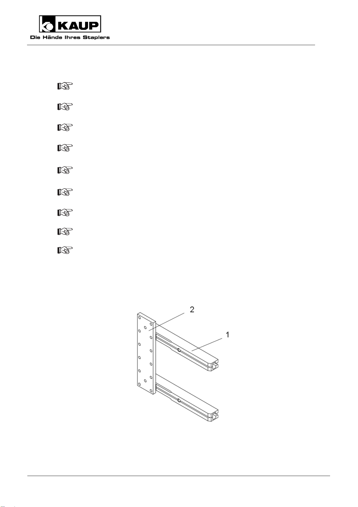
3.1 Slides........................................................................................................................................ 6
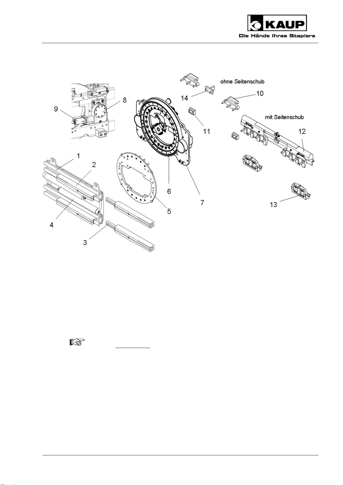
3.2 Rotating Clamp with mounting................................................................................................. 7
3.3 Efficient equipment settings on electric vehicles ..................................................................... 7
3.4 Proper use of the equipment.................................................................................................... 7
3.5 Improper use............................................................................................................................ 8
3.6 Hydraulic oil flow required........................................................................................................ 8
4. Installation and checking out ................................................................................................................ 9
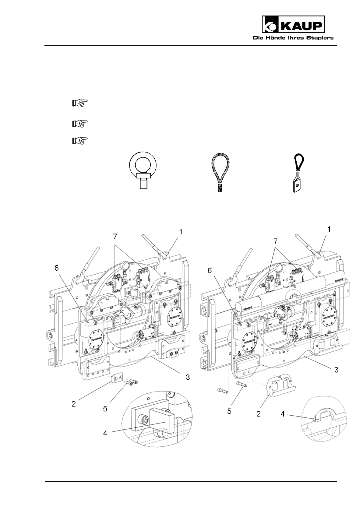
4.1 Installation................................................................................................................................ 9
4.2 Checking out .......................................................................................................................... 10
4.2.1 Bleeding the hydraulic system ................................................................................... 11
4.2.2 Adjustment after putting into service.......................................................................... 11
5. Operation ............................................................................................................................................... 12
5.1 General................................................................................................................................... 12
5.2 Load handling......................................................................................................................... 13
5.3 Driving.................................................................................................................................... 13
5.4 Rotate..................................................................................................................................... 13

Operating Manual
Original Operating Manual
3
6. Maintenance and servicing...................................................................................................................14
6.1 General ...................................................................................................................................14
6.2 Significant modification...........................................................................................................15
6.3 Schedule for routine maintenance and lubricants ..................................................................15
6.3.1 Clamp..........................................................................................................................16
6.3.2 Clamp and flange........................................................................................................17
6.3.3 Rotator and flange ......................................................................................................18
6.3.4 Rotator mounting without sideshift .............................................................................19
6.3.5 Rotator mounting with sideshift...................................................................................19
6.3.6 Identification plate and caution board.........................................................................21
7. Troubleshooting.....................................................................................................................................22
8. Disposal..................................................................................................................................................25
9. Transport ................................................................................................................................................25
10. Decommissioning and storage ............................................................................................................25
11. Spare parts list (not part of the Operating Manual) ...............................................................................25
12. EC declaration of incorporation of partly completed machinery (Summary) .................................26
Our service department in Aschaffenburg will be happy to answer your technical questions and to provide additional support.
Technical Support:
0049 (0)6021 865 395
0049 (0)6021 865 284
0049 (0)6021 865 352
Orders for spare parts Domestic
0049 (0) 6021 865205
0049 (0) 6021 865251
Orders for spare parts Export
0049 (0) 6021 865344
0049 (0) 6021 865348
Outside of normal business hours the Kaup –Service Hotline is available to you 365 days a year:
0049 (0) 172 6295 297
Monday - Friday: 5 pm to 7 am
Saturday and Sunday: 8 am to 6 pm
Kaup GmbH & Co KG • Braunstr. 17 • D-63741 Aschaffenburg • email: [email protected] •
www.kaup.de

Operating Manual
4
Original Operating Manual
1. Introduction
1.1 Working with this manual
This operating manual contains important information on how to operate the attachment properly,
safely and efficiently.
The operating manual shall be read, understood and applied by all personnel working on or with the
equipment, for example:
Installation and operating the equipment
Inspection, maintenance and repair
Transport and disposal
The manual must be kept available for ready reference at the equipment’s place of use.
The illustrations in this operating manual may deviate from the actual version
of the equipment.
1.2 Warning notes and symbols
The following symbols are used in this operating manual to highlight details of special importance:
Identifies details relating to do’s and don’ts for the purpose of avoiding injury
and property damage.
Specific details relating to the efficient use of the attachment and other advice.
Lists are denoted by a shadowed box.
Steps to be performed by the operator are denoted by a black dot.
(1)
In illustrations, particular elements have numbered pointers. Numbers in brackets in
the text refer to the corresponding elements.
1.3 Copyright
This documentation including all parts is copyrighted. Any use or change outside the narrow limits of
copyright law without permission from KAUP GmbH & Co KG is forbidden and liable to prosecution.
This applies, in particular, to reproduction, translation, microfilming as well as storage and
processing in electronic systems.

Operating Manual
Original Operating Manual
5
1.4 Qualified and authorised personnel
Qualified and authorised personnel are equipped by way of their education and training to perform
the tasks assigned to them in accordance with accepted practice and safety regulations. They are
assigned tasks by the equipment owner.
1.5 Warranty claims based on defects
KAUP shall not be liable for any damage to the equipment resulting from:
Improper use / operation.
Modifications to components.
Inappropriate installation, maintenance, inspection and servicing.
Assignment of unqualified or non-authorised personnel.
Claims raised by third parties.
1.6 Limits of applicable use
KAUP-attachments are intended for use under the following climatic conditions:
Average ambient temperature for continuous operation:
+25°C
Allowable maximum ambient temperature, short term (up to 1h):
+40°C
Allowable minimum ambient temperature for attachments intended for
indoor use:
+5°C
Allowable minimum ambient temperature for attachments intended for
outdoor use:
-20°C
Standard models of KAUP-attachments are NOT suitable for:
Use in cold storage facilities.
Use in explosive environments.
Use in conjunction with hydraulic systems involving biological oils.
Use in rough environmental conditions (e.g. seawater)
The transport of acidic liquids.

Operating Manual
6
Original Operating Manual
2. Safety aspects
As the user, extend the safety instructions with generally applicable, legal and other
measures that ensure a safe and environmentally friendly operation of the
attachment.
Pay close attention to all safety- and danger-related signs on the attachment and in
this operating manual. Failure to observe these can result in severe injury or even
death.
Pay close attention to the operating manual provided by the manufacturer of the fork
lift truck.
Keep a safe distance away from moving, reciprocating or rotating parts of the
attachment to avoid danger of crushing, pinching or entanglement.
Notify the responsible department/person immediately of changes and faults in
operation of the attachment that affect safety.
The attachment shall be shut down.
Use aids to vision (e.g. mirrors, camera, etc.) where goods being transported obstruct
vision.
Only allow work on the attachment to be carried out by qualified and authorised
persons. Adhere to the legal minimum age in the country of operation!
The attachment should only be used for the purpose intended.
Never work on or with attachments while under the influence of drugs, alcohol or
medicines which affect reaction time.
3. Design
3.1 Slides
Model T 450A / T 490A consists of guide profiles (1) and a plate welded on (2). Arms are bolted onto
these welded plates (2) by the operator.

Operating Manual
Original Operating Manual
7
3.2 Rotating Clamp with mounting
A Rotating Clamp consists of a clamp body (1) on which conduits (2) are mounted. Cylinders (4)
move the conduits (2), which are equipped with sliders (3). The clamp body (1) is mounted on a
flange (5) that is bolted to a rotary joint (6). There is a drive (8) on the base plate (7) consisting of a
bevel gear, gear box and hydraulic motor (9) attached. This combination is attached to the fork
carriage of the lift truck with upper (10) and lower brackets (11). A central catch (14) bolted to the
base plate (7) prevents the rotator being deflected off the fork carriage of the lift truck. The optional
side shift (12) is equipped with support rollers (13) and is bolted or welded onto the base plate (7).
3.3 Efficient equipment settings on electric vehicles
Please use our reference values for setting the lift trucks and attachments. These are
found at www.kaup.de in the Services -> Product Support section.
3.4 Proper use of the equipment
Arms/fork arms can be bolted onto models T450A and T490A by the operator. These can either be
simply pushed or loads can be clamped with them.
The operator is required to define proper and improper use for its bolted on arms/fork arms in
combination with the machine supplied.

Operating Manual
8
Original Operating Manual
Proper use of the machine and/or equipment includes the following:
Observance of the operating manual at all times.
Observance of the technical data on the identification plate on the attachment.
Adherence to the specified inspection and maintenance instructions.
3.5 Improper use
Exceeding the allowable load capacity and load centre.
Dragging or pushing loads with the attachment
Transporting persons with the load or load handling devices
Mounting auxiliary equipment on the attachment such that the original mode of usage
is changed, (e.g. fork extensions) must be authorised by the manufacturer.
3.6 Hydraulic oil flow required
When the hydraulic oil flow is insufficient, the speed of rotation of the rotary units at
the attachments will be reduced.
When the hydraulic oil flow is too high, the hydraulic oil temperature will raise which
will reduce efficiency and increase wear.
Please refer to the following Specifications:
ISO Class,
Model family,
Oil flow.
2328
l/min
2
1T - 2,5T
20
± 5
3
2,5T - 4,8T
40
± 10
4
4,5T - 5T
50
± 20
6T - 8T
60
± 15

Operating Manual
Original Operating Manual
9
4. Installation and checking out
4.1 Installation
Installation and commissioning should be performed by qualified and authorised
personnel only.
Pay attention to a sufficient load-carrying capacity of the lifting means.
The following are examples of preferred lifting means:
Capacity
250 kg/M16
1200 kg/M16
2000 kg/M16
Part-no.
9710160008
0360010201
0360010301

Operating Manual
10
Original Operating Manual
Replace the plug screw (6) in the gear box with the vent screw supplied.
Ensure that no oil leaks out of the gear transmission.
Hoist the attachment at the positions indicated (1).
Demount the lower hooks (2).
Mount the attachment on the fork carriage of the lift truck (3).
Check that the attachment is correctly seated in the centre lock (4).
Mount the lower hooks (2), tightening the screws (5) with a torque of 190 Nm.
Use pipes or hoses to connect the hydraulic ports (7) to the hydraulic ports of the lift
truck.
Trucks equipped with attachments which hold the load by power (e.g. paper clamp)
shall feature control(s) with a secondary action to prevent unintentional release of the
load. Also take note in this respect of the operating instruction of the lift truck.
Before initial operation, check the functions and the identification of the attachment
with the movement directions of the operating elements (operating lever, joystick,
etc.).
Mount the residual carrying capacity notice and identification of the operating
elements (if not already present) of the combination of lift truck/attached equipment
on the lift truck.
4.2 Checking out
KAUP-attachments are delivered pre-lubricated. If the attachment has been in storage
for a longer period, we recommend that it be lubricated again before being placed in
service. See 6. Maintenance and onwards.
Failure of the safety devices (e.g. the pressure relief valve and the non-return
valve) and incorrect connection of the controls to the actuators can cause
malfunctioning of the attachment and damage to it.
After mounting and before initial operation, check the functions and the
identification of the attached equipment with the movement directions of the
operating elements (operating lever, joystick, etc.).

Operating Manual
Original Operating Manual
11
4.2.1 Bleeding the hydraulic system
Start the lift truck.
Move the sideshifter repeatedly in both directions to maximum extent.
Rotate the rotator left and right several times.
Repeatedly cycle the clamp / fork positioner from the fully open to the fully closed
position.
Inspect the hydraulic connections for leakage.
4.2.2 Adjustment after putting into service
The hydraulic system is under pressure. During work on hydraulic components
oil spurting out can cause injuries. Unload the system in accordance with the
operating instructions of the lift truck manufacturer. In the case of injuries
caused by high pressure oil, inform the works physician and seek out a
specialist immediately.
Synchronising the arms
The synchronization of arms is adjusted ex-factory. This can alter for different friction
conditions (wear), temperatures and volumes conveyed. Perform a readjustment. The
recommended working temperature of the hydraulic fluid is approx. 35 °C.
The synchronization is adjustable by means of two throttles on the bottom of the cylinders.
Setting the clamping pressure with a pressure limiting valve
Attachments are adjusted ex-factory to a pressure of 160 bar.

Operating Manual
12
Original Operating Manual
A change in pressure is necessary only, if the load
slips or
is damaged.
Make the settings in the numerical sequence and in the direction of the arrows.
The pressure indication on the manometer gauge drops after clamping.
This is not a malfunction of the attachment, being caused by the installation of a
transmission
5. Operation
(related to the bolted on fork arms. With other arm designs, these operating instructions must be
extended with instructions from the operator.)
5.1 General
At least once per working shift, the machine and equipment must be
inspected for visible damage and defects.
Repeat faults to your superior and have them rectified without delay.
Be aware of persons present in the area where you are working or driving
and ensure that they are not endangered.
Do not transport any load exceeding that specified on the residual load
plate for the particular combination of lift truck and attachment.
Note the load-bearing capacity of the attachment as stated on the rating
plate. This figure always represents the load carried by two or more fork
arms.
The nominal capacity of the forks must exceed the load.
Ensure that fork arms and arms that clamp a load are closer together at the
tips than at the back. As a result you need a larger clearance for moving in.

Operating Manual
Original Operating Manual
13
5.2 Load handling
Set the forks as wide apart as possible for the load to be carried.
Position the mast vertically and take up the load parallel to the floor.
Always transport pallets, boxes and containers using both forks.
Drive the attachment up to the load to maximum extent.
Raise the load about 300 mm and tilt the mast backwards.
Centre the load to the middle of the lift truck during take-up and transport.
5.3 Driving
Ensure that pallets, boxes, containers and packaging are in good condition.
Do not drive with the mast tilted forward.
Take care when driving that neither the attachment nor the load comes into contact
with the ground.
Ensure that multiple items stacked on top of one another are securely fastened.
5.4 Rotate
Rotation can cause damage to the load and the attachment.
Ensure sufficient distance of the load to the floor, the ceiling, to shelves, etc.
If higher torque than specified is generated by the load, the rotation device
rotates uncontrolled or not at all.
This can lead to damage to the load and the attachment.
Note the torque given on the type plate of the attachment.
The torque given on the type plate refers to the pressure difference of 125 bar at the
hydraulic motor.
Only rotate loads parallel to the floor (set lifting frame vertically).
Do not rotate loads if there are people in the working area.
Rotate raised loads slowly.
Fast rotating can influence the stability of the lift truck.

Operating Manual
14
Original Operating Manual
Ensure that carrying equipment, e.g pallets, crates, containers are not tipped off
during rotating.
6. Maintenance and servicing
6.1 General
Regular maintenance is essential to ensure reliable operation and long service life of the KAUP
attachment.
Ensure that maintenance and servicing are performed by qualified and authorised
personnel only.
Lubrication and cleaning work on the attachment may also be performed by the lift truck
operator.
Perform maintenance and servicing work only when the attachment is parked securely
on a stable, level foundation. For installing and removing, it is recommended to use a
pallet to take the attachment. The attachment can thus be securely placed and
transported.
Pay attention to a sufficient load-carrying capacity of the lifting means.
Replace missing or defective warning signs on the attachment.
Do not use third party spare parts. Through poor quality or incorrect matching
they can result in a risk of accident. The EC Declaration of Conformity by the
manufacturer becomes invalid and you assume full responsibility in the case of
accident.
Use only original spare parts from the manufacturer.
The hydraulic system is under pressure. During work on hydraulic components
oil spurting out can cause injuries. Unload the system in accordance with the
operating instructions of the lift truck manufacturer. In the case of injuries caused
by high pressure oil, inform the works physician and seek out a specialist
immediately.
Screw connections can loosen due to vibration of the attachment. During routine
maintenance check that screw connections are correctly torqued and replace
screws which are visibly damaged.

Operating Manual
Original Operating Manual
15
Note the following tightening torques which are valid for screws with connecting surfaces according
to ISO 4762, ISO 4014, ISO 4032 etc.:
Screw/bolt rating
8.8
10.9
12.9
M6 thread
9,3Nm
14Nm
16Nm
M8 thread
23Nm
33Nm
39Nm
M10 thread
45Nm
66Nm
77Nm
Μ12 thread
77Nm
115Nm
135Nm
Μ16 thread
190Nm
280Nm
330Nm
Μ20 thread
385Nm
550Nm
640Nm
During any disassembly operations, be sure that parts to be disassembled can easily be
removed. For removing parts, use the clearance between bolts and the parts to be
removed.
Our service videos available at www.kaup.de in the Online Services section may be
used for assistance as necessary.
Failure of the safety devices (e.g. the pressure relief valve and the non-return
valve) and incorrect connection of the controls to the actuators can cause
malfunctioning of the attachment and damage to it.
After mounting and before initial operation, check the functions and the
identification of the attached equipment with the movement directions of the
operating elements (operating lever, joystick, etc.).
6.2 Significant modification
Significant modifications are, for example, those which affect the stability, performance, speed and
strength of components.
Modifications to the attachment may only be made with prior approval by the manufacturer.
6.3 Schedule for routine maintenance and lubricants
Lubricants approved and recommended by KAUP
Greases
Note
Lithium soap grease
NLGI Class 2
e.g. Avialith 2
Designation DIN51825:
K 2 K-30
Complex soap grease
NLGI Class 2
e.g. Turmogrease Gel M 5
Foundry quality
Teflon spray
e.g. Wieds or Rivolta
Only for plastic sections

Operating Manual
16
Original Operating Manual
Hydraulic oil
gear box 80
0520990036
e.g. Avia Gear RSX 680, DIN 51517
Filling capacity
0,5.l
0520990080
0520990019
gear box 125
0520990037
e.g. Avia Gear RSX 680, DIN 51517
Filling capacity
2,0 l
0520990075
e.g. Klüber Syntheso D 460 EP
0520990085
e.g. Avia Gear RSX 680, DIN 51517
gear box 200
0520990070
e.g. Klüber Syntheso D 460 EP
Filling capacity
9,5 l
0520990071
The specified maintenance schedules can change as a result of the operating conditions
such as extreme cold, heat and dust or poor ground conditions and this must be taken
into account by the owner.
With other loads, such as fork arms with a length of over 2,400 mm or raised load
centres, amended/shorter maintenance intervals should be agreed by the user with the
manufacturer.
6.3.1 Clamp

Operating Manual
Original Operating Manual
17
6.3.2 Clamp and flange
Daily
Check all lines, hoses and connections for leakage and damage.
After 50h / every 500h thereafter
Check screws:
(10) on the clamp body (7, 9) / flange (11).
Replace loose or damaged screws. Torque the screws as specified in Chapter 6.1
General.
Weekly
Grease:
Sliding pieces (2) by way of the greasing nipples (1).
The supporting rollers in the standard version are maintenance-free.
Every 200h
Check wear on:
Sliding pieces (2).

Operating Manual
18
Original Operating Manual
As necessary
Replace worn sliding pieces (2) by removing nut (5) from each cylinder (6). Pull the
arms to the side to remove (see Chapter 3.1). Remove the greasing nipple (1) and the
screw/s (3, 3a). Replace the sliding pieces (2). When installing the new sliders, make
sure that the axial stops (4) are correctly seated. Refit the screw (3, 3a) and the
greasing nipple (1). Push the arms into clamp body and reinstall nuts (5) of cylinders
(6).
After installing or removing a cylinder (6), always check the clearance between the
cylinder mount and nut of the cylinder (8). Cylinders are installed with axial clearance
of 1.5 to 2 mm.
6.3.3 Rotator and flange

Operating Manual
Original Operating Manual
19
6.3.4 Rotator mounting without sideshift
6.3.5 Rotator mounting with sideshift

Operating Manual
20
Original Operating Manual
Daily
Check all lines, hoses and connections for leakage and damage.
After 50h / every 500h thereafter
Check scews:
(1) on the slewing ring (3) / flange (2).
(4) on the slewing ring (3) / base plate (5).
(6, 7, 9) on the gear (8).
(10) on the oil motor (11).
(15), nut (16) on the spacer (18) and lower hooks (17).
(19) on the spacer (21) and lower hooks (20).
(22) on the central catch (14).
(26), nut (23) on the sideshifter housing (27).
(28) on the lower hooks (29).
Replace loose or damaged screws. Torque the screws as specified in Chapter 6.1
General.
Weekly
Grease:
Sliding pieces (25) by way of the greasing nipples (24).
Supporting rollers (30) on the lower hooks (29) as necessary.
Every 200h
Check wear on:
Sliding pieces (25).
Supporting rollers (30).
Prevent entry of dirt, water or moisture into the slewing ring.
Grease:
Slewing ring (3) by way of the greasing nipples (12).
Gearing of the rotary joint (3) by way of the greasing nipples (13).
Every 500h
Check the oil level of the gear box (8).
This manual suits for next models
5
Table of contents
Other KAUP Valve Positioner manuals
Popular Valve Positioner manuals by other brands

rotork
rotork YT-3300 Series product manual

Leuze electronic
Leuze electronic BPS 8 Original operating instructions

Trimteck
Trimteck Optimux HPP5500 Series product manual

Vector
Vector TCY-MZ manual

Samson
Samson 3785 series Mounting and operating instructions

Flowserve
Flowserve ARGUS MW 8 Installation and operating instructions