manuals.online logo
Brands
  1. Home
  2. •
  3. Brands
  4. •
  5. Kaye
  6. •
  7. Mobility Aid
  8. •
  9. Kaye B Series User manual

Kaye B Series User manual

“B” SERIES KAYE POSTURE CONTROL WALKERS
(effective 2/02/04)
These are the user instructions for the
“B” Series Kaye Posture Control Walkers. All
persons who set-up, adjust, or use the walker
should first read these entire instructions.
Walkers with seats have a second set of
instructions that detail the seat usage.
Please store the instructions for future
reference.
USE
The Kaye Posture Control Walker is
designed as a reverse or posterior walker,
where the user faces away from the rear bars
and towards the open end of the walker. These
walkers are designed to facilitate postural
alignment, balance, and components of gait
through the following means (as compared to
traditional, forward walkers):
1. The support behind the user encourages a
more upright posture.
2. The handgrips beside the user encourage
improved upper extremity position.
3. The centering of the user within the
walker and over his own feet encourages the
development of balance.
4. The rear horizontal bars encourage the
user to step forward as he moves the walker
forward.
5. Pulling the walker helps eliminate the
abnormal two-footed stance when a user must
stop and move the walker further to their
front.
FRAME DESIGNS
The W1/2B, W1B, W2B, W3B, and W4B
series walkers are designed to be used as
regular walking aids.
The R2B, R3B, and R4B series walkers
are designed with additional interior room for
users who wear leg braces.
WHEEL DESIGNS
The two-wheeled design provides extra
drag for users who cannot yet manage a walker
that rolls forward as they shift their weight
forward.
The four-wheeled designs help improve
cadence, velocity, energy use, and step and
stride length. All four-wheeled walkers have
locking rear wheels to prevent them from
rolling backwards.
The swivel front wheels allow the user
to turn without having to lift and reposition
the walker.
WALKER IDENTIFICATION, AND SIZE AND WEIGHT
LIMITS
The model number is on the warning
label and the yellow/orange leg label. (“H” or
“-seat” denotes a fold-down seat; “R” denotes
four wheels; “S” denotes four wheels with
swivel front wheels; “X” denotes silent rear
wheels.)
The following chart lists height and
weight limits for each walker as follows:
A = Height adjustment, in inches, from the
floor to top of the grip. This should match
the height from the floor to the middle of the
user’s buttocks.
B = Height adjustment, in cms.
C = Maximum weight limit, in lbs.
D = Maximum weight limit, in kgs.
MODELS A
(ins.) B
(cms.) C
(lbs.) D
(kgs.)
W1/2B,
W1/2BH 14.5 - 20.0 37-51 60 27
W1/2BR,S,X
W1/2BHR,S,X 14.5 - 18.0 37-46 60 27
W1B, R, S, X
W1BH,R,S,X 16.5 - 22.0 42-56 60 27
W2B, R, S, X
R2B, R, S, X 19.0 - 25.0 48-64 85 39
W3B, R, S, X
R3B, R, S, X 23.0 - 30.5 58-77 130 60
W4B, R, S, X
R4B, R, S, X 28.0 - 36.0 71-91 180 82
FOLDING AND UNFOLDING
To unfold the walker, pull the hand
grips away from the rest of the frame, and the
walker should begin to unfold. Continue to
unfold the frame until the latch pushpins
extend and lock as shown in Figure A.
To fold the walker, face it from the
open end, depress the latch push-pins, tilt
the walker so that it rests on its rear legs
only, and push the front legs towards the rear
legs.
“B” Walkers, 2/02/04, page 2
ASSEMBLY
Some walkers are shipped with the legs
removed. Install the legs as follows:
1. The front legs have wheels that rotate in
both directions. Install the front leg with
the orange sticker into the front, left side
of the frame. Install the other front leg into
the front, right side of the frame.
2. Install the rear legs with tips so that
the bend points the tip towards the front of
the walker.
3. The rear legs with wheels have wheels that
rotate in only one direction. Install the rear
leg with the orange sticker into the rear,
left side of the frame. Install the other rear
leg into the rear, right side of the frame.
HEIGHT ADJUSTMENT
Adjust the height of the walker so that
the top, rear bar is aligned with the middle
of the user's buttocks. To do this, press the
pushpin on each leg and slide the leg up or
down as needed.
After installing or adjusting the legs,
always check the following:
1. All four extensions must be adjusted to
the same height.
2. The pushpins must protrude fully from the
adjustment holes.
3. The wheels should face towards the outside
of the walker.
4. If you have rear legs with tips, the bend
should point the tip towards the front of the
walker.
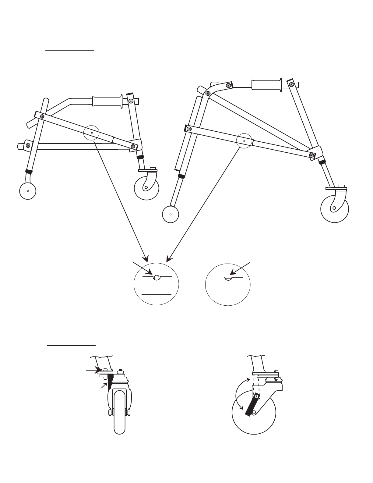
5. If you have swivel front wheels, the
plates should be parallel with the ground and
protrude from the walker as shown in Figure B.
6. If you have rear wheels, the locking
mechanism on the rear wheels should prevent
the walker from rolling backwards.
UNLOCKING AND LOCKING THE SWIVEL WHEELS
To unlock the front wheels so that they
swivel, rotate each swivel latch around and
down, as shown in Figure B, until it rests
against the bolt that serves as an axle for
the wheel.
To prevent the wheels from swiveling,
first point the wheel straight ahead as shown
in Figure B. Then rotate each latch around and
up until it is seated fully into the slot
located in the plate above the wheel.
ADJUSTING ALIGNMENT, SWIVEL WHEELS
Adjust the alignment of the swivel
wheels as follows:
1. Ensure that the swivel caster is locked as
shown in Figure B.
2. Use 1/2” wrenches to loosen bolt “X”.
3. Point the caster assembly in the desired
direction.
4. Securely tighten the bolt.
ADJUSTING NON-SWIVEL WHEELS, FRONT AND REAR
Use 9/16” wrenches to adjust the
optional, silent rear wheels. Use 3/4”
wrenches to adjust the front, “all-terrain”
wheels. Use 1/2” wrenches to adjust all other
wheels. A flat-head screwdriver may also be
needed.
Adjust the alignment of the non-swivel
wheels, front or rear, as follows:
1. If a bolt head, which is located on the
outside of the wheel, is concealed by a
plastic cover, remove that cover. To do this,
insert the tip of a flat-head screwdriver just
under the edge of the plastic cover and gently
pry the cover off of the metal flange. The
bolt head should then be visible.
2. Secure the bolt head on the outside of the
wheel so that it does not turn.
3. Loosen the nut that is located on the
opposite side of the leg as is the wheel.
4. If you have silent rear wheels, you may
also need to loosen the nut between the leg
and the wheel. To do this, move that nut away
from the leg. (It may be necessary to rotate
the bolt head in order to loosen this nut.).
5. Adjust the alignment as desired.
6. Move the wheel up or down to ensure the
walker is level.
7. Secure the bolt head that is on the
outside of the wheel so that it does not turn.
8. Identify the nut that is on the opposite
side of the leg as is the wheel. Securely
tighten that nut into the tube.
9. If you have silent rear wheels, identify
the nut that is between the wheel and the
tube. Securely tighten that nut into the tube.
OPTIONAL REAR LEGS WITH SILENT, ONE-WAY
BEARINGS
Rear leg extensions with silent, one-
way bearings are available as an option for
these walkers. Model RR1/2B fits W1/2B and
W1/2BH frames; RR1B fits W1B and W1BH frames;
RR2B fits W2B and R2B frames; RR3B fits W3B
and R3B frames; and RR4B fits W4B and R4B
frames.
Install these legs as described under
ASSEMBLY, step 3.
Adjust these legs as described under
ADJUSTING NON-SWIVEL WHEELS, FRONT AND REAR.
However, after adjustment, both nuts must be
tightened very securely against the tube, or
the following difficulties may occur:
1. When rearward pressure is applied, the
one-way bearing may turn the bolt. When
this occurs, the wheel can become
misaligned and/or become loose on the
leg. To correct this, adjust the wheel as
described in the previous section and
very securely tighten both nuts into the
tube.
2. If the bolt turns, as described above, it
may permit the nut between the wheel and
the leg to turn. The nut may then bind
against the wheel and prevent the wheel
from turning. To correct this:
a) Identify the nut that is between the
wheel and the leg.
b) Use a wrench to move that nut away
from the wheel, just until the wheel
can rotate forward without binding.
c) Adjust the wheel as described in the
previous section and very securely
tighten both nuts into the tube.
ANTERIOR OR FORWARD WALKERS
The leg extensions can be rearranged to
make the following models forward walkers:
W2B, R2B, W2BR, R2BR, W3B, R3B, W3BR, R3BR,
W4B, R4B, W4BR, and R4BR.
The W1/2B, W1/2BH, W1/2BR, W1/2BHR,
W1B, W1BH, W1BR, and W1BHR walkers can be
special-ordered as forward walkers.
“ALL-TERRAIN” WHEELS
Optional leg extensions with large or
“all-terrain” wheels are available for these
walkers. The front legs have 9” dia., non-
swivel wheels. The rear legs have 5” dia.
wheels with external ratchet mechanisms.
Model W1BAC fits W1B and W1BH frames;
W2BAC fits W2B and R2B frames; W3BAC fits
W3B and R3B frames; and W4BAC fits W4B and
R4B frames.
OTHER ACCESSORIES
Walkers with fold-down seats are
available. Contact Kaye Products, Inc. for
more information about seated walkers. The
seats will not retrofit existing walkers.
Forearm supports, pelvic stabilizer
side pads, and extensor assist center pads
are available for these walkers.
Guide handles are available for the
W1/2B, W1/2BH, W1B, W1BH, W2B, and W3B
series walkers.
The accessories include their own user
instructions.
“B” Walkers, 2/02/04, page 3
Please call Kaye Products, Inc. or
consult their catalog for more details.
MAINTENANCE AND CARE
Inspect the walker regularly. Tighten
the nuts and bolts as necessary.
If a product needs service or spare
parts, contact Kaye Products, Inc. or the
dealer from whom you purchased the item.
If a problem is discovered that may
impact the product’s function, immediately
cease use and contact Kaye Products, Inc.
The wheels and crutch tips will wear
and should be replaced as needed.
The ratchet or brake mechanisms on the
rear wheels will wear and should be replaced,
as needed, in order to maintain the rear-
braking feature. Dirt, trash, or ice build-up
on the ratchet mechanisms may prevent them
from functioning.
If your walker has the rear wheels with
silent, one-way bearings, care should be taken
to avoid exposing these bearings to salt or
salt water.
Use water and, if needed, soap to clean
the walker.
Avoid any undue stress to the walker
while using, storing, or transporting it.
LIMITED WARRANTY
If an item proves defective within two
years of the original purchase, we will
provide you with replacement parts in order to
correct that defect. Wear and tear, and the
items listed under MAINTENANCE AND CARE are
not covered by the warranty.
Kaye Products, Inc. makes no other
warranty, expressed or implied, and does not
warrant the product as being fit for a
particular purpose. The purchaser, owner, and
user assume all risk of personal and property
injury due to the use of the equipment.
CAUTIONS
1. Not for elderly.
2. Each time you unfold or adjust the walker,
ensure that pushpins fully extend from their
corresponding holes.
3. Do not use with broken or missing parts.
4. Do not use on stairs, steep slopes, or
steep ramps.
5. Do not exceed the size and weight limits.
6. Do not alter the product or use it in any
way other than described herein.
7. Never leave a child unattended.
8. Always use qualified supervision.
QUESTIONS?
If you have any questions, please
contact Kaye Products, Inc.
Our authorized representative for the
European Medical Device Directives is Advena,
Ltd., PO Box 30, Leominster, Herefordshire,
RH12 2BT, UK.
FRONT
OF
WALKERS
Correct
snap button
fully extended
Incorrect
snap button
not extended
Bolt X
INSIDE OUTSIDE
Latch up
& locked
Locked
Unlocked
BACK FRONT
Figure B
Figure A
W 1/2 & 1 BS Models W 2, 3, & 4 BS Models

This manual suits for next models

40

Other Kaye Mobility Aid manuals

Kaye 5C Series User manual

Kaye

Kaye 5C Series User manual

Kaye SW7 Series User manual

Kaye

Kaye SW7 Series User manual

Popular Mobility Aid manuals by other brands

medi protect.ROM manual

medi

medi protect.ROM manual

Medinox mx mobility MX79304 Instructions for use

Medinox

Medinox mx mobility MX79304 Instructions for use

Guldmann GH Service guide

Guldmann

Guldmann GH Service guide

LiftSeat Independence Owner's operator and maintenance manual

LiftSeat

LiftSeat Independence Owner's operator and maintenance manual

Costway JH10010 Instruction booklet

Costway

Costway JH10010 Instruction booklet

Otto Bock Kenevo manual

Otto Bock

Otto Bock Kenevo manual

HT Systems Kera sit2sit quick guide

HT Systems

HT Systems Kera sit2sit quick guide

Invacare 65109 Assembly, installation and operating instructions

Invacare

Invacare 65109 Assembly, installation and operating instructions

Quickie P-11 instruction manual

Quickie

Quickie P-11 instruction manual

Mopedia IM100 instruction manual

Mopedia

Mopedia IM100 instruction manual

Westfalia 80 13 29 instruction manual

Westfalia

Westfalia 80 13 29 instruction manual

AMF-BRUNS EURO RAMP operating instructions

AMF-BRUNS

AMF-BRUNS EURO RAMP operating instructions

Peak Tri-Wheeled Walker user manual

Peak

Peak Tri-Wheeled Walker user manual

Pressalit Care R84353 Mounting instruction

Pressalit Care

Pressalit Care R84353 Mounting instruction

Gima FS927L user manual

Gima

Gima FS927L user manual

Otto Bock Veldink4kids Kiddo Classic Instructions for use

Otto Bock

Otto Bock Veldink4kids Kiddo Classic Instructions for use

Eurovema Euroflex Miniflex Classic manual

Eurovema

Eurovema Euroflex Miniflex Classic manual

Decon wheel MED3197 Assembly instructions

Decon wheel

Decon wheel MED3197 Assembly instructions

manuals.online logo
manuals.online logoBrands
  • About & Mission
  • Contact us
  • Privacy Policy
  • Terms and Conditions

Copyright 2025 Manuals.Online. All Rights Reserved.