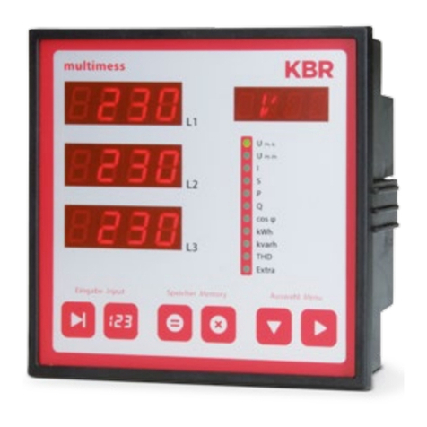
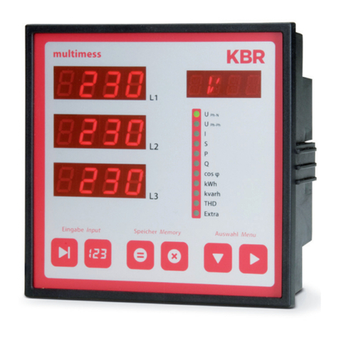
KBR multimess F144-2-LED-ESMS 4 Series User manual

22067_EDEBDA0239-3617-3_EN
User manual
Technical parameters
Your partner for
network analysis
Three-phase
network measuring device
F144-2-LED-ESMS...-4
multimess
System IEnglish

© KBR Kompensationsanlagenbau GmbH
Misprints, printing errors
and technical changes reserved
2
KBR multimess F144-2-LED-ESMS...-4 Table of contents
1 Device memory, battery-buered 8
2 Denition of terms........................... 10
3 Field of application /
range of functions............................ 11
4 Connecting the multimess
F144-2-LED-ESMS-...-4 .................... 13
4.1 Installation and assembly ............. 13
4.2 Installation.......................................... 13
4.3 Connection diagram....................... 17
4.4 Terminal assignment....................... 18
5 Control and display panel............. 20
5.1 Description of sensor buttons
and displays ....................................... 21
6 Operation............................................ 22
6.1 Menu structure of the multimess
F144-2-LED-ESMS-...-4 .................... 22
6.2 Navigation and device displays .. 23
7 Setting operating parameters..... 24
7.1 General programming scheme... 24
7.2 U Ph-Ph - Measuring reference
voltage / rated mains voltage...... 25
7.3 I - Current transformer ratio ......... 26
8 Display functions.............................. 27
8.1 UPh-N - Voltage phase to neutral
conductor, frequency ..................... 27
8.2 UPh-Ph - Voltage phase to phase,
rotary eld display ........................... 28
8.3 I /IN - Current / neutral conductor
current, instantaneous and
average value switch-over............ 29
8.4 S - Apparent power / total
apparent power ................................ 30
8.5 P - Active power / total
active power ...................................... 31
8.6 Q - Reactive power / total
reactive power................................... 32
8.7 Cos φ - Fundamental power
factor, PF, total PF............................. 33
7.8 kWh - Active energy HT/LT
consumption and recovery,
maximum cumulated cycle
active power ...................................... 34
8.9 kvarh - Reactive energy meter
HT/LT consumption and recovery,
maximum cumulated cycle
reactive power................................... 36
8.10 Harmon. - distortion factor and
partial harmonic content of the
voltage and current network
harmonics ........................................... 38
8.11 Extra ...................................................... 39
8.12 Maximum / Minimum
extreme values display................... 43
8.13 Displaying limits ............................... 46
9 Programming..................................... 49
9.1 Period time current
average value .................................... 49
9.2 Tari switching method................. 50
9.3 Measurement period
synchronization ................................ 51
9.4 Programming limits......................... 52
9.5 Setting time and date..................... 54
9.6 Setting the bus address ................. 55

Rev. 3.00 3
22067_EDEBDA0239-3617-3_EN
KBR multimess F144-2-LED-ESMS...-4Table of contents
9.7 Setting the bus protocol................ 56
9.8 Setting the Modbus bus
address and baud rate.................... 57
9.9 Setting the relay on-delay
and o-delay...................................... 58
9.10 Activating daylight saving time
and setting the relay o-delay .... 60
9.11 Language settings ........................... 61
9.12 Password ............................................. 62
9.13 Conguring the pulse output...... 63
9.14 Damping coecient ....................... 65
9.15 Default settings................................. 66
9.16 Zero point creator............................ 67
9.17 Analog outputs................................. 68
10 Reset and delete function ............ 72
10.1 Reset ..................................................... 72
10.2 Delete energy meter....................... 72
10.2.1 Delete energy meter manually ... 72
10.2.2 Delete all energy meters ............... 72
10.3 Deleting extreme values ............... 72
10.3.1 Deleting individual
extreme values.................................. 72
10.3.2 Deleting all extreme values.......... 73
10.4 Deleting limit settings.................... 73
10.4.1 Deleting individual
limit settings ...................................... 73
10.4.2 Deleting all limit settings .............. 73
11 Memory functions ........................... 74
11.1 Device settings.................................. 74
11.2 Basic device parameters................ 74
11.3 Long-term memory......................... 75
11.4 Load prole memory ...................... 75
11.5 Annual energy memory................. 75
11.6 Event memory................................... 76
11.7 Measurement period
synchronization ................................ 76
11.8 Synchronization only by
internal clock ..................................... 76
11.9 Synchronization by the energy
supplier’s synchronous pulse....... 77
11.10 Synchronization by KBR eBus ...... 77
11.11 Synchronization at tari change 78
12 Technical data.................................... 79
12.1 Measuring and display values ..... 79
12.2 Measurement accuracy.................. 80
12.3 Measuring principle ........................ 81
12.4 Device memory................................. 81
12.5 Power supply ..................................... 81
12.6 Hardware inputs and outputs ..... 82
12.6.1 Inputs.................................................... 82
12.6.2 Outputs................................................ 82
12.7 Electrical connection ...................... 83
12.8 Mechanical data ............................... 84
12.9 Ambient conditions, electrical
safety and standards....................... 85
12.10 Default settings after reset ........... 86
13 Serial interface .................................. 87
13.1 RS 485 bus operation...................... 87
14 Overvoltage and lightning
protection ........................................... 87
15 Troubleshooting............................... 88
16 Appendix............................................. 90
16.1 Added functionality: Probus...... 90
16.2 Setting the bus protocol................ 90
Rev. 3.00
22067_EDEBDA0239-3617-3_EN
4
KBR multimess F144-2-LED-ESMS...-4 Introduction
Dear customer
Thank you for choosing a KBR product.
To familiarize yourself with operation and conguration of the device, we recommend
that you read this manual carefully. This will enable you to make use of the entire range of
functions that this high-quality product oers.
The individual chapters serve to explain the technical details of the device and show how
to properly install and start up the device to prevent damage.
This user manual is included in the scope of delivery of the device and must be accessible
to the user at all times (e.g. in the switchgear cabinet). Even if the device is resold to third
parties, the manual remains an inherent part of the device.
Although the utmost care has been taken in putting together this user manual, errors
may still occur. We would be very grateful if you could notify us of any errors or unclear
descriptions you may notice. The form included in the appendix to this manual can be
used to send us corrections or suggested improvements.
Yours sincerely,
KBR GmbH Schwabach

Rev. 3.00
22067_EDEBDA0239-3617-3_EN
5
KBR multimess F144-2-LED-ESMS...-4Introduction
This manual contains notes that must be observed for your personal safety and
to avoid damage to the equipment. These notes are identied by a warning
sign or information symbol, depending on the degree of hazard they warn
about.
DANGEROUS VOLTAGE
means that death, major injury or substantial property damage may occur if the
appropriate safety measures are not taken.
CAUTION
means that minor injuries or property damage may occur if the appropriate
safety precautions are not taken.
NOTE
is an important piece of information on the product, product handling or the
respective part of the user manual to which special reference is made.
Disclaimer
The contents of this manual have been checked to concur with the described
hardware and software components. However, deviations may occur, meaning
that no guarantee can be made for complete agreement with the documenta-
tion. The specications given in this manual are checked on a regular basis;
necessary corrections will be included in the next revision.
We appreciate your corrections and comments.
Safety notes
In order to prevent operating errors, handling of the device has been kept as
simple as possible. This will enable you to use the device very quickly. Be sure to
carefully read the following safety notes.

Rev. 3.00
22067_EDEBDA0239-3617-3_EN
6
KBR multimess F144-2-LED-ESMS...-4 Introduction
DANGEROUS VOLTAGE
The applicable DIN/VDE regulations must be observed for installation!
Power supply connection, setup and operation of the device may only be
performed by qualied personnel. Qualied personnel as dened in the safety
notes in this user manual are personnel with electrical engineering qualica-
tions, knowledge of the national accident prevention regulations and safety
engineering standards as well as of the installation, commissioning and opera-
tion of the device.
To prevent re and electric shock, do not expose the device to rain or moisture!
Before connecting the device to the power supply, check whether the local
power supply conditions comply with the specications on the device name-
plate.
A faulty connection may result in the destruction of the device!
When connecting the device, ensure that the data given in the connection
chart is complied with (see "Connection diagram") and that the connection
cables are not live. When wiring, always ensure that all wiring material used is
neither damaged nor defective
and that the polarity is correct!
For proper and safe product operation, ensure that the device is transported,
stored, installed assembled, and carefully operated and maintained in accor-
dance with the specications.
A visibly damaged device must generally be considered unt for use and dis-
connected from the power supply. Troubleshooting, repairs and maintenance
work may only be carried out in our facilities or after contacting our service
team.
Opening the device without authorization will render your warranty null and
void. Correct operation can no longer be guaranteed!
Opening the device may expose live parts. Capacitors in the device may still be
charged, even if the device has been disconnected from all sources of electric-
ity. Do not operate open devices under any circumstances!
All input and output cables of systems that are at risk from lightning strikes
must be tted with lightning protection (see chapter "Protective measures" for
recommendations).
Do not connect external sources of electricity to terminals 36-39, 60-63 and
90-92.
Only apply safe-to-touch extra-low voltage in accordance with UL/CSA/IEC
61010-1 to terminals 34 and 35. Maximum values see technical data.

Rev. 3.00
22067_EDEBDA0239-3617-3_EN
7
KBR multimess F144-2-LED-ESMS...-4Introduction
Product liability
You have purchased a high-quality product.
Only components of the highest quality and maximum reliability are used.
Each device is subject to long-term testing before it is delivered.
For details on product liability, please refer to our general terms and conditions
for electronic equipment.
The warranty on device properties applies only if the device has been operated
in accordance with its intended use!
Disposal
Devices that are faulty, obsolete or no longer used, must be properly disposed
of.
If required, we will dispose of the devices for you.
Scope of delivery
Included in the scope of delivery:
Measuring device
CR2032 battery
Connector set
User manual
Mounting material for the housing

Rev. 3.00
22067_EDEBDA0239-3617-3_EN
8
KBR multimess F144-2-LED-ESMS...-4 Device memory
1 Device memory, battery-buered
NOTE
Before the initial start-up of the device, please insert the backup battery rst (as
described in the following), as otherwise any data stored would be lost in the
event of power failure.
CAUTION
Caution: danger of explosion if battery is replaced incorrectly.
Inserting or replacing the backup battery (see image):
1. Disconnect the device from the power supply.
2. Remove the upper housing cover (frame) using a suitable tool (e.g. a small
screwdriver).
3. Remove the front cover.
4. To replace it, remove the empty battery from the clamp pressing slightly
against the contact spring using pliers.
Caution! To avoid a short circuit, the tips of the pliers have to be insulated.
5. Press the new battery lightly against the contact spring and into the clamp-
ing bracket until it clicks into place. Ensure correct polarity!
6. Put the front cover back into place.
7. Put the device frame back into place and push until it clicks into place.
8. Reconnect the device to the power supply.
NOTE
As there is no power supply if the battery is empty or removed, not only the
stored data are lost but also the time is no longer correct. In this case, the time
has to be reset in visual energy with the corresponding command (see section
"Setting time and date" in the user manual).

Rev. 3.00
22067_EDEBDA0239-3617-3_EN
9
KBR multimess F144-2-LED-ESMS...-4Device memory
Contact spring
Front cover
Battery holder
Battery
Device frame

Rev. 3.00
22067_EDEBDA0239-3617-3_EN
10
KBR multimess F144-2-LED-ESMS...-4 Denition of terms
2 Denition of terms
Below, you will nd a brief explanation of the terminology used in this manual.
Root mean square value:
By denition, the square mean value of a periodic or pulsating
quantity is referred to as the RMS value.
The multimess F144-2-LED-ESMS-...-4 only uses the RMS values of
periodic quantities.
Instantaneous root meansquare value:
The value determined by the multimess F144-2-LED-ESMS-... -4 during
its measurement interval.
Measurement interval:
During a measurement interval, the electrical quantity "voltage" or
"current" of a phase is scanned. The resulting sampling points are
available for further calculations. This interval is mainly determined by
the A/D conversion.
Measuring cycle:
The measuring cycle is the time the measuring device needs in order
to measure all the values recorded by the device for all three phases.
Firmware:
The operating system implemented in the microcontroller of the
multimess F144-2-LED-ESMS-...-4.
Load prole memory:
Saves the actual values of the measurement periods with timestamp.
Measurement period maximum:
The measurement period containing the highest (maximum)
value that occurred.
Active/reactive power periods:
Actual active or reactive power during a measurement period
Measurement period:
The period of time used to determine average power values. Typical
intervals: e.g. 15, 30, 60 minutes.

Rev. 3.00
22067_EDEBDA0239-3617-3_EN
11
KBR multimess F144-2-LED-ESMS...-4Field of application / range of functions
3 Field of application / range of functions
The multimess F144-2-LED-ESMS-...-4 is an aordable network measuring
device for switchboard installation that measures all important parameters in
three-phase networks.
The microprocessor of the multimess F144-2-LED-ESMS-...-4 records the mains
voltage and current consumption of the meter point for all three phases via
analog/digital converter inputs and calculates the active, reactive and apparent
power ratio in the three-phase network.
Convenient operation and display
The LED displays L1, L2 and L3 allow you to read the measured values directly
and enter the respective parameters and conguration data. In addition, eleven
LEDs indicate menus and the status. Six sensor buttons facilitate navigation
through the menus.
For 100 to 400V networks
The multimess F144-2-LED-ESMS-...-4 can be used in 3-wire and 4-wire
networks. The device can be used to make measurements directly in 100 V and
400V networks. Higher voltages can only be connected via external voltage
transformers, with the primary and secondary voltage being programmable.
The measuring voltage inputs of the device measure directly, i.e. they are not
galvanically separated by a voltage transformer!
For energy supply networks with an outer conductor to ground potential, suit-
able ballasts with electrical isolation must be used, e.g. voltage transformers or
zero point creators.
x/5A or x/1A freely programmable
The current measurement inputs must always be supplied via current trans-
formers; the transformer ratio is programmable. The primary current value as
well as the secondary current value can be selected.
Determining the neutral conductor current
The neutral conductor current is calculated and displayed.
Harmonic analysis
Harmonic analysis by Fourier transform.
The multimess F144-2-LED-ESMS-...-4 measures the harmonics of the 3rd / 5th
/ 7th / 9th / 11th / 13th / 15th / 17th and 19th voltage network harmonic, cal-
culates their partial harmonic content, the total distortion factor of the voltage
and the distortion reactive current.
Two-tari meter function (HT/LT)
Consumption during high tari and low tari times is recorded separately.
Switching from high to low tari times and vice versa is either carried out by
means of a digital signal to be applied externally, e.g. from the energy supplier,
or via an internal clock. When operated with the KBR Energy Bus, switching can
be done centrally via the ve-busmaster.

Rev. 3.00
22067_EDEBDA0239-3617-3_EN
12
KBR multimess F144-2-LED-ESMS...-4 Field of application / range of functions
Programmable pulse output
Active energy or reactive energy proportional pulses can be output via a pro-
grammable S0 interface output. The pulse output type (proportional to active
or reactive energy) as well as the pulse signicance (number of pulses per kWh
or per kvarh) and the pulse length can be programmed. These pulses can be
processed by, for example, a master system for data acquisition or optimization,
a maximum-demand monitor or a central process control.
Serial interface
In its default conguration, the multimess F144-2-LED-ESMS-...-4 has a serial
interface (RS485) for operation with the KBR Energy Bus.
A variety of information that cannot be shown on the display can be read from
the device via the bus.
This makes it possible to read numerous online measurement values as well as
a wide range of data can from the long-term memory.
Extensive memory functions
In addition to its meter functions, the multimess F144-2-LED-ESMS-...-4 oers
extensive
memory functions:
a load prole memory to record the cumulated active and reactive power
a memory to record the daily energy values for 365 days
and an event memory that records dened actions of the measuring device,
such as power failures, tari switching actions, delete functions and many
more.
These memory functions are exclusively available via the KBR Energy Bus.
Synchronization
To synchronize the load prole memory, a separate digital input was integrated
into the multimess F144-2-LED-ESMS-...-4 where you can, for example, connect
the synchronization signal of the energy supplier’s meter. Synchronization as
well as switching between high tari and low tari can be done centrally via
the KBR Energy Bus or the internal clock.
Analog outputs
Various parameters between 0-20 mA or 4-20mA and between 0-10V or 2-10V
can be output as analog values.
Depending on which quantity should be output, you can assign it for a certain
phase (L1, L2, L3) or for its total value to the analog output.
Software (optional)
A series of software products that run on most Microsoft® Windows® operating
systems are available for the convenient programming and storage of long-

Rev. 3.00
22067_EDEBDA0239-3617-3_EN
13
KBR multimess F144-2-LED-ESMS...-4Installation and electrical connection
term data.
Separate power supply
The device requires a separate auxiliary voltage for operation.
(see nameplate)
If you have any questions on this device or our software products, please don’t
hesitate to contact us. It is our pleasure to assist you.
See the cover of this user manual for contact details.
4 Connecting
the multimess F144-2-LED-ESMS-...-4
4.1 Installation and assembly
The applicable VDE regulations must be observed for installation!
Before the device is connected to the power supply, check whether the local
power supply conditions comply with the specications on the nameplate. A
faulty connection can destroy the device.
A dierent power frequency can also aect the measurement.
Connect the device in accordance with the connection diagram.
The power supply input of systems that are at risk from lightning strikes must
be equipped with suitable lightning protection.
4.2 Installation
Installation site:
The device is designed to be installed in xed and weatherproof switchboards.
Conductive switchboards must be grounded.
Installation position:
vertical
Fixing:
Using the clamps provided, the device is attached to the switchboard from
behind.

Rev. 3.00
22067_EDEBDA0239-3617-3_EN
14
KBR multimess F144-2-LED-ESMS...-4
CAUTION
The control voltage as well as the applied measuring voltage of the device must
be protected by means of a back-up fuse.
When connecting the current transformers, pay attention to the energy ow
direction and the correct assignment to the voltage paths!
Power supply: The electrical installation of the building must have a disconnec-
tor or circuit-breaker for the power supply voltage.
The disconnector must be close to the device and be easily accessible to the
user.
It must be marked as an isolating switch for this device.
The isolating switch must be UL/IEC-approved.
Voltage measurement:
The disconnector must be close to the device and be easily accessible to the
user.
It must be marked as an isolating switch for this device. The isolating switch
must be UL/IEC-approved.
CAUTION
Do not apply DC voltage to the voltage measurement input.
CAUTION
The device is not suitable for DC voltage measurement.
CAUTION
Attach the current transformer terminal to the device with two screws.
CAUTION
Never operate open external unloaded current transformers. Always short-
circuit them. Risk of injury from high voltages and currents.
Installation and electrical connection

Rev. 3.00
22067_EDEBDA0239-3617-3_EN
15
KBR multimess F144-2-LED-ESMS...-4
For the wiring of the pulse output, we recommend to exclusively use shielded
twisted pair material to avoid disturbances (e.g. installation line I-Y(ST) Y
2x2x0.8mm. The shielding may only be connected on one side).
During installation, please also observe our notes on safety measures against
overvoltage and lightning in chapter "Protective measures" of this manual.
NOTE
Please observe the following when connecting the device to the three-phase
network you want to measure:
- Energy ow direction
- Assignment of measuring voltage input / current transformer input
Rotary eld:
The device can be operated with a clockwise or counter-clockwise rotary
eld. When switching on the device power supply, the multimess F144-2-LED-
ESMS-...-4 automatically checks the direction of rotation. Rotary eld check:
Connect only the measuring voltage to the device (Umeas see nameplate).
Switch on the device by applying voltage to the power supply connections (L
and N). Immediately after the device has been switched on, it will check the
power supply rotary direction.
The rotary eld is displayed in the menu UPH-PH, submenu Rotary eld.
For a clockwise rotary eld, the display shows L1 0, L2 120 and L3 240 degrees.
If you want to change the direction of rotation from clockwise to counter-
clockwise, you only have to swap two terminals, i.e. two phases. Then, switch
the device OFF and ON again. The display now shows the correct voltage and
the device starts measuring automatically.
Check again whether the assignment of the voltage path L1 and the current
path L1 as well as all other phases are still correct.
Installation and electrical connection

Rev. 3.00
22067_EDEBDA0239-3617-3_EN
16
KBR multimess F144-2-LED-ESMS...-4
Current transformer connection:
Energy ow direction:
When installing the transformers, observe the current ow / energy ow direc-
tion. If the current transformer is installed the wrong way, the measured value
will be negative.
The prerequisite for this is that energy be consumed.
Assigning the measuring voltage input / current transformer input:
The current transformer on terminal 20/21 (k1/l1) must be installed in the phase
in which the measuring voltage for terminal 10 (L1) is measured. The same ap-
plies to the other transformer and measuring voltage connections.
With the multimess F144-2-LED-ESMS-...-4, you can check the phase sequence
as follows:
- Switch to the main menu "I"
- Connect the current transformer to the corresponding wires
- If connection and energy ow direction are correct, the device will only
display positive currents.
- If connections are wrong, all currents displayed will be negative. Interchange
the connections until the display shows correct values.
CAUTION
Before any interchanging, the current transformers must be shorted out!
Installation and electrical connection

Rev. 3.00
22067_EDEBDA0239-3617-3_EN
17
KBR multimess F144-2-LED-ESMS...-4
4.3 Connection diagram
Installation and electrical connection
+ -- - -++ + + +
Stromflussrichtung / current direction
Output
Ausgang
L1
34
10
Measuring voltage
Messspannung
90 91 92
Power
Netz*
L
PE 1
N
2
3635 37 38 39
k3
24
Measuring current
Messstrom
T1/T2
Tariff
Sync.
Inputs
Eingänge
L3
12
L2
11
N
13
k2
22
k1 L1
20 21
L2
23
Relay 2Relay 1
Kontakte geöffnet
bei fehlender
Spannungsversorgung
oder bei Alarm!
Contacts are open by
no power or alarm!
L3
25 30 31 3332
L2
N
L3
L1
A B
6260 61 63
Output
Ausgang
Analog
A1 A2 A3
to other bus devices
and line termination
zu weiteren Busteilnehmern
bzw. Leitungsabschluss /
F144-2-LED-ESMS-...-4
max. C2 automat - max. C2 Automat
max. 1 A slow-blow - max. 1 A träge
circuit breaker - Trennvorrichtung
* For supply voltage, see type plate
* Versorgungsspannung siehe Typenschild

Rev. 3.00
22067_EDEBDA0239-3617-3_EN
18
KBR multimess F144-2-LED-ESMS...-4
4.4 Terminal assignment
Terminal
1 (L) and 2 (N): Power supply connection
A control voltage is required to supply the device with power.
The device has a multi-range power supply unit and can be sup-
plied with dierent voltages (see nameplate).
10 (L1)
11 (L2)
12 (L3)
13 (N)
Voltage measurement inputs Three-phase voltage measure-
ment in 3-wire and 4-wire three-phase networks. Direct measure-
ment for 3 x 5...100...120V or 3 x 20...500...600 V AC. The measur-
ing range is congurable. If the measuring range is exceeded, an
error message is displayed. For higher voltages, the device needs
to be connected via a voltage transformer.
20 (k1) and 21 (l1)
22 (k2) and 23 (l2)
24 (k3) and 25 (l3)
Current measurement inputs
The current measurement inputs must be connected via current
transformers x/1A AC or x/5A AC.
When connecting transformers, pay attention to the energy
ow direction and the correct assignment of measuring voltage
inputs to the current transformers.
30 and 31: Floating relay contact relay1
This contact serves as a message or alarm output. During opera-
tion, an acoustic or visual message can be activated or a con-
sumer switched o with this relay. The contact is open as long
as the device is dead as well as when there is an active message.
Maximum switching capacity 2A at 250V AC (not safe to touch).
32 and 33: Floating relay contact relay2
See description of oating relay contact relay1
90 (ground)
91 (A)
92 (B):
Interface connection
For eBus or Modbus communication.
34 (+) and 35 (-): Pulse output
Output of energy-proportional pulses via a digital contact (S0
interface in accordance with DIN 43864).
Ensure that the output has the right polarity. The output signals
can be processed by a maximum-demand monitor or a master
central process control, for example.
Installation and electrical connection

Rev. 3.00
22067_EDEBDA0239-3617-3_EN
19
KBR multimess F144-2-LED-ESMS...-4
Terminal
36 and 37: Synchronization input
A oating contact, e.g. from the energy supplier, can be connect-
ed to this input to synchronize the measurement period
38 (-) and 39 (+): Tari input
A oating contact, e.g. from the energy supplier, can be con-
nected to this input to switch from high to low tari.
60, 61, 62 and 63: Analog outputs
Various parameters can be output as analog values, between
0-20 mA or 4-20mA and between 0-10V or 2-10V. Depending
on which parameter should be output, you can assign a certain
phase (L1, L2, L3) or its total value to the analog output.
Installation and electrical connection

Rev. 3.00
22067_EDEBDA0239-3617-3_EN
20
KBR multimess F144-2-LED-ESMS...-4 Control and display panel
5 Control and display panel
Eingabe Input
Speicher Memory Auswahl Menu
U
Ph-N
L1
L2
L3
U
Ph-Ph
I
S
P
Q
cos φ
kWh
kvarh
THD
Extra
multimess
1 9
8
1
1
2 3 4 5 6 7
This manual suits for next models
1
Table of contents
Other KBR Measuring Instrument manuals

KBR
KBR multimess D6 User manual

KBR
KBR multicount D5-3P-75A-MID User manual

KBR
KBR 18S User manual

KBR
KBR F96 TFT- -5 Series User manual

KBR
KBR multilog 3 User manual

KBR
KBR Multimess F96-***-5 Series User manual

KBR
KBR multisys 1D3-ESDP Operating instructions

KBR
KBR multisio 5D6-ESBS-5DI6RO1DO User manual

KBR
KBR multisio D6-ESBS-4RO-ISO-1 User manual

KBR
KBR multicount 3D6-0-LCD-EP-US1 Operating instructions