V1.00
25993_EDEBDA0293-3721-1_EN
3
1 Function description of multisio D6-ESBS-4RO ISO-1 ................................................3
1.1 Connection Diagram ..............................................................................................................4
1.2 Connection Variants of the Supply Voltage....................................................................5
1.3 Terminal assignment: .............................................................................................................6
1.4 Function of Scan button........................................................................................................7
1.5 Manual Operation:...................................................................................................................7
1.6 DIP Switch for Terminating RS-485 Interface: ...............................................................8
2 Technical Data...........................................................................................................................9
2.1 Environmental Conditions / Electrical Safety ............................................................. 11
Table of Contents
Table of Contents / Function description
1 Function description of multisio D6-ESBS-4RO ISO-1
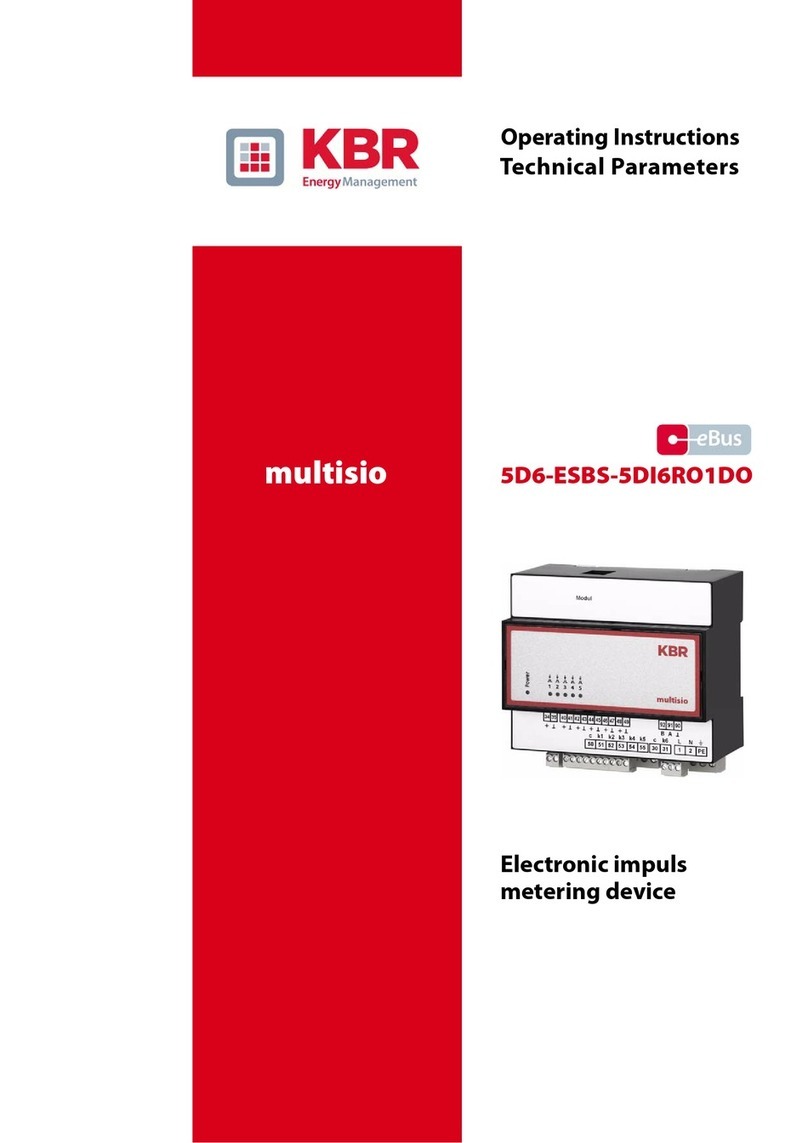
The multisio D6-ESBS-4RO ISO-1 with eBus hardware supports four oating relay outputs
(changeover relays), 5 LEDs and an 8-fold DIP switch.
The relay outputs serve to control contactors of devices or other systems.
The module can be accessed from a master device (multimax D6-5, multisio D6-7 or higher,
or a computer with visual energy via multigate ESBS) using the module bus interface. The
master device has to congure the module. The module cannot be used on its own
The bus interface is powered via a power supply (of Ph-N100V –240V+/-10% 50Hz/ 60Hz
AC or DC) or the module bus interface (24 VDC). The device is equipped with a “power” LED
for supply voltage monitoring.
NOTE
The expanded module bus interface (RS 485 serial) also functions as a gateway
(implementation of module bus RJ12 on eBus (ESBS)).
Prerequisite: Module bus input via RJ12 - connector
eBus output via terminal 93, 94, and 95
