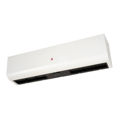
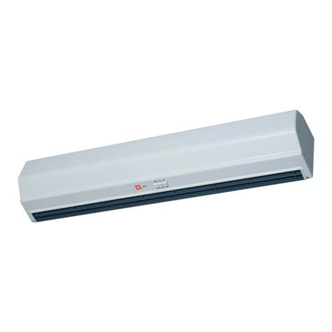
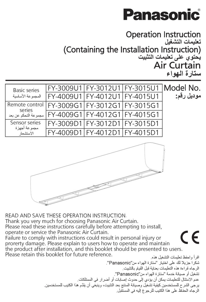
KDK Basic Series User manual

ﺕﻳﺑﺛﺗﻟﺍ ﺕﺎﻣﻳﻠﻌﺗ ﻰﻠﻋ ﻱﻭﺗﺣﻳ
ءﺍﻭﻬﻟﺍ ﺓﺭﺎﺗﺳ
:ﻡﻗﺭ ﻝﻳﺩﻭﻣ
ﺔﻳﺳﺎﺳﻷﺍ ﺔﻋﻭﻣﺟﻣﻟﺍ
ﺩﻌﺑ ﻥﻋ ﻡﻛﺣﺗﻟﺍ ﺔﻋﻭﻣﺟﻣ
ﺓﺯﻬﺟﺃ ﺔﻋﻭﻣﺟﻣ
ﺭﺎﻌﺷﺗﺳﻻﺍ
3009UA
4009UA
3009GA
4009GA
3009DA
4009DA
3012UA
4012UA
3012GA
4012GA
3012DA
4012DA
3015UA
4015UA
3015GA
4015GA
3015DA
4015DA
Basic series
Remote control
series
Sensor series
Model No.
.ﻩﺫﻫ ﻝﻳﻐﺷﺗﻟﺍ ﺕﺎﻣﻳﻠﻌﺗ ﻅﻔﺣﺍﻭ ﺃﺭﻗﺍ
." KDK" ﻥﻣ ءﺍﻭﻬﻟﺍ ﺓﺭﺎﺗﺳ" ﺭﺎﻳﺗﺧﺍ ﻰﻠﻋ ﻙﻟ ﻼﻳﺯﺟ ﺍﺭﻛﺷ
.ﺕﻳﺑﺛﺗﻟﺎﺑ ﻡﺎﻳﻘﻟﺍ ﻝﺑﻗ ﺔﻳﺎﻧﻌﺑ ﺕﺎﻣﻳﻠﻌﺗﻟﺍ ﻩﺫﻫ ﺓءﺍﺭﻗ ءﺎﺟﺭﻟﺍ
."KDK" ﻥﻣ ءﺍﻭﻬﻟﺍ ﺓﺭﺎﺗﺳ" ﺔﻣﺩﺧ ﺔﻧﺎﻳﺻ ﻭﺃ ﻝﻳﻐﺷﺗ
.ﺕﺎﻛﻠﺗﻣﻣﻟﺍ ﻲﻓ ﺭﺍﺭﺿﺃ ﻭﺃ ﺕﺎﺑﺎﺻﺇ ﺙﻭﺩﺣ ﻰﻟﺇ ﻱﺩﺅﻳ ﻥﺃ ﻥﻛﻣﻳ ﺕﺎﻣﻳﻠﻌﺗﻠﻟ ﻝﺎﺛﺗﻣﻻﺍ ﻡﺩﻋ
.ﻥﻳﻣﺩﺧﺗﺳﻣﻠﻟ ﺏﻳﺗﻛﻟﺍ ﺍﺫﻫ ﻡّﺩﻘﻳ ﻥﺃ ﻲﻐﺑﻧﻳﻭ ،ﺕﻳﺑﺛﺗﻟﺍ ﺩﻌﺑ ﺞﺗﻧﻣﻟﺍ ﺔﻧﺎﻳﺻﻭ ﻝﻳﻐﺷﺗ ﺔﻳﻔﻳﻛ ﻥﻳﻣﺩﺧﺗﺳﻣﻠﻟ ﺡﺭﺷﻟﺍ ﻰﺟﺭﻳ
.ﻝﺑﻘﺗﺳﻣﻟﺍ ﻲﻓ ﻪﻳﻟﺇ ﻉﻭﺟﺭﻠﻟ ﺏﻳﺗﻛﻟﺍ ﺍﺫﻫ ﻰﻠﻋ ﻅﺎﻔﺣﻟﺍ ءﺎﺟﺭﻟﺍ
READ AND SAVE THESE OPERATION INSTRUCTION.
Thank you very much for choosing KDK Air Curtain.
Please read these instructions carefully before attempting to install,
operate or service the KDK Air Curtain.
Failure to comply with instructions could result in personal injury or
prorerty damage. Please explain to users how to operate and maintain
the product after installation, and this booklet should be presented to users.
Please retain this booklet for future reference.
Operation Instruction
Air Curtain
ﻝﻳﻐﺷﺗﻟﺍ ﺕﺎﻣﻳﻠﻌﺗ
(Containing the Installation Instruction)

ﺕﺎﻳﻭﺗﺣﻣﻟﺍ
21 ......................................................................................................... ﺔﻣﻼﺳﻟﺍ ﺕﺎﻣﻳﻠﻌﺗ
21-22 ..................................................................................................... ﺕﻳﺑﺛﺗﻟﺍ ﺕﺎﻬﻳﺑﻧﺗ
23 ................................................................................................... ﺔﻘﺣﻠﻣﻟﺍ ﺕﺍﺭﺍﻭﺳﺳﻛﻹﺍ
23-24 ............................................................................................... ﺩﺎﻌﺑﻷﺍﻭ ءﺍﺯﺟﻷﺍ ﻡﺳﺍ
25 ......................................................................................................... ﺕﻳﺑﺛﺗﻟﺍ ﺕﺎﺑﻠﻁﺗﻣ
26-28 ........................................................................................................ ﺕﻳﺑﺛﺗﻟﺍ ﺔﻳﻔﻳﻛ
29 .................................................................................... ﺔﻋﻭﻣﺟﻣ ﻲﻓ ﺓﺩﺩﻌﺗﻣ ﺕﺎﺟﺗﻧﻣ ﻝﻳﻐﺷﺗ
29 .................................................................................................... ﻙﻼﺳﻷﺍ ﻁﺑﺭ ﻁﻁﺧﻣ
30-33 ...................................................................................................... ﻝﻳﻐﺷﺗﻟﺍ ﻕﺭﻁ
34-36 ....................................................................................................ﺔﻳﻧﻳﺗﻭﺭﻟﺍ ﺔﻧﺎﻳﺻﻟﺍ
37 .....................................................................................ﺎﻬﺣﻼﺻﺇﻭ ءﺎﻁﺧﻷﺍ ﻑﺎﺷﻛﺗﺳﺍ ﻝﻳﻟﺩ
38................................................................................................................ﺕﺎﻔﺻﺍﻭﻣﻟﺍ
Contents
Safety instructions ............................................................................ 2
Installation cautions ...................................................................... 3~4
Supplied accessories ......................................................................... 5
Parts name and dimensions .......................................................... 5~6
Requirement of installation ............................................................... 7
How to install ............................................................................. 8~10
Multiple products operation in group .............................................. 11
Wiring diagram ............................................................................... 11
Operation methods ................................................................... 12~15
Routine maintenance ................................................................ 16~18
Trouble shooting guide ................................................................... 19
Specification ................................................................................... 20

2
Safety instructions Please observes strictly
Those things shown in this column indicate that
there is possibility of causing death or severe injury.
Those things shown in this column indicate that there
is possibility of causing injury to the users or damage.
■Types of instructions that should be observed have been classified and described
by the following pictorial symbols.
The following Instructions should be strictly observed in order to prevent injury to
the users and other people, or damage to property.
■The degrees of injury or damage that can be occured when the instructions are
ignored and if the product is not used properly have been classified and described
by the following indications.
WARNING
CAUTION
This symbols indicates the
item is“PROHIBITED” to do.
This symbol indicates the
“COMPULSORY“ item that must
be followed without failure.
■If the supply cord is damaged, it must be replaced by the
manufacturer, its service agent or similarly qualified persons in order
to avoid a hazard.
■This product is not intended for use by persons (including children)
with reduced physical, sensory or mental capabilities, or lack of
experiences and knowledge, unless they have been given supervision
or instruction concerning use of the product by a person responsible
for the safety.
■Children should be supervised to ensure that they do not play with the
product.
■Make sure to disconnect the power plug before cleaning the product.

3
Installation cautions
■Connect the product to supplied
power by means of specified wire.
■A over load protection device must be
installed in the wiring when installing.
May cause fire or
electric shocks.
■It’s prohibited to install any other
substances with magnetic among the
diameter of 20m from gate magnetic
switch for sensor series.
It may result in fault or error
conditions caused by
magnetic disturbance.
The connection position of
terminal must be firmly fixed.
■Grounding should be connected.
May cause electric shocks.
■All installation and maintenance shall
be done by qualified persons.
Unqualified construction may
cause unexpected accidents.
EARTH WIRE
■Any other power supply other than
the rated voltage is prohibited to
use.
May cause fire or damage
the unit.
■Do not reconstruct this product.
Otherwise, it may cause
damage to the product or
injury.
Improper installation may cause
the product to fall off.
■Do not install the product as the
method which is not approved in the
instruction.
■It's prohibited to install the product in
locations such as machinery, chemical
plants or research facilities where it
will be exposed to noxious gases
containing acids, alkali, organic
solvents, paint fumes, etc., to gases
containing corrosive ingredients.
It could cause gas poisoning,
corrosion and degradation of
product that results in a fire.
■Use the screws with specified
quantity and diameter and fasten
them when hanging the product.
Otherwise the product may fall
down and it may cause injuries.
WARNING

Installation cautions
4
WARNING
■It’s prohibited to install in the following locations.
Locations such as bathroom
where it will produce
excessive humidity or vapor
with high humidity.
Location with
combustible gas or
emission of exhaust
gas.
Outdoor or locations that
could be sprayed by water.
It may cause an electrical shock
when condensation occurs in
the product, water drop results
in a short circuit.
Otherwise it may cause
a fire.
Water entersinto the product
that results in an electrical
shock or a short circuit.
Indoor Outdoor
■Secured upon the strengthened
foundations for installation. Be sure to
take reinforcement measures if
required for sufficient installation
strength.
Improper installation
may cause accident
because of the falling
of the product.
■Dedicated components must be used
for installation. (Include the
accessories)
Failure to use the dedicated
components that results in
dropping, a fire or an electrical
shock.
■The protective tools, gloves or helmet,
should be worn while inspection or
maintenance.
May cause injury or
burn.
■Product must be installed by two
persons.
Otherwise product may drop
that results in injuries.
CAUTION

Supplied accessories
The following accessories are provided with the air curtain in the package.When you unpack, check
if the accessories are all included.If any accessory is missing, please contact your dealer.
No.
Figure Name
Remote
control
series
Sensor
series
①Washer 6 6 6 ⑥Operation
instruction 1 1 1
②Spring
washer 6 6 6 ⑦Remote
control - 1 -
③6 6 6 ⑧Battery
(AAA battery)- 2 -
④Bolt
M8×60L 6 6 6 ⑨Support for
remote control - 1 -
⑤Screw - 2 4 ⑩Gate magnetic
switch - - 1
No.
Figure Name
Basic
series
Remote
control
series
Sensor
series
Nut
(M8)
Basic
series
Quantity Quantity
Parts name and dimensions
■Front view of basic series
■Back view of basic series
■Front view of remote control series
■Back view of remote control series
Eight holes (8mm wood screw)
Six holes (M8 bolts)
Direction
of
Air outlet
Unit :mm
Power supply cord
■Right view of basic series
■Right view of remote
control series
5
Six holes (M8 bolts)Power supply cord
Direction
of
Air outlet
A
5
6
7
1
8 2 13
3
212
231.5
4
250 250 250
B400 400 B
62120
22
170
A
567
1
2 13
3
212
4
231.5
250 250 250
B400 400 B
62120
22
170
Eight holes (8mm wood screw)
10 12
11

6
■Front view of sensor series
■Back view of sensor series
Please refer to the table above to recycle the materials as much as possible
when discarding this product.
■Right view of sensor series
A
900
1200
1500
B
50
200
350
Model No.
3009UA , 4009UA
3012UA , 4012UA
3015UA , 4015UA
3009GA , 4009GA
3012GA , 4012GA
3015GA , 4015GA
900
1200
1500
50
200
350
No.
1
2
3
Part name
Resin ABS
Classification
Front panel
Air outlet
Mounting plate Steel SGCC
4Back panel Steel SGCC
5
6
7
Assembly partMotor
Motor support
Cross-flow impeller
8Push –button switch
Steel plate +ResinAS
+Glass fiber
9
10 Remote control
11 Touch switch
Resin ABS
12
Guide plate13
Parts name and dimensions
Gate magnetic switch
3009DA , 4009DA
3012DA , 4012DA
3015DA , 4015DA
900
1200
1500
50
200
350
Basic series
Remote control series
Sensor series
No. Part name Classification
Support for
remote control
Assembly part
Assembly part
Assembly part
Resin ABS
Steel SGCC
Assembly part
Resin ABS
NOTE
Eight holes
(8mm wood screw)
Six holes (M8 bolts)Power supply cord
Direction
of
Air outlet
A
567
1
8 2 13
3
212
231.5
4
250 250 250
B400 400 B
62120
22
170
9

7
Requirement of installation
■It’s prohibited to install in the following locations.
Locations with temperature
exceeding 40℃or less than -10℃.
Locations where freezing could happen.
(Such as refrigerators)
It’s prohibited to install in the uneven
surface.(Flatness shall be 3mm below.)
It may cause a fire.
40℃ Distortion results in reducing
the separation performance.
Factory, kitchen or other locations
where cooking fumes is produced.
Locations with heavy sand and dust.
Blade deformation may be caused by
sand and dust piling up in impeller may
affect the performance.
cooking
fumes
■The lowest surface of this product
should be mounted above 2.3m from
the floor after installation.
■The distance between product and
ceiling must be 50mm above.
The ceiling is excessively close
to air inlet that may reduce the
separation performance.
■Please install the product horizontally,
don’t vertically install the product.
It could affect the performance
of bearing.
■Ensure the space among products is
20~40mm when multiple products
operating in row.
■Please block the clearance between
wall and product by means of partition
plate.
Prevent product
from sucking out
door air from
clearances.
50mm above
20~40mm
2.3m above
Easy for installation.
Touching the product
may result in injury.

How to install
8
1.Fix the mounting plate
■Mounting on concrete wall.
1.Remove mounting plate from product.
Taking the mounting plate by removing
the screws.
2.Firmly fix the bolts in the proper position.
·Determine the position on the wall and drill into the wall.
·Fit the bolts into the holes.
·Fill the holes with concrete.
·Install the mounting plate and check,
if it’s secured when the concrete solidifies.
※Distance of bolt head away from wall
should be 13~15mm.
3.Fix the mounting plate with washers,
spring washers and nuts.
■Please use the mounting plate provided
with product to avoid the dropping
caused by insufficient strength.
■The wall should be constructed so
that it can support more than 5 times
of the weight of product. Ensure to
reinforce the wall when withstanding
strength can’t be confirmed.
Otherwise product may drop that
results in injuries.
ScrewMounting plate
Mounting plate Washer
Nut
Spring
washer
Mounting
plate
■Other installation methods:
Mounting on steel hanger
M8 bolt
15mm below
Mounting on wooden frame
Wood screw
(Φ8×60L)
1.It’s prohibited to install the product on hollow wall, otherwise it may produce noises.
2.Conduct the necessary reinforcement, depending on the particular condition to avoid noise
resonance and vibration.
Concrete
About
Diameter
NOTE
CAUTION

How to install
Pre-hang up the product
into the hook of mounting
plate.
※Carry out this step if the distance between top face of
product and ceiling is less than 150mm.
Hook
150mm above
2.Preparation before wiring
■Connect the power cord to the power supply line according to the wiring
diagram and the local electrical wiring rules of fixed wiring.
■Use this product at the rated voltage and frequency indicated on the
name plate.This may damage the product or result in fire.
■Do not damage the insulation paste of the power cord.
■Please follow the figure below to strip sheath of wire, too long wirestripping
may cause a short circuit or a fire.
■The all connections should be accommodated in a suitable compartment.
■Use a device for disconnection from the supply, which having a contact
separation of at least 3mm in all poles (switch), which must be incorporated
in the fixed wiring in accordance with the local eletrical wiring rules.
Short circuit may result in fire.
■It is required to use terminal (not supplied) that complies IEC 60998.
■Make sure all connections are fastened firmly after wiring is finished.
3.Wiring
1.Follow the figure below to strip sheath of wire.
2.Green/yellow wire within power supply cord for product is
earth wire, please confirm ground connection during construction.
3.Connect the power supply cord of product to that of supplied power
as shown in figure. (Include the earth wire)
Unit :mm
Figure for striping skin of wire
Earth wire
20-30
30-40
10
10
■Minimum cross-section area of power supply cord of supplied power is 1.0mm .
Power cord
of product
Power supply cord
Air curtain
※It’s required to check if all connection is firmly fastened after completion of wiring.
Refer to the wiring :
Power cord
of product
Green/Yellow
(Earth wire)
Earth wire
Power supply cord
Terminal block
(Prepared by Customer)
Live
(L)
Neutral
(N)
Brown
(L)
Blue
(N)
2
9
WARNING

How to install
10
4.Installation of product
1.Place the product on the mounting plate.
2.Adjust the position of the product.
Align the groove of back panel with both sides of
mounting plate. Fit the holes into the hook from
mounting plate.
3.Fasten the screws. (3 places)
※The torque is suggested
to be 1.2N·m.
Back panel
Mounting plate
■Product should be installed by
2 persons.
Otherwise, the product
may fall down and it may
cause injuries.
Groove
5.Installation of sensor
1.Place the sensor with wire on top of door. Fix the sensor with screws.
2.Place the other sensor under the sensor with wire,
the distance between them should
be 8mm below, as shown in figure.
If the magnet part fixed on steel or
iron doors, the distance should
be 5mm below.
3.Connect the sensor and main body
and wrap it with insulation tape.
1.When connection is complete, please do the trial operation.
If it works normally, follow the next step. If sensors still don’t work, adjust the distance to work
normally.
2.After the trial operation, fix the wire with groove or cord clip to make sure the wire is fastened
so that it will not be damaged by door movement.
3.For sliding door, the door with sensor should keep over 10mm from the door at the same side
to protect against the damage.
4.For glass door, stick the sensor with double adhesive tape.
NOTE
Shadow area is
wrapped with
insulation tape.
Conected to
main body
Connected to
sensor
CAUTION
Mounting
plate
The power cord and the
sensor wire should laid
apart,withe a distance
above 150mm.
Power cord
Sensor wire
(About 2000mm
from bushing to
connector)
8mm below

Multiple products operation in group
Wiring diagram
Wiring for operation of multiple products in parallel
Power supply cord
●Please purchase necessary parts following with local electrical requirements.
■Please follow with below figures to conduct the wiring.
■Remote control series ■Sensor series
■Basic series
■Please select the switch of whose capacity has 1.2~1.5 times of power
supply cord. When multiple products operate.
■Earth leakage breaker protector should be equipped, otherwise it may
cause an electrical shock.
■The number of interlocking operation is not more than 6.
11
Red
Black
White
(
H
)
Yellow
(
L
)
Yellow
White
Black
Capacitor
Motor
Switch
Power
TERMINAL
Source
Orange
Blue
Double Pole Switch
Customer Provide
(Contact Point SeparateDistance Over 3mm)
Green/Yellow
N
L
N
L
Brown
9P
Buzzer
SWITCH PCB
Receiver
Red
Lamp
Lo Red
Lamp
Hi
Blue
Power
Source
Brown
Blue
Brown
N
L
Green/Yellow
Black
Black
N
L
Yellow
Switch
ESwitch
E
White
White
Yellow
(L)(H)
Red Capacitor
Motor
MOrange
Terminal
MAIN PCB
TAB-L
TAB-N
1P
9P1P
5P1P 5P1P
Double Pole Switch
Customer Provide
(Contact Point
SeparateDistance
Over 3mm)
Magnet
3P
3P SWITCH PCB
Blue
Power
Source
Brown
Blue
N
L
Brown
Green/Yellow
Black
N
L
Black
Yellow
Piano
switch
White
White
Yellow
(L)(H)
Red
Red
Capacitor
Motor
MOrange
Terminal
Common Open
TAB-L
TAB-N
1P
1P
5P
5P
1P
1P
Double Pole Switch
Customer Provide
(Contact Point
SeparateDistance
Over 3mm)
WARNING

12
Operation methods
■Basic series
Operation of Control panel
Start to operate
1
2
3
Select the mode of operation
Stop operating
OFF
Press “HI”or“LO” button to start the product
as shown in left figure.
Press “HI” button if high air velocity is
required.
Press “LO” button if quiet operation and low
velocity is required.
The product is in stand-by mode after pressing the “OFF”.
Press “OFF” button to stop the product.
LO HIOFF
LO HIOFF
LO HIOFF
※Interlocking operation of gate magnetic switch
Sensor series are controlled to operate or stop by magnetic switch.
The gate magnetic switch works only when “HI” or “LO”are pressed.
Product will operate when both magnetic switch are separated.
Product will stop when both magnetic switch are within specific distance.
After 10 seconds of delay operation.
LO HI
■Sensor series
NOTE
OFF LOW HIGH
※Representative model
4009UA

13
Operation methods
Operation of Control panel
Start to operate
1
2
3
Select the mode of operation
Stop operating
Press “AIR VOLUME ” button to start the product
as shown in left figure.
Press the
“AIR VOLUME ”
to shift air volume.
The signal light for
air volume turns off.
The product is in stand-by mode after pressing
“STAND-BY”button, at this moment, it’s still connected
with power.
High air velocity is required.
Quiet operation and low air
velocity is required.
Press “STAND-BY” button to stop the product.
Operation of Remote control
LOW
HIGH
NOTE
Remote control series
Signal light for low operation Signal receiver
Signal light for high operation
The button in control panel can be operated for emergency in case
if remote control is not avaliable. Please operate with fingers
other than sharp or hard substances. Pay attention to the dangers
while operation in high level.
Press “HI” or “LO”button
to start.
STAND-BY
LOW
HIGH
NOTE
※Representative model
3009GA

14
Operation methods
Operation of remote control
Please hold the remote control toward the signal receiver
and use it within 5m from the signal receiver at angle
of 30° as shown below.
Signal receiver
Remote control
NOTE
The remote control should
be used with product in same room.
Setting of battery for remote control
1.Open the back cover.
2.Put the 2 batteries provided
into remote control.
3.Close the back cover.
Back cover
of remote
control Remote
control
Battery
(note the direction
of )
NOTE
■Don’t reverse the direction of .
■Don’t mix old battery with new one.
■Remove batteries if they are not to be used for a long time.
Related safety cautions concerning
the use of battery
Wrong use of battery could result in
liquid leakage, heating or breakage which
resultsin injuries or malfunction of product,
please comply with the following items.
■Wash immediately thoroughly with large
amount of water without rubbing if alkaline
liquid enters into your eyes and then get medical
treatment. Otherwise it could lead to blindness.
■Battery should not be placed in position where
infants and young children could reach.
Once swallowed, please get medical
treatment immediately.
■Don’t discard the battery into fire, and heating,
decomposition or self-transformation is also
prohibited. It could lead to liquid leakage,
heating or breakage if damaging the insulation
substances or exhaust valve.
■Don’t tear the outer packing of battery.
WARNING
CAUTION
Fix the support for remote
control at 1.5m height away
from the ground, and put the
remote control into the
support. (only applied to
remote control series)
20mm
Signal transmitter

15
Operation methods
1
2
3
■Guide vane in air outlet can be adjusted according to service environment to reach the
ideal separation performance.
light wind
in outdoor
Strong wind
in outdoor
Hot inside
Air outlet Guide vane
Air outlet
Guide vane
Air outlet Guide vane
Cold outside
While Strong wind in outdoor
While light wind in outdoor
Heating
4
Air outlet Guide vane
Cooling
Air outlet Guide vane
1.Room has opening
(window, grille, etc.)
2.Room is air tight
(no opening)
Cold
inside
Hot
outside
Cold
inside
Hot
outside

Routine maintenance
■Before touching this product, ensure
that the power switch connected to
this product is turned off.
This may result in electric
shock.
■Be sure to uninstall the product if it
will not be used any longer.
The product may fall off.
■Please contact entrusted distributor
where you purchased or qualified
persons to service the product.
Otherwise it may cause
injuries or an electrical shock.
■In case of gas leakage, do not turn on
/off this product.
■Don’t turn on or off the power with
wet hands.
It may cause a electrical shock.
■It’s prohibited to place the burning
appliances in a position where product
directly blows.
It may result in carbon
monoxide poisoning
caused by incomplete
combustion.
■Don’t be wetted or watered.
(electrical component such as motor
and switch)
■It’s prohibited to insert fingers or
sticks into the product, air inlet or
outlet.
Impeller at high speed
rotation may cause injuries.
It may cause short circuit
or electrical shock.
■Immediately stop to wait for repair if
abnormities happen (noise, vibration,
smell).
It may cause the unexpeted
accidents.
■Please wear the gloves during
maintenance.
Otherwise it may result in injuries.
■It’s prohibited to directly spray the
product with water or any other liquids.
It may cause short circuit or
electrical shock.
■It’s forbidden to hang anything on
the product.
Product may drop due to
the increased weight.
16
WARNING
CAUTION
This may generate electric spark
and lead to an explosion.

Routine maintenance
■Two persons are required
to conduct the maintenance.
Otherwise product may drop
results in injuries.
■Eyes should not be faced to the outlet
opening (specially when the fan stars
up).
Any flying substance may get
into the eyes.
■Please don’t place the substances
near to the air outlet or inlet grille.
It may result in personal
injuries due to blowing out
or sucking in.
■The strong air from air curtain may
cause the sand and dust.
Otherwise dropping caused by
corrosion of product may result
in personal injuries.
■It’s prohibited to wash with the
chemical agent and detergent as
shown in the following.
■Disassembly of part
This part can be easily taken
out by removal of 7 screws
as indicated in the following.
It may result in personal
injuries.
■Please ensure to disconnect from supply mains by
the double pole switch before cleaning and
maintaining the product, otherwise it may cause
electrical shock.
17
Metallic brush
Thinner
Gasoline
Volatile oil
■If the supply cord is damaged, it must
be replaced by manufacturer, its
service agent or similarly qualified
persons in order to avoid a
hazard.
NOTE
CAUTION

Routine maintenance
△△△△△△△△△△
△△△△△△△△△△
△△△△ △ △ △ △ △
△ △ △ △ △ △ △ △
● ● ● ●
●●●●●●●●● ●
●●●●●●●●● ●
●
●
●
●
To safely use the product in a long time, please follow these items below.
1)Note that all screws don’t work loose. It tends to cause vibration, dropping or a fire.
2)Motor is intended to use for about 20000 hours. But the actual life of motor may vary
depending on service environment.
3)Maintenance should be done by entrusted distributor or repair shop to service the
product.
Please refer to the table below to maintain the product. (The service life may be shorter
depending on service environment)
Routine maintenance can keep the efficiency of operation, may prevent increase of
energy loss and extend the service life of product.
Mainly maintain the
motor and impeller.
Mainly note the
noiseand vibration.
△△
Maintenance key points
18
■Routine Maintenance
Check point
Situation of operation.
Abnormal noise or vibration.
1.Maintenance period is affected by service time and service environment.
2.Generally service time :10 hours for a day, 300 days for a year, 3000 hours
in total.
3.Please contact with the distributor or repair shop regarding to cleaning,
replacement.
Gate
magnetic
switch
Motor
Impeller
Front
panel
Part
△Maintenance ●Cleaning ○Replacement.
1st
year
2nd
year
3rd
year
4th
year
5th
year
6th
year
7th
year
8th
year
9th
year
10th
year
Remove dirt.
Remove check dirt, noise
and vibration.
Noise, vibration.
Remove dirt.
■Maintenance period
Parts work loose such as
terminalblock or screws.
Rust or corrode of metal parts
such as motor, screw, etc..
Every
day
Every
month
Every
half year
Every
year
Maintenance period
Remarks
NOTE
Fasten screws.
Conduct the
replacement.

Trouble shooting guide
19
Condition 1st Possible reason 2nd Possible reason 3rd Possible reason
Can't operate. Check the voltage. Wiring is not correct. The remote control
don’t equip
with battery.
With large noise
or significant
vibration.
Installed not properly.
(P8~P10)
Poor separation
performance.
Not suitable model. Guide vane is not in
proper position.
(P15)
Product is installed
vertically.
Can’t operate. Wiring is not fixed. Double pole switch
became off.
Poor separation
performance.
Air inlet grille is
blocked.
With large noise
or significant
vibration.
Dust piles up in
impeller.
Any other substances
fell into the product.
Motor is abnormal.
Primary PeriodDuring operation
Magnetic
switch doesn’t
work.
Any other magnetic
substances near to
gate magnetic switch.
(P9)
Wiring is not
properly connected.
Magnetic
switch doesn’t
work.
Wiring is not
properly connected.
Any other magnetic
substances near to gate
magnetic switch.
Firstly check the following items, if malfunction still can’t be solved, please
disconnect from supply mains and contact with distributor and repair shop.
Double pole switch
became off.
(P9)
(P9)
This manual suits for next models
19
Table of contents
Other KDK Heater manuals
Popular Heater manuals by other brands

Accorroni
Accorroni FR-FC-FCO-FCR Series technical information

Beper
Beper RI.132 Use instruction

Adler Europe
Adler Europe AD 7726 user manual

Creda
Creda CLR5C Installation and operating instructions

Omega Altise
Omega Altise AHPE222W Operation, maintenance and safety instructions

Modine Manufacturing
Modine Manufacturing POR oil-fired unit installation instructions

Dyna-Glo
Dyna-Glo EG5000DGC Installation & maintenance instructions

Joyside
Joyside JS-OH-Z03 Series instruction manual

Truma
Truma Ultraheat S 3004 installation instructions

Alpina
Alpina YL-A07S-7 instruction manual

BriskHeat
BriskHeat XtremeFLEX HSTAT-R Series instruction manual

Bimar
Bimar S707.EU Instruction book