FOR-A VTW-350HS User manual

OPERATION
MANUAL
VTW-350HS
Video Type Writer
1st Edition
USO RESTRITO

2
Edition Revision History
Edit.
Rev.
Date
Description
Section/Page
1
-
2014/09/17
USO RESTRITO

3
Precautions
Important Safety Warnings
[Power]
[Grounding]
Caution
Ensure the unit is properly grounded at all times to prevent electricalshock.
Hazard
Do not ground the unit to gas lines, units, or fixtures of an explosive or dangerous
nature.
Caution
Ensure the power cord is firmly plugged into the AC outlet.
[Operation]
Hazard
Do not operate the unit under hazardous or potentially explosive atmospheric
conditions. Doing so could result in fire, explosion, or other hazardousresults.
MHazard
Do not allowliquids,metal pieces, or other foreign materials to enter the unit. Doing
so could result in fire, other hazards, or a unit malfunction.
If a foreign material does enter the unit, turn the power off and immediately
disconnect the power cord. Remove the material and contact an authorizedservice
representative if damage has occurred.
[Transportation]
Handle with care to avoid impact shock during transit, which may cause
malfunction. When you need to transport the unit, use the original or suitable
Caution alternative packing material.
Caution
Operate unit only at the specified supply voltage.
Disconnectthe powercordvia the powerplug only. Do not pull on the cable portion.
Stop
Do not place or drop heavy or sharp-edged objects on the power cord. A damaged
cord can cause fire or electrical shock hazards. Regularly check the power cord for
excessive wear or damage to avoid possible fire / electrical hazards.
USO RESTRITO

4
[Circuitry Access]
Do not remove covers, panels, casing, or access the circuitry with power applied to
the unit. Turn the power off and disconnect the power cord prior to removal. Internal
servicing / adjustment of unit should only be performed by qualifiedpersonnel.
Stop
Do not touch any parts / circuitry with a high heatfactor.
Capacitors can retain enough electric charge to cause mild to serious shock, even
after the power has been disconnected. Capacitors associated with the power
supply are especially hazardous.
Hazard
Unit should not be operated or stored with cover, panels, and / or casing removed.
Operating the unit with circuitry exposed could result in electric shock / fire hazards
or a unit malfunction.
[Potential Hazards]
[Rack Mount Brackets, Ground Terminal, and Rubber Feet]
[Consumables]
Consumable items that are used in the unit must be periodically replaced. For
further details on which parts are consumables and when they should be replaced,
refer to the specifications at the end of the Operation Manual. Since the service life
of the consumables varies greatly depending on the environment in which they are
Caution used, such items should be replaced at an early date. For details on replacing
consumable items, contact your dealer.
To rack-mount or ground the unit, or to install rubber feet, do not use screws or
materials other than those supplied. Doing so may cause damage to the internal
circuits or components of the unit. If you remove the rubber feet that are attached to
Caution the unit, do not reinsert the screws that secure the rubber feet.
If abnormal odors or noises are noticed coming from the unit, immediately turn the
power off and disconnect the power cord to avoid potentially hazardous conditions.
If problems similar to the above occur, contact an authorized service representative
Caution before attempting to operate the unit again.
USO RESTRITO

5
Upon Receipt
Unpacking
VTW-350HS Video Typewriter units and their accessories are fully inspected and adjusted prior to
shipment. Operation can be performed immediately upon completing all required connections and
operational settings.
Check your received items against the packing listsbelow.
ITEM
QTY
REMARKS
VTW-350HS
1
AC Cord
1 set
One AC cord and one AC cord retaining clip
Rack Mount Brackets
1 set
EIA standard type
Rubber Feet
1 set
DVI (29-pin)-VGA
conversion adapter
1
For VGA monitor connection
CD-ROM
1
VTW-350HS Operation manual (PDF)
VTW Software manual (PDF)
* The monitor, the keyboard, and the mouse for controlling VTW-350HS are available for the
separate purchase.
IMPORTANT
Do not install any additional software on the VTW-350HS. It may cause system
malfunction.
Toturn off the VTW-350HS, shut down Windows and then press the power switch on
the front of the unit.
When turning back on the VTW-350HS after powering off, wait at least 10seconds.
Check
Check to ensure no damage has occurred during shipment. If damage has occurred, or items are
missing, inform your supplier immediately.
Trademark
Microsoft ® Windows ® 7 Embedded operating system is a trademark of MicrosoftCorporation.
Rack Mounting
The VTW-350HS can be mounted to EIA standard rack units. When rack mounting a unit, use the
supplied rack mount brackets (rack ears).
USO RESTRITO

6
Table of Contents
1. Prior to Starting ...........................................................................................................................7
1-1.Welcome ..............................................................................................................................7
1-2. Features...............................................................................................................................7
2. Panel Descriptions ......................................................................................................................8
2-1. Front Panel...........................................................................................................................8
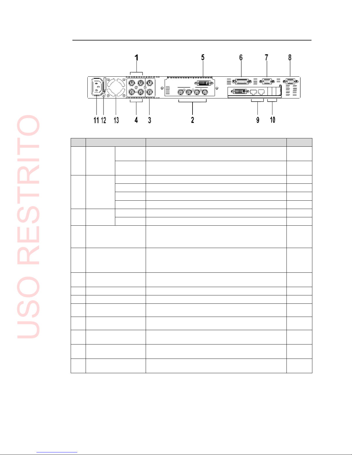
2-2. Rear Panel ...........................................................................................................................9
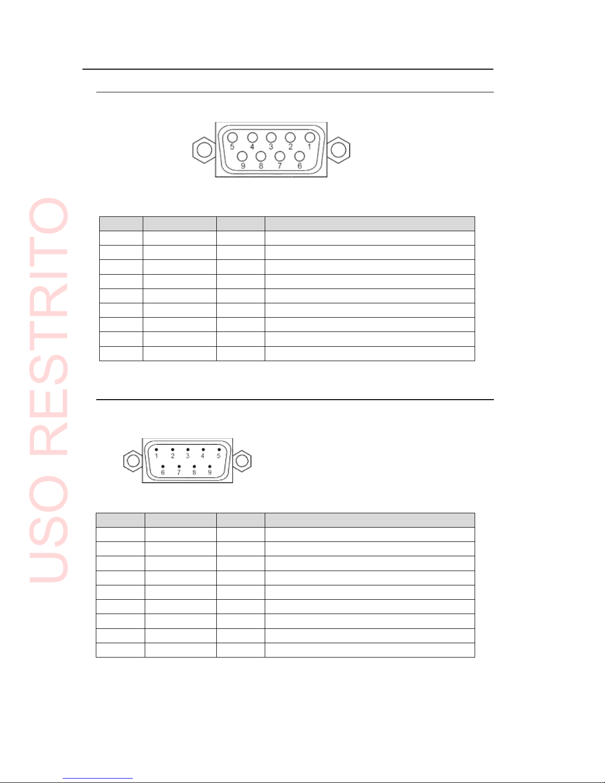
2-3. Serial Interfaces.................................................................................................................10
2-3-1. Remote........................................................................................................................10
2-3-2. RS-232C .....................................................................................................................10
2-4. Parallel Interface................................................................................................................11
2-4-1. GPI / ALARM...............................................................................................................11
3. Connections...............................................................................................................................14
3-1. Connecting Monitor, Keyboard, and Mouse ......................................................................14
4. System Adjustment ...................................................................................................................15
4-1. Selecting Genlock Signal and Adjusting Phase.................................................................15
4-2. Output Settings ..................................................................................................................17
5. Specifications and Dimensions.................................................................................................18
5-1. Unit Specifications..............................................................................................................18
5-2. External Dimensions..........................................................................................................19
Appendix. How to Reset BIOS......................................................................................................20
1. Opening the BIOS Setup Menu.............................................................................................20
2. Main Menu Settings...............................................................................................................21
3. Configuration Menu Settings.................................................................................................22
4. Boot Menu Setting.................................................................................................................25
5. Saving Settings and Exiting BIOS Setup Menu....................................................................25
USO RESTRITO

7
1. Prior to Starting
1-1. Welcome
Congratulations! By purchasing VTW-350HS Video Typewriter you have entered the world of
FOR-A and its many innovative products. Thank you for your patronage and we hope you will
turn to FOR-A products again and again to satisfy your video and audioneeds.
FOR-A provides a wide range of products, from basic support units to complex system
controllers, which have been increasingly joined by products for computer video based systems.
Whatever your needs, talk to your FOR-A representative.We will do our best to be of continuing
service to you.
1-2. Features
VTW-350HS is a low cost HD/SD Video Typewriter. With its lightweight, compact design, the
VTW-350HS is an extremely portable video typewriter perfect for relay applications. The
software offers a rich array of drawing functions, more than 260 transition functions, template
control, general-purpose file interface and more.
All the functions you need are packed into an extremely compact case. With its excellent cost
performance, the VTW-350HS makes CG production affordable forall.
More than 260 transition functions come standard, including roll, crawl, fade in, fade out,
slide and wipe
1U size compact design excellent for relay applications. The vibration-resistant case
makes it perfect for portable and on-boardapplications
Capable of capturing and storing still images from SDI inputs (video and key signals can
be stored simultaneously)
Program and preview outputs
USO RESTRITO

8
2. Panel Descriptions
2-1. Front Panel
No.
Name
Description
1
Status
Indicators
POWER
Lit green
Power is supplied to the unit.
Unlit
The unit is powered off or power cord is not
plugged in properly.
ACT
Not used
FAN
Unlit
All cooling fans are operating properly.
Lit red
One or more fans failed. Power off the unit and
replace the failed fan, if necessary.
2
Power
switch
Power
indicator
Switch used to turn unit power ON / OFF.
Power indicator will be lit green when power switch is turned ON.It
takes about 5 seconds for the indicator to be lit. Wait at least 10
seconds to turn ON after power switch is turnedOFF.
Be sure to shut down Windows before turning OFF this powerswitch.
3
USB1
USB2
Used to connect USB devices such as a keyboard, mouse, and other USB
devices (USB2.0).
4
RESET
If the POWER indicator does not light up green 5 seconds after thepower
switch is turned on, press the RESET switch (Not for normal use.).
IMPORTANT
If the FAN indicator lights up red, there is a fan failure. Turn off the VTW-350HS and
contact your retailer.
VTW-350HS
VIDE O TYPEW RITE R
POWER
POWER ACT FAN
ON
USB 1 USB 2
RESET
OFF
USO RESTRITO

9
V
K
PGMV2
PGMK2
GPI/ALARM
RS-232C
REMOTE
DVI-I
OUTPUT
PGMV1 PGMK1 PREV V PREV K
GENLOCK IN
DVI-I
LAN2 LAN1 USB4USB3
2-2. Rear Panel
No.
Name
Description
Refer to
1
INPUT
V
HD/SD SDI Video input with built-inframe
synchronizer, BNC
K
HD/SD SDI Key input with built-in framesynchronizer,
BNC
2
OUTPUT
PGM V1
HD/SD SDI program (On-air) output (Video), BNC
PGM K1
HD/SD SDI program (On-air) output (Key), BNC
PREV V
HD/SD SDI Preview output (Video), BNC
PREV K
HD/SD SDI Preview output (Key), BNC
3
OUTPUT
PGM V2
Program distribution output (Video), BNC
PGM K2
Program distribution output (Key), BNC
4
GENLOCK IN
External reference signal input (Black Burst signal or
Tri-level sync signal), BNC
(Terminate with 75Ω terminator, if unused.)
3
5
DVI-I
For digital monitor connection.
Use the supplied adapter for VGA monitorconnection.
Bottom DVI-I connector is unavailable.
6
GPI / ALARM
For power / fan alarm output and the GPIinput/output.
(15-pin D-sub, female)
2-4-1
7
RS232C
RS-232C serial port. 9-pin D-sub, male
2-3-2
8
REMOTE
RS-422 serial port. 9-pin D-sub, female.
2-3-1
9
LAN
1
LAN
2
For the connection to a computer Ethernet port.
(100BASE-TX/1000BASE-T, RJ-45)
10
USB3
USB4
For the connection to USB devices such as a keyboard,
mouse, and other USB devices (USB 3.0).
3-1
11
AC IN
For the connection to AC power source via supplied
accessory cord. (100-240VAC 50/60Hz)
12
Ground Terminal
For grounding unit to protect operators against static
electricity and / or electrical shock.
13
Cooling Fan
For cooling unit to prevent overheating. Do notblock
the vent with other equipment or objects.
AC10 0 - 24 0V 5 0/6 0Hz I N
SE R. N O .
INPU T
OUTPU T
USO RESTRITO

10
2-3. Serial Interfaces
2-3-1. Remote
The remote connector is normally notactive.
9-pin D-sub, female
Pin Assignment
Pin No.
Signal
I/O
Description
1
FG
-
Frame ground
2
TX-
Out
Transmit data (-)
3
RX+
In
Receive data (+)
4
SG
Signal ground
5
NC
No connection
6
SG
Signal ground
7
TX+
Out
Transmit data (+)
8
RX-
In
Receive data (-)
9
FG
Frame ground
2-3-2. RS-232C
9-pin D-sub, male
Pin Assignment
Pin No.
Signal
I/O
Description
1
DCD
Detect carrier detect
2
RXD
In
Receive data
3
TXD
Out
Transmit data
4
DTR
Out
Data terminal ready
5
GND
Signal ground
6
DSR
In
Data set ready
7
CTS
In
Clear to send
8
RTS
Out
Request to send
9
RI
Ring indicator
USO RESTRITO

11
2-4. Parallel Interface
2-4-1. GPI / ALARM
15-pin D-sub, female
Pin Assignment
Pin No.
Signal
I/O
Description
VTW function
1
GND
-
Signal ground
2
POW ALARM
Out
Power alarm output (*1)
3
FAN ALARM
Out
Fan alarm output (*1)
4
NC
-
Not used
5
GPI IN3
In
GPI input(*2)
Pause
6
GPI IN2
In
GPI input (*2)
Stop / Clear
7
GPI IN1
In
GPI input (*2)
Play
8
+5VOUT
Out
+5V DC output
9
COMMON
-
Power/fan alarm output,
common (*1)
10
NC
-
Not used
11
NC
-
Not used
12
GPI IN4
In
GPI input (*2)
Cut
13
GPI OUT2
Out
GPI output(*3)
(No use)
14
GPI OUT1
Out
GPI output(*3)
(No use)
15
GND
-
Signal ground
* The maximum current rating for +5V output is 200mA.
(*1) See "Alarm Output Circuit" in the following page.
(*2) See "GPI IN Circuit" in the following page.
See “VTW Software Operation Manual” for function assignments.
(*3) See "GPI OUT Circuit" in the following page.
See “VTW Software Operation Manual” for function assignments.
USO RESTRITO

12
Alarm Output Circuit
Normally open relay circuit. The circuit behaves asbelow.
When operating normally:
An alarm pin and the common pin are open.
When a malfunction occurs or the power is off:
An alarm pin and the common pin are closed.
Pin 9 is a common pin for both power alarm and fanalarm.
Contact rating is 0.5A@30VDC
Alarm Output VTW-350HS Max:30V
Closed when a
malfunction
occurs or power
is off.
Relay contact
Relay contact
Pow Alarm
Fan Alarm
Common
GPI IN Circuit
Pulse level trigger type. GPI IN pin and GND pin change the state from open toclose.
Pulse width: 100msec or more, pulse interval: 100msec ormore.
GPI IN1 (Pin7)
From open to closed position
Enables the assigned function
GPI IN pulse More than 100msec More than 100msec
OPEN
CLOSE
GPI IN
VTW-350HS
GPI IN1-4
GND
More than 100msec
USO RESTRITO

13
GPI OUT Circuit
Open collector output.
When using an external power source, its voltage should be 12V orless.
The output current of each GPI OUT pin should be less than20mA.
GPI OUT1 (Pin14)
When function is ON:
The pin and the ground pin are shorted.
When function is OFF:
The pin and the ground pin are open.
GPI OUT
VTW-350HS
Max: 12V
GPI OUT1-2
GND
USO RESTRITO

14
3. Connections
Connect peripherals as depicted below.
LINE VIDEO
(HD/SD SDI)
LINE KEY
(HD/SD SDI)
On air
Preview
BB/Tri sync
Loopthrough
On-air signals
monitoring
IMPORTANT
USB ports are provided for connecting a keyboard and a mouse. If you are using a
PS/2 mouse and PS/2 keyboard, use USB-PS2adapters.
VTW-350HS with providedframe synchronizer doesnotneed to have reference signal
in GENLOCK INconnector.
3-1. Connecting Monitor, Keyboard, and Mouse
Before starting the VTW Software, connect a monitor, keyboard and mouse as shown below.
(The monitor, keyboard and mouse need separate purchase.)
VTW-350HS
VTW-350HS
Input V
VIDEO
PGM1
Input K
KEY
VIDEO
PREV
KEY
VIDEO
GENLOCK IN
PGM2
KEY
GPI/ALARM
RS-232C
RE MOTE
V K
P GMV 2
DV I-I
OUTP UT
PGMV1 PGMK1 P REV V P REV K
P GMK 2
GENLOCK IN
DVI-I LAN2 LAN1 USB4 USB3
DVI cable
Mouse
USB cable
Keyboard
USB cable
AC10 0 - 2 40V 50 /6 0Hz I N
SE R. N O .
IN PU T
OUTPU T
USO RESTRITO

15
4. System Adjustment
The dedicated utility software, FOR-A MBP Utility allows you to select a genlock signal, adjust the
genlock phase, select a mix mode and set to mix the text on thevideo.
IMPORTANT
Touse the FOR-A MBP Utility, connect a monitor, a mouse and akeyboard.
The FOR-A MBP Utility and the VTW software cannot be run on the VTW-350HS at
the same time.
4-1. Selecting Genlock Signal and Adjusting Phase
1. Exit the VTW software.
2. Double-click the FOR-A_MBP_Utility icon on the desk top to start theapplication.
3. The FOR-A_MBP_Utility starts up, and the Info page opens. In the Info page, the
information about the installed boards can be seen.
4. Select Genlock tab.
5. Select a Video format to set the genlock.
6. Select a Genlock format.
BB
Black burst
TRI
Tri-level sync
7. Genlock status is indicated.
Indication
Status
Remedy
LOCK
The signal is properly locked. The
specified reference input is
present in GENLOCK IN.
Not needed
UNLOCK
The present reference input is not
the one specified. For example, a
Tri-level sync signal is present
when a Black burst is selected.
Check the reference input, and input
proper reference signal.
The box indication changes to LOCK,
if a proper reference signal is input.
NONE
No reference input in GENLOCK
IN.
Check the reference input, and input a
proper reference signal.
The box indication changes to LOCK,
if a proper reference signal is input.
10
4
5
6
7
8
9
USO RESTRITO

16
8. Select a color bar to output if the color bar is needed to adjust the genlockphase.
9. Adjust genlock phase.
Adjust the genlock phase by using sliders or entering numericvalues.
H Phase
Horizontal Phase is adjusted in clocks by using the slider or entering the numericvalue.
Video format
Setting Range
Step value
Default
1080/59.94i
-1100 - +1099
(-14.83μs - +14.81μs)
1
(13.48ns)
0
1080/50i
-1320 - +1319
(-17.78μs - +17.78μs)
1
(13.47ns)
0
720/59.94p
-825 - +824
(-11.12μs - +11.11μs)
1
(13.48ns)
0
720/50p
-990 - +989
(-13.34μs - +13.32μs)
1
(13.47ns)
0
525/60
-858 - +857
(-31.78μs - +31.74μs)
1
(37.04ns)
0
625/50
-864 - +863
(-32.00μs - +31.96μs)
1
(37.04ns)
0
V Phase
Vertical Phase is adjusted in lines by using the slider or entering the numericvalue.
Video format
Setting Range
Step value
Default
1080/59.94i
-562 lines - +562 lines
(-16.68ms - +16.68ms)
1 lines
(29.66μs)
0
1080/50i
-562 lines - +562 lines
(-16.68ms - +16.68ms)
1 lines
(35.59μs)
0
720/59.94p
-375 lines - +374 lines
(-8.34ms - +8.32ms )
1 lines
(22.24μs)
0
720/50p
-375 lines - +374 lines
(-10.00ms - +9.97ms )
1 lines
(26.67μs)
0
525/60
-262 lines - +262 lines
(-16.68ms - +16.68ms )
1 lines
(63.56μs)
0
625/50
-312 lines - +312 lines
(-16.68ms - +16.68ms )
1 lines
(64.00μs)
0
Unity button
Allows you to reset setting values to the factory default (H Phase = 0 / V Phase =0).
10.Close the FOR-A MBP Utility.
Click Close on the FOR-A MBP Utility window to exit theapplication.
11. Start the VTW software.
The setting data of the genlock selection (BB/TRI), H Phase and V Phase are retained
per Video format.
USO RESTRITO

17
4-2. Output Settings
1. Exit the VTW software.
2. Double-click the FOR-A_MBP_Utility icon on the desk top to start theapplication.
4
3
3. Select the Mixer tab.
Mix Mode
Allows you to select a key mode for the mixing that will be performed in the connected
device. Select a mode suitable for your system.
The selection can be made for PGM and PREVseparately.
Linear: Applies the linear key. The transparency and soft edge of the key fill will be
retained.
Add: Applies the additive key. The key fill will be mixed withoutattenuation.
Background (Input V and K)
Allows you to select whether to output the input video and keysignals.
The selection can be made for PGM and PREVseparately.
OFF: Outputs only the images generated by the VTW. The image will not be mixed
with the input video or key signal, even if there isan input in the Input V or Input
K connector.
ON: Outputs the mixed videos of the input video and the key signal with the images
generated by the VTW. Mix mode must be set to Add.
4. Close the FOR-A MBP Utility.
Click Close on the FOR-A MBP Utility window to exit theapplication.
5. Start the VTW software.
USO RESTRITO

18
5. Specifications and Dimensions
5-1. Unit Specifications
TV Standards
HD-SDI
1080/59.94i, 1080/50i, 720/59.94p, 720/50p
SD-SDI
525/60, 625/50
Processing
4:2:2:4 digital component
Quantization
10 bit
Video Inputs
HD: 1.5Gbps or SD : 270Mbps, 75Ω, BNC x 2
Video Outputs
HD: 1.5Gbps or SD : 270Mbps, 75Ω, BNC x 6
Genlock Input
BB: 0.429Vp-p (NTSC) / 0.45Vp-p (PAL) or
Tri-level Sync: 0.6Vp-p
75Ω or Loopthrough (75Ω termination required if unused), BNC x 1
Input Lock range
±1 frame with respect to genlock signal phase
I/O Delay
Max. 1 frame
Interface
REMOTE
9-pin D-sub (female) x 1
RS-232C
9-pin D-sub (male) x 1
USB
2.0 (High speed), Series-A type connector x 2 (on frontpanel)
3.0 (Super speed), Series-A type connector x 2 (on rearpanel)
LAN1/LAN2
100BASE-TX / 1000BASE-T compatible, RJ-45 x2
DVI-I
DVI-I (Dual-Link, female) x 1
(Bundled DVI-VGA conversion adapter for a VGA monitorconnection)
Bottom DVI-I connector is unavailable.
GPI/ALARM
15-pin D-sub (female) x 1
ALARM: power and fan alarm (Relay make contact output)
GPI: 4-input/2-output (Input: contact closure, Ouput: open collector)
Temperature
0°C - 40°C
Humidity
20% - 80% (no condensation)
Power
100VAC - 240VAC ±10%, 50/60Hz
Power Consumption
110VA(108W) at 100 - 120 VAC
110VA(93W) at 220 - 240VAC
Dimensions
430 (W) x 44 (H) x 500 (D) mm, EIA 1RU
Weight
9 kg
Consumables (if used 24 hours a day at room temperature)
Cooling fans: Replace every 3 years
Power unit: Replace every 5 years
Battery: Replace every 5 years
USO RESTRITO

19
5-2. External Dimensions
(All dimensions in mm.)
4-6. 4 x12
VTW-350HS
VIDEO
TYPEWRITER
PO WE R
ACT
FAN
POWER
ON
USB
1
USB
2
RESET
OFF
430
462
480
AC 10
0
-
24
0
V
50
/6
0
Hz
IN
S
E
R.
NO.
INPUT
O
UTPUT
632 6
44
2.3
500
USO RESTRITO

20
Appendix. How to Reset BIOS
This appendix explains how to reset the BIOS. Please follow the procedurebelow incase you need
to reset the BIOS due to the battery failure or such reason.
1.
Opening the BIOS Setup Menu
1. Connect a PC monitor, keyboard, and mouse to your VTW unit and turn on theunit.
2. The screen appears as shown below. Press the F2 key.
* The F2 key is used to open the BIOS setup menu when BIOS is initialized due to various
causes such as the battery failure. The F2 key is used to open the BIOS setup menu while
the VTW unit is running normally.
3. The Phoenix SecureCore Tiano Setup page is opened.
On the menu bar, select the menu page using the right and left arrowkeys.
The Configuration menu page is displayed in the figurebelow.
Menu bar
Paramet
ers
Submenu
USO RESTRITO
Table of contents
Other FOR-A Media Converter manuals

FOR-A
FOR-A USF-106UDC-12G User manual

FOR-A
FOR-A FA-9600 User manual

FOR-A
FOR-A FRC-9100 User manual

FOR-A
FOR-A MV-42HS User manual

FOR-A
FOR-A DCC-100 User manual

FOR-A
FOR-A UFH-70DCM User manual

FOR-A
FOR-A UFH-70DAC User manual

FOR-A
FOR-A HVS-2000DVE User manual

FOR-A
FOR-A MV-42HSA User manual

FOR-A
FOR-A USF-212BS User manual