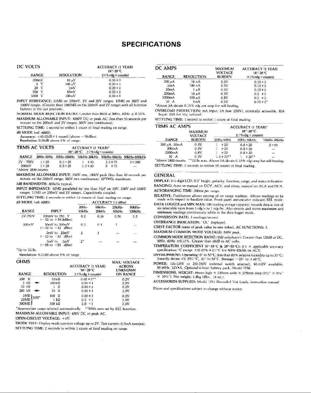
Keithley 175 User manual

-~
ARTISAN
®
~I
TECHNOLOGY
GROUP
Your definitive source
for
quality
pre-owned
equipment.
Artisan Technology
Group
Full-service,
independent
repair
center
with
experienced
engineers
and
technicians
on staff.
We
buy
your
excess,
underutilized,
and
idle
equipment
along
with
credit
for
buybacks
and
trade-ins
.
Custom
engineering
so
your
equipment
works
exactly as
you
specify.
•
Critical
and
expedited
services
•
Leasing
/
Rentals/
Demos
• In
stock/
Ready-to-ship
•
!TAR-certified
secure
asset
solutions
Expert
team
ITrust
guarantee
I
100%
satisfaction
All
tr
ademarks,
br
a
nd
names, a
nd
br
a
nd
s a
pp
earing here
in
are
th
e property of
th
e
ir
r
es
pecti
ve
ow
ner
s.
Visit our website - Click HERE

SPECIFICATIONS

TABLE OF CONTENTS
Paragraph Title Peg.3
1.1
1.2
1.3
1.4
1.5
1.6
1.7
1.8
‘SECTION l-GENERAL INFORMATION
Introduction .............................
Getting Started ..........................
Unpacking and Inspection .................
Specifications ...........................
Warranty Information .....................
Manual Addenda .........................
Safety Symbols and Terms. ................
Optional Accessories. .....................
.................
.................
.................
.................
.................
.................
.................
.................
......
......
......
......
......
......
......
......
..........
..........
..........
..........
..........
..........
......
......
......
1-l
1~1
l-l
1-2
l-2
1-2
1-2
1-2
2-1
2-1
2.1
2.2
2.3
2.3.1
2.3.2
2.3.3
2.4
2.4.1
2.4.2
2.4.3
2.4.4
2.5
2.6
2.6.1
2.6.2
2.7
2.7.1
2.7.2
2.7.3
2.7.4
2.7.5
2.7.6
2.7.7
2.7.8
2.7.9
2.7.10
2.7.11
2.8
2.8.1
2.8.2
2.8.3
2.8.4
3.1
3.2
3.3
3.4
3.5
3.5.1
3.5.2
3.5.3
3.5.4
3.5.5
SECTION 2-BENCH OPERATION
Introduction ....................................
High Energy Circuit Precautions. ...................
Preparation for Use ..............................
LinePower.. .................................
Battery Pack Power. ...........................
Batten, Charging ..............................
Front Panel Familiarization ........................
Display ......................................
Front Panel Controls ...........................
Input Terminals ...............................
Current Fuse Replacement ......................
Error Messages .................................
Operating Conditions ............................
Environmental Conditions. ......................
Maximum Allowable Input ......................
Basic Bench Measurements .......................
Power-Up ....................................
Relative Mode ................................
DC Voltage Measurements. .....................
TRMS AC Voltage Measurements. ...............
Resistance Measurements ......................
Current Measurements (DC or TRMS AC) .........
AC Plus DC Measurements .....................
dl3 Measurements .............................
dl3 Measurement Considerations and Applications
MINtMAX and 100 Point Logger Operation .......
DiodeTest ...................................
TRMS Consideration .............................
AC Voltage Offset .............................
TRMS Measurements Comparison ...............
Crest Factor ..................................
Extended Frequency Response ..................
SECTION 3-PERFORMANCE VERIFICATION
Introduction ....................................
Environmental Conditions .........................
Recommended Test Equipment. ...................
Initial Conditions ................................
Verification Procedure ............................
DC Voltage Accuracy Check ....................
AC Voltage Accuracy Check ....................
Resistance Accuracy Check .....................
DC Current Accuracy Check ....................
AC Current Accuracy Check ....................
..........
..........
..........
..........
..........
..........
..........
..........
..........
..........
......
......
......
......
... ..
......
2~1
2-l
2-l
2-1
2~2
2-2
2-2
2-3
2-3
2-3
2-3
2-3
2-4
2-4
2-4
2-4
2-4
2-9
2-9
2-9
3-2
3-2
3-2
3-3

TABLE OF CONTENTS
Paragraph Title Page
4.1
4.2
4.3
4.3.1
4.3.2
4.3.3
4.3.4
4.3.5
4.3.6
4.4
4.4.1
4.4.2
4.4.3
4.4.4
4.5
4.6
4.7
5.1
5.2
5.3
5.4
5.4.1
5.4.2
5.4.3
54.4
5.4.5
5.5
5.6
5.7
5.7.1
5.7.2
5.7.3
5.7.4
5.7.5
5.7.6
5.7.7
5.7.8
6.1
6.2
6.3
6.4
6.5
SECTION 4-THEORY OF OPERATION
Introduction ..................................................................................
Overall Functional Description ...................................................................
AnalogCircuitry ...............................................................................
Multiplexer .................................................................................
InputBufferAmplifier ........................................................................
~2VRefetenceSource ........................................................................
AiDConverter ..............................................................................
Input Signal Conditioning .....................................................................
ACConverter ...............................................................................
DigitalCircuitry ...............................................................................
Microcomputer .............................................................................
AddressDecoding ...........................................................................
PIA .......................................................................................
Display Board
...............................................................................
DigitalCalibration .............................................................................
PowerSupply ................................................................................
Model17588atten/Option ......................................................................
SECTION 5-MAINTENANCE
Introduction ..................................................................................
Top Cover Removal/Installation .................................................................
Batten/ Pack (Model 1768) Installation .............................................................
Troubleshooting ..............................................................................
RecommendedTestEquipment ................................................................
SelfDiagnosticProgram ......................................................................
PowerSupplyChecks ........................................................................
AfDConverterandDisplay ...................................................................
Signalconditioning ..........................................................................
LineFuseReplacement .........................................................................
Special Handling of Static Sensitive Devices .......................................................
Front Panel Calibration .........................................................................
Recommended Calibration Equipment ..........................................................
CalibrationJumper.. ........................................................................
Environmentalconditions .....................................................................
DC Voltage Calibration
.......................................................................
ACVoltageCalibration .........................................................................
Resistance Calibration. .......................................................................
Frequencycompensation .....................................................................
CalibrationStorage ............................................................................
SECTION 6-REPLACEABLE PARTS
Introduction ..................................................................................
ReplaceableParts .............................................................................
Orderinginformation ...........................................................................
FactoryService.. .............................................................................
Component Location Drawings and Schematic Diagrams ...........................................
4-l
4-1
4-l
4-2
4-2
4-2
4-2
4-3
4-4
45
4-5
4-5
4-5
4-5
4-5
4-5
4-5
5-1
5-l
5-l
5-l
5-l
5-2
5-4
5-4
5-4
5-6
5-6
5-7
5-7
5-7
5-7
5-7
5-8
5-8
59
6-l
6-l
6-l
6-l
6-l

LIST OF ILLUSTRATIONS
Figure
2-1
2-2
2-3
2-4
2-5
2-6
2-7
4-1
4-2
4-3
4-4
4-5
4-6
5-l
5-2
6-l
6-2
6-3
6-4
6-5
6-6
6-7
6-8
Title
Model175FrontPanel ..................................................
DC Voltage Measurements. ..............................................
TAMS AC Voltage Measurements. ........................................
Resistance Measurements ...............................................
Current Measurements Between 2000mA and 20A. ..........................
Current Measurements up to 2000mA .....................................
Model 175 Typical AC Frequency Response ................................
Simplified Block Diagram ................................................
Simplified Schematic of the Multiplexer ....................................
Simplified Schematic of the Input Buffer Amplifier ...........................
AIDConverter .........................................................
Resistance Measurements Ratiometric Technique. ...........................
Simplified Schematics of Ohms Circuitry ...................................
Segment Identification ..................................................
CalibrationJumper.. ...................................................
Modell75ExplodedView ................................................
Model 175 Display Assembly .............................................
Display Board, Component Location Drawing, Dwg. No. 175-110. ..............
Model 1758 Battery Pack, Component Location Drawing, Dwg. No. 1755.100 ....
Mother Board, Component Location Drawing, Dwg. No. 175-100 ..............
Mother Board, Schematic Diagram, Dwg. No. 175.106 .......................
Display Board, Schematic Diagram, Dwg. No. 175.116 .......................
Model 1758 Battery Pack, schematic Diagram, Dwg. No. 1758-106 .............
Page
2-2
2-5
2-5
2-6
2-6
2-6
2.11
4-l
4-2
4-2
4-3
4-4
4-4
5-2
5-9
6-2
6-3
6-9
811
6-13
6-17
6-21
6-23
iii

Table
2-l
2-2
2-3
2-4
2-5
2-6
3-l
3-2
3-3
3-4
3-5
5-l
5-2
5-3
5-4
5-5
5-6
5-7
5-8
5-9
5-10
6-l
6-2
6-3
6-4
LIST OF TABLES
Title
ErrorMessages .....................................
Model 175 Maximum Allowable Inputs ..................
dB Specifications for DC Volts (6OOL1Refl ...............
d8 Specifications for AC Volts (6OOfl Refl ...............
Levels for Other Reference Impedances .................
Comparison of Average and TRMS Meter Readings .......
Equipment Specifications.
............................
Limits for DC Voltage Verification ......................
Limits for AC Voltage Verification ......................
Limits for Resistance Verification .......................
Limits for DC Current Verification ......................
Recommended Troubleshooting Equipment. .............
Troubleshooting Modes ..............................
Power Supply Checks. ...............................
A/D Converter Checks ...............................
Display Board Checks.. ..............................
Static Sensitive Devices ..............................
Recommended Calibration Equipment ..................
DC Voltage Calibration ...............................
AC Voltage Calibration ...............................
Resistance Calibration. ...............................
MotherBoard,PartsList ..............................
Display Board, Parts List. .............................
Model 1758 Battery Pack, Parts List ....................
Model 1758 Spare Pats List. ..........................
......
......
......
......
......
......
......
......
......
......
......
......
......
......
......
......
......
......
......
......
......
......
......
......
......
......
......
......
......
......
......
......
......
......
......
......
......
......
......
......
......
......
......
......
......
......
......
......
......
......
......
......
......
......
......
......
......
......
......
......
......
......
......
......
......
......
......
......
......
......
......
......
......
......
......
......
......
......
......
......
......
......
......
......
......
......
......
......
......
......
......
......
......
......
......
......
......
......
......
......
......
......
......
......
......
......
......
......
......
......
......
......
......
......
......
......
......
......
......
......
......
......
Page
iv

SAFETY PRECAUTIONS
The following safety precautions should be observed before operating
the Model 175.
This instrument is intended for use by qualified personnel who
recognize shock hazards and are familiar with the safety precautions re-
quired to avoid possible injury. Read over the manual carefully before
operating this instrument.
Exercise extreme caution when a shock hazard is present at the instru-
ment’s input. The American National Standards Institute (ANSI) states
that a shock hazard exists when voltage levels greater than 30V rms or
42.4V peak are present. A good safety practice is to expect that a
hazardous voltage is present in any unknown circuit before measuring.
Inspect the test leads for possible wear, cracks or breaks before each
use. If any defects are found, replace with test leads that have the same
measure of safety as those supplied with the instrument.
For optimum safety do not touch the test leads or the instrument while
power is applied to the circuit under test. Turn the power off and
discharge all capacitors, before connecting or disconnecting the instru-
ment.
Do not touch any object which could provide a current path to the
common side of the circuit under test or power line (earth) ground.
Always make measurements with dry hands while standing on a dry,
insulated surface, capable of withstanding the voltage being measured.
Exercise extreme safety when testing high energy power circuits (AC
line or mains, etc.). Refer to the operation section.
Do not exceed the instrument’s maximum allowable input as defined in
the specifications and operation section.

MODEL 175 AUTORANGING DMM
Features:
04% Digit LCD Display
*Fast Autoranging
*Bench or Portable
*Digital Calibration
l
lOO Point Data Logger
l
10~V/10mW10nA Sensitivity
~0.03% Basic DCV Accuracy
l
TRMS AC
l
dBm/Relative Functions
l
Min/Max Reading Hold
*Safety Input Jacks
*lOA Capability
l
lOOkHz Specified AC Bandwidth
Options:
*Model 1758 Rechargeable Battery Pack
*Model 1753 IEEE-488 Interface

SECTION 1
GENERAL INFORMATION
1.1 INTRODUCTION
This instruction manual contains the necessary information
for operating and maintaining the Model 175 Autoranging
Multimeter and the Model 1758 Rechargeable Battery Pack.
The information is divided into the following sections:
Section 1 contains general information and provides
guidelines for using this manual. Important safety infor-
mation is also presented here.
Section 2 contains detailed bench operation information
for the Model 175.
Section 3 contains the information needed to verify the
accuracy of the Model 175. Performance verification can
be done upon receipt of the unit or whenever the basic
accuracy is in question.
For the more technically oriented, information on theory
of operation, and maintenance and servicing is contained
in Section 4 through 6.
NOTE
The Model 1753 IEEE-488 interface comes sup-
plied with its own instruction manual.
1.2 GE-iTING STARTED
Perform the following steps in sequence to acquaint yourself
auicklv and safelv with the basic operation of the Model 175.
Verify that the Model 175 was not damaged in transit, es
explained in paragraph 1.3.
Carefully read the safety precautions and warnings found
preceding this section and the first two sections (General
Information and Bench Operation) of this manual.
Referring to paragraph 2.3.1 (Line Power) set the line
voltage switch and plug the power cord into a properly
grounded outlet. If the optional battery pack is installed
the charge circuitry will be activated.
Acquaint yourself with the controls and display of the
Model 175 as follows:
A. Turn on the Model 175 by pressing in the ON/OFF
pushbutton. All of the zeroee will be displayed briefly.
B. Connect the supplied test leads to the
VOLTS/OHMS/mA and COM input jacks, and short
them together.
C. Select AC volts and autoranging by pressing in the
AC/DC, V and AUTO pushbuttons. The AC, mV and
AUTO annunciators will be displayed. Pressing any of
the other range pushbuttons will put the Model 175 in
manual ranging es indicated by the absence of the
AUTO annunciator.
D.
E.
F.
G.
H.
I.
Select DC volts by releasing (outi the AC DC
pushbutton (V still selected]. The AC annunciator will
turn off.
Select autoranging ohms by pressing in the !!
pushbutton (DC still selected) and AUTO pushbutton.
The n annunciator will turn on. Press the AC:DC
pushbutton in (AC selected) and note the “Err”
message indicating that this is an invalid mode.
Select AC or DC current by setting the AC DC
pushbutton accordingly and pressing I,? ihe A
pushbutton. The annunciator that reflects the selected
range will turn on. Note that current will not autorange
and that the 10 AMPS and COM input jacks must be
used on the 10A range.
Select
dB by placing the Model 175 in AC or DC volts
and pressing the dB pushbutton. The dB annunc~etor
will turn on. Press the dB button again fo take the
Model 175 out of the dB measurement mode.
REL (relative) can be used with any measurement furw
tion: volts, ohms, amps or dB. For example, place the
Model 175 in ohms and autorange. The display wll
read approximately 00.141!, which is the test lead
resistance. Press the REL pushbutton. The REL any
nunciator will turn on and the display will now reed
OO.OOI2.The relative level of 0.1411 will be subtracted
from all subsequent ohm measurements. Press the
REL pushbutton a second time to cancel the REL
level.
To activate the 100 point DATA LOGGER with
MIN/MAX, press and hold in the STOiCLR pushbut-
ton. When the reading rate A = 0 is displayed let go of
the button, The ST0 annunciator will turn on Press
the RCL pushbutton and the last data point will be
displayed briefly followed by the reading (data]. Other
data points can be displayed by holding in the RCL but-
ton. Turn off the DATA LOGGER by pressing the
STOlCLR pushbutton again.
5. When you are comfortable with the controls of the Model
175, go on and make the desired meaeurements using
Section 2, Bench Operation es a guide.
1.3 UNPACKING AND INSPECTION
The Model 175 Bench DMM was carefully inspected, both
mechanically and electrically, before shipment. Upon recelv
ing the Model 175, carefully unpack all items from the ship-
ping carton and check for any obvious signs of physical
damage that might have occurred during shipment. Report
the damage to the shipping agent immediately. Retain the
1-l

original packing materials in case reshipment becomes
necessan/. The following items are included with every Model
175 order:
*Model 175 Autoranging Multimete!
*Model 175 instruction Manual
‘Model 1751 Safety Test Lead
*Additional accessories as ordered.
1.4 SPECIFICATIONS
Detailed Model 175 specifications may be found immediately
preceding the table of contents of this manual.
1.5 WARRANTY INFORMATION
Warranty information may be found on the inside back cover
of this manual. Should it be necessary to exercise thewarran-
ty, contact your Keithley representative or the factory to
determine the correct course of action. Keithley Instruments
maintains service facilities in the United States, West
Germany, Great Britain, France, the Netherlands.
Switzerland and Austria. Information concerning the applica-
tion, operation or service of your instrument may be directed
to the applications engineer at any of theses locations. Check
the inside front cover of this manual for addresses.
1.6 MANUAL ADDENDA
Information concerning improvements or changes to the in-
strument which occur after the printing of this manual will be
found on an addendum sheet included with this manual. Be
sure to review these changes before attempting to operate or
service the instrument.
1.7 SAFETY SYMBOLS AND TERMS
The following safety symbols and terms are used in this
manual or found on the Model 175.
The symbol ! on the instrument indicates that the user
The symbol ,$
should refer to the operating instructions in this manual.
on the w,trument indicates that a potential
of 1OOOV or more may be present on the terminal(s). Stan-
dard safety practices should be observed when such
dangerous voltages are encountered.
The WARNING heading in this manual explains dangers that
could result in personal injury or death.
Model 1017 Dual Rack Mounting Kit-Use to mount two
Model 175’s in a standard 5 x X 19” rack.
Model 1301 Temperature Probe-A rugged low cost
temperature probe designed to allow precision temperature
measurements from -55OC to 150°C.
Range: -55’C to 150°C
Output: lmV/OC; compatible with any DMM with at least
IOM12 input impedance.
Accuracy: f2OC from O” to 100°C; *YC from -5Y to
0°C and 100’ to 150°C
Power: 9V alkaline or C-Zn (NEDA 1604) battery.
Model 1600A High Voltage Probe-Extends the DMM to
40kV.
Maximum Input: 40kV DC or peak AC to 300Hr
Input Resistance:lOOOM12
Division Ratio: 1OOO:l
Ratio Accuracy: f2.5% from 1kV to 40kV DC, *3.5% if
200mV or 2V ranges of Model 175 are used; -3dB at 300Hz
AC
Operating Temperature: 0’ to 50°C
Model 1651 50.Ampere Current Shunt-The external
O.OOlI2 f I%, a-terminal shunt permits current
measurements from O-50A DC or AC.
Model 1681 Clip-On Test Lead Set-contains two leads,
1.2m (48 inches) long terminated with banana plugs and
spring action clip on probes.
Model 16ElZA RF Probe-Permits voltage measurements
from 1OOkHz to 250MHr.
AC to DC transfer accuracy: *ldB from 1OOkHz to
250MHr at IV, peak responding, calibrated in rms of a sine
wave.
Maximum Allowable Input: 42V AC peak, 200V IDC + AC
peak)
Model 1684 Hard Shell Carrying Case-Hard vinyl case,
1OOmm x 300mm x 350mm 14 x I3 x I4 inches1 has a fit-
ted foam insert with room for the Model 175, instruction
manual and small accessories.
Model 1685 Clamp-On AC Probe-Measures AC current
by clamping onto a single conductor. Interruption of the cir-
cuit under test is unnecessary. The Model 1685 detects cur-
rent by sensing the changing magnetic field produced by the
current flow.
Range: 2, 20 and 200A rms
Accuracy: 54% of range at 60Hz; + 6% of range at 50Hz
Temperature Coefficient: +0.05%/°C on 20A and 200A
range; k0.3%/°C on 2A range
Maximum Allowable Current: 300A rms
Maximum Conductor Voltage: 6OOV rms
Conversion Ratio: O.lV/A rms
The CAUTION heading in this manual explains hazards that Model 1751 Safety Test Leads-This is the test lead set
could damage the instrument. supplied with each Model 175. Finger guards and shrouded
banana plugs help minimize the chance of making contact
1.8 OPTIONAL ACCESSORIES with live circuitry.
The following accessories can be used with the Model 175. Model 1753 IEEE-488 Interface-Field installable program-
mable option provides isolated data output. Switch-
Model 1010 Single Rack Mounting Kit-Use to mount selectable talk onlyoraddressable modes. Mounts within and
one Model 175 in a standard 5 x X 19” rack. powered by the Model 175.
l-2

Model 1754 Universal Test Lead Kit-12 piece test lead kit, minimum operation from full charge, recharges within 10 hours
with interchangeable plug-in accessories. Kit includes: one set and is field installable.
of test leads (i-red. l-black), two spade lugs, two standard ba-
nana plugs, two phone tips (.060DIA.), two hooks and two mini- Model 7008 IEEE-488 Digltal Cabl+Useful for connecting
the Model 1753 to the IEEE-488 bus. The Model 7008-3 is 0.9m
ature alligator clips (with boots).
Model 1758 Rechargeable Battery Pack-Provides six hours (3ft) in length and has a standard IEEE-488 connector at each
end. The Model 7008-6 is 1.8m (6ft) in length.
l-311-4


SECTION 2
BENCH OPERATION
2.1 INTRODUCTION
This section contains the information needed to prepare and
operate the Model 175 as a bench DMM. Bench operation
consists of using the Modal 175 to perform basic voltage,
currant, resistance and dB measurements. Also, the opera-
tion of the data logger is covered hare. The capabilities of the
Model 175 can be enhanced with the addition of the Model
1753 IEEE-488 interface. IEEE operation is covered in the
Modal 1753 Instruction Manual.
2.2 HIGH ENERGY CIRCUIT PRECAUTIONS
To optimize safety when measuring voltage in high energy
distribution circuits, read and use the directions in the follow-
ing warning.
WARNING
Dangerous arcs of an explosive nature in a high
energy circuit can cause sevare personal injury
or death. If the mater is connected to a high
energy circuit when set to a currant range, low
resistance range or any other low impedance
range, the circuit is virtually shorted. Dangerous
arcing can result awn when the mater is sat to a
voltage range if the minimum safety spacing is
reduced.
When making measurements in high energy circuits use test
leads that meat the following requirements:
1. Test leads should be fully insulated.
2. Only use test leads that can be connected to the circuit
leg. alligator or spade plugs) for hands-off measurement.
3. Do not use test leads that decrease voltage spacing. This
diminishes arc protection and creates a hazardous condi-
tion.
Use the following sequence when testing power circuits:
1. De-energize the circuit using the regular installed connact-
disconnect device such as the circuit breaker, main switch,
etc.
2. Attach the test leads to the circuit under test. Use ap-
propriate safety rated leads for this application.
3. Sat the DMM to the proper function and range.
4. Energize the circuit using the installed connect-disconnect
device and make measurements without disconnecting the
DMM.
5. De-energize the circuit using the installed connect-
disconnect device.
6. Disconnect the test leads from the circuit under test.
2.3 PREPARATION FOR USE
2.3.1 Line Power
The Model 175 is provided with a three-wire line cord which
mates with third-wire grounded receptacles. Connect the ins
strumant to AC line power as follows:
1. Sat the LINE VOLTAGE switch on the back of the instru-
ment to correspond to line voltage available. Ranges are
105.12511 or 210.250V 50/60Hz AC.
CAUTION
Connect only to the line voltage selected.
Application of incorrect voltage can
damage the instrument.
2. Plug the power cord into a properly grounded outlet.
WARNING
Ground the instrument through a properly
grounded receptacle before operation.
Failure to ground the instrument can result
in savere injury or death in the avent of
short circuit or malfunction.
NOTE
Although the Model 175 is specified at 50 and
60Hz the instrument may be operated at 400Hz
and 440Hz. Add ona. count to instrument
specifications under this condition.
2.3.2 Battev Pack Power
The Modal 175 may also be operated from rechargeable
sealed nickel-cadmium batteries contained in the optional
Model 1758 Rechargeable Batwry Pack. The battery pack will
operate the Modal 175 for up to six hours The BAT annun-
ciator will turn on when the battery charge is insufficient to
maintain accurate readings. Refer to Section 5, paragraph 5.3
for installation procedures.
2.3.3 Battery Charging
After the Model 1758 Battery Pack is installed in the Model
175 it can be charged and recharged as follows:
1. Connect the instrument to line power as described in
paragraph 2.3.1.
2. With the power switch off, the battery charge circuitry is
automatically energized to charge the battery at the maxi-
mum rata. When the battery pack is first installed, or if it is
completely discharged, allow it to charge for ten hours.
2-1

NOTE
For maximum battery efficiency only charge the
battery pack after it has become discharged and
only charge until it is fully charged (=,lOhours).
Continuous charging over long periods of time
will not damage the batteries but, usefu life will
gradually decrease. This loss is not permanent
and may be restored by cycling the battery pack
through several complete charge/discharge
cycles. The battery pack is capable of 500 to
1000 charge/discharge cycles before replace-
ment is needed.
Do not make measurements with the BAT an-
nunciator on as the readings may be erroneous.
3. When the Model 175 is in use on line power, the battery
charger maintains a trickle charge on the battery pack.
2.4 FRONT PANEL FAMILIARIZATION
The following paragraphs and Figure 2-l provide a brief
description of the display, front panel controls and input ter-
minals.
2.4.1 Display
The Model 175 has a 4 % digit liquid crystal display (LCD).
The minus sign is displayed. The plus sign is implied by the
absence of the minus sign. The following annunciators are
displayed on the LCD.
BAT-Low battery indicator for the Model 1758.
AC-AC selected (DC implied by absence of AC annun-
ciator).
mV or V-Millivolts or volts selected.
n, kR or Mn-Ohms, kilohms or megohms selected.
p, mA or A-Microamps, milliamps or amps selected.
RMT (Remote)-Model 175 being controlled over the
IEEE-488 bus (Model 1753 installed).
C-Model 175 in calibration mode.
AUTO-Autorange selected.
REL--Relative selected.
dB-Decibel selected.
STO-Data being stored.
RCL-Data being recalled. RCL flashes when buffer is full
during logging cycle.
2.4.2 Front Panel Controls
ON/OFF-Pressing in this pushbutton turns the Model 175
on. Releasing (out) this pushbutton turns the instrument off.
REL (Relative)-This pushbutton allows readings to be
made with respect to any baseline value. Also allows zeroing
of on range readings. See paragraph 2.7.2 for more detailed
information on REL.
dB-This pushbutton selects the dB function and is used
along with the ACV or DCV function. Measurements are
made in dBm referenced to 600% REL can be used to make
any voltage level the OdB reference point for dB
measurements.
DATA LOGGER-Has min/max and 100 point reading
storage capacity; records data at one of six selectable rates
from every reading to 1 rdglhr. Records maximum and
minimum conversion during the period the data logger is ac-
tive at the rate of 3lsec.
1. STO/CLR-Pressing this button initiates the logging se-
quence. Pressing the button a second time shuts off the
data logger.
2. RCL-Pressing and holding this button in scrolls the data
pointer. To read the data at a particular point, simply
release the button.
AC/DC-This switch is used along with the volts (V), cur-
rent (A), and dB functions. Depressing (in) this pushbutton
selects AC and releasing (out) this pushbutton selects DC.
V-Depressing this pushbutton selects the volts function.
O-Depressing this pushbutton selects the ohms function.
The AC/DC pushbutton must be released (out).
A-Depressing this pushbutton selects the current function.
Range Push Buttons
1. AUTO-Depressing this pushbutton causes volts and
ohms to autorange. In current, it selects the 10A range (no
autoranging in current).
%iEiq
175 AUTORANGING MVLTIMETER I
Figure 2-l. Model 175 Front Panel
2-2

2. Manual ranging is accomplished by depressing the ap
propriate range button.
2.4.3 Input Terminals
The input terminals are intended to be used with safety
shrouded test leads to help minimize the possibility of contact
with live circuits. Safety shrouded test leads are supplied with
the Model 175.
VOLTS/OHMS/mA and COM (Red and Black)-Use this
pair of terminals for all volt, ohm, milliamp and dB
measurements.
10 AMPS and COM (White and Black)-Use this pair ex-
clusively for measuring currant up to 10A (up to 20A for 15
seconds,.
2.4.4 Current Fuse Replacement
The current fuse protects the 200pA through 2000mA ranges
from an input currant greater than 2A. To replace the current
fuse, perform the following steps:
1. Turn off the power and disconnect the power line and test
leads.
2. Place the end of a flat-blade screwdriver into the slot in the
fuse holder on the front panel. Press in slightly and rotate
the fuse carrier one-quarter turn counterclockwise.
Release pressure and remove the fuse carrier and the fuse.
3. Remove the defective fuse and replace it with the follow-
ing type: ?A, 250V. 3AG. normal-blow Keithley part
number FU-13, or equivalent.
CAUTION
Use only the recommended fuse type. If a fuse
with a higher current rating is installed, instru-
ment damage may occur.
2.5 ERROR MESSAGES
Table 2-l lists the error messages associated with basic front
panel operation. Note that the instrument has a number of
other massages that are discussed in the appropriate sections
of this manual.
2.6 OPERATING CONDITIONS
2.6.1 Environmental Conditions
All measurements should be made at an ambient temperature
within the range of OOCto 5OOC. and with a relative humidity
of 0% to 80% up to 35OC. For instruments above 35OC
derate humidity 3% per OC up to 50°C. If the instrument has
been subjected to extremes of temperature, allow sufficient
time for internal temperatures to reach environmental condi-
tions. Typically, it takes one hour to stabilize a unit that is
10°C (18OF, out of specified temperature range.
Table 2-1. Error Messages
Comments
Model 175 locks up. See Section 5 for troubleshooting information.
Model 175 locks up, but operation can be restored by pressing
any one of the four momentary pushbuttons. If restored,
calibration is invalid as indicated by the flashing “C” annunciator.
See Section 5 for troubleshooting information.
Overrange input applied to the Model 175. Leading minus sign
indicates that input signal has a negative value.
“AC” and “R” annunciators flash. Correct problem by releasing
(out, AC/DC pushbutton.
Table 2-2. Model 175 Maximum Allowable Inputs
Ranges -
200mV. 2V
20-1ooov
200mV
2.750V
200w-2000mA
10A
All
Maximum Allowable Inputs
1OOOVDC or peak AC for less than 10s~ par minute.
300Vrms continuous.
1OOOVDC or peak AC.
750Vrms 1OOOV peak for lass than 1Osec per minute.
300Vrms continuous. lO’V*Hz maximum.
750Vrms. 1OOOV peak. 107V*Hz maximum.
2A, 250VDC or rms (fuse protected).
10A continuous; 20A for lbec (unfused,.
450VDC or peak AC
2-3

2.6.2 Maximum Allowable Inputs
Table 2-2 lists the maximum allowable inputs for the Model
175.
2.7 BASIC BENCH MEASUREMENTS
Basic measurement techniques for using the Model 175 to
measure AC and DC volts, resistance, AC and DC current
and dB are covered in the following paragraphs. Also in-
cluded is the operation of the MIN/MAX and 100 point data
logger.
WARNING
Before operating the Model 175, observe
the safety precautions found preceding
Section 1. When testing high energy power
circuits follow the procedure found in
paragraph 2.2 High Energy Circuit Precau-
tions. Failure to observe these and other
safety precautions found in this manual
could result in severe injury or death.
The COM terminal on the Model 175 is designed to float
above earth ground to avoid ground loop problems.
WARNING
Hazardous voltages may be applied to the
COM terminal. The maximum allowable
voltage between the COM terminal and
chassis ground is 500V. Destruction of in-
sulation, which could present a shock
hazard, may occur if the 500V maximum is
exceeded.
CAUTION
Do not exceed the maximum input limits
shown in Table 2-2.
2.7.1 Power-Up
NOTE
The software revision level of the Model 175 can
be displayed upon power-up by running the
diagnostic program. See Section 5,
Maintenance, for more information.
Turn on the Model 175 by pressing in the ON/OFF switch.
The following will occur:
1. Reset-All zeros will be briefly displayed before going into
the measurement mode.
2. RAM Test-If this test fails the Model 175 will lock up with
zeros displayed.
3. NVRAM Test-If this test fails the display will show the error
message “cErr”
Refer to Table 2-l for mc~re information pertaining to error
messages.
2.7.2 Relative Mode
When the relative mode is selected with an on-scale reading
on the display the following occurs:
1. The REL annunciator is displayed.
2. The next reading is stored.
3. The stored reading is then algebraically subtracted from all
subsequent readings and displayed.
A REL level can be established for any measurement function
(Volts, Ohms, Amps and dB1 and is effective only on that
function. Changing functions will not affect a REL level
already established. However, if another REL level is set (on
any function) the previous REL level will be cancelled. For ex-
ample, place the 175 in the R function and select the 2OOn
range. Short the test leads and press the REL button. Note
that the REL annunciator is on. Select DCV and note that the
REL annunciator is off, indicating that there is not a REL level
established for DCV. Switch back to 0 and note that the REL
level is still there. Again, go to DCV and set a REL level of
+ IV. The REL annunicator will go on. Switch back to n and
note that the REL annunciator is off, indicating that the REL
level for 0 is cancelled.
Once a REL level is established for a measurement function,
that stored level will be the same regardless of what range the
Model 175 is on. For example, if + IV is established as the
REL level on the 20VDC range, + IV will also be the REL level
on the 1OOOVDC range.
It is important to note that the use of REL reduces the
dynamic range of measurements by that level. For instance,
assume that the REL level is +lV and the Model 175 is
manually set to the 2V range. The maximum positive
displayed reading, before overranging, would be +0.9999\1.
This is because the A/D converter would be seeing 1.9999V
(maximum) from the input. Thus, the dynamic range of
measurement is -1.9999V to + 0.9999V (2.999BV) as com-
pared to the normal -1.9999V to + 1.9999V (3.9998V). The
dynamic range of measurement has been reduced by IV. The
effects on dynamic range can be reduced by selecting a
higher range or using autorange.
2.7.3 DC Voltage Measurements
The Model 175 can make DC voltage measurements between
1OhV and IOOOV. The basic procedure is as follows:
I. Connect the test leads to the VOLTS and COM terminals
of the Model 175.
2. Select the DCV function.
3. Select a range consistent with the expected voltage. For
automatic range selection, press in the AUTO pushbutton.
NOTE
Manual ranging is recommended for routine
measurements above 200V.
2-4

4. Connect the test leads to the source as shown in Figure
2-2. If the positive source terminal is connected to the
COM terminal of the instrument, the display will show a
negative value. If the negative source terminal is con-
nected to the COM terminal, the display will show a
positive value.
5. Observe the display; if the “OL” message is shown, select
a higher range until a normal reading is shown. Always use
the lowest possible range for the best resolution.
6. Take the reading from the display.
NOTE
High input impedance j VlOOOMRl DC volts
measurements can be made on the 200mV and
2V ranges by releasing (out) all the function
pushbunons (AC/DC, V, R, A).
DC
VOLTAGE
SOURCE
Figure 2-2. DC Voltage Measurements
2.7.4 TRMS AC Voltage Measurements
The Model 175 can make TRMS AC voltage measurements
between IOwV and 75OV. Proceed as follows:
1. Connect the test leads to the VOLTS and COM terminals
of the Model 175.
2. Select the ACV function.
3. Select a range consistent with the expected voltage. For
automatic range selection, press in the AUTO pushbutton.
NOTE
Manual ranging is recommended for routine
measurements above 200V.
4. Connect the test leads to the source as shown in Figure
2.3.
5. Observe the display; if the “OL” message is shown, select
a higher range until a normal reading is shown. Always use
the lowest possible range for the best resolution.
6. Take the reading from the display.
NOTE
See paragraph 2.8 for TRMS considerations.
AC
VOLTAGE
Figure 2.3. TRMS AC Voltage Measurements
2.7.5 Resistance Measurements
The Model 175 can make resistance measurements between
1OmfI and 200MQ The 2MIf. 20MR and 200M12 ranges will
autorange when the MI1 pushbutton is pressed in. Proceed as
follows to make resistance measurements:
1. Connect the test leads to the OHMS and COM terminals of
the Model 175.
2. Select the II function.
NOTE
The message “Err” and flashing II and AC an-
nunciators will be displayed if the AC/DC push-
button is pressed in. This is an invalid mode. To
correct, simply release (out) the AC/DC pushy
button.
3. Select a range consistent with the expected resistance. For
automatic range selection. use the autorange mode.
NOTE
Zeroing may be necessary to compensate for
test lead resistance on the 20011 and 2kR ranqos.
Zero the display as follows:
A. Short the to?., leads together.
B, Press the REL pushbutton. The display will zero.
C. Proceed to step 4.
4. Connect the test leads to the resistance to be measured as
shown in Figure 2-4.
5. Observe the display: if the “OL” message reading is
shown, select a higher range until a normal reading is
shown. Always use the lowest possible range for the best
resolution.
6. Take the reading from the display
NOTE
It is helpful to shield resistances greater than
106R (1MR) if a stable reading is expected. Place
the resistance in a shielded enclosure and elect
trically connect the shield to COM of the Model
175
2-5

Figure 2-4. Resistance Measurements
2.7.6 Current Measurements (DC or TRMS AC)
The Model 175 can make DC or TRMS AC current
measurements between lO@A and IOA (20A for 15 seconds).
If the expected current level is in question, make the initial
measurement with the 10A range. This will help prevent the
inadvertent blowing of the 2A current fuse.
NOTE
For routine measurements above 10A it is
recommended that the Model 1651, 50.Ampere
current shunt be used.
1. For current measurements between 2000mA and 20A.
A. Connect the test loads to the 10 AMPS and COM ter-
minals of the Model 175.
NOTE
The test leads used must be capable of handling
20A and it is recommended that thev be twisted
(see Figure 2-5) to minimize external iields which
could affect the Model 175 or other equipment.
Also, keep the test leads es short as possible to
minimize voltage drop.
B. Select the ACA or DCA function.
C. Select the 10A range. Current does not autorange.
D. Connect the test leads to the current source as shown
in Figure 2-5 and make the reading from the display.
NOTE
Up to 5A may be applied continuously without
degradation of the measurement due to self-
hosting effects. Above 5A derate 0.15% rdg per
amp for self-heating. For currents between IOA
and 20A. specified accuracy can only be ob-
tained when measurements are limited to a max-
imum of 15 seconds.
2. For current measurements up to 2000mA:
A. Connect the test leads to the mA and COM terminals of
the Model 175.
B. Select the ACA or DCA function.
C. Select an appropriate range for the expected current.
Current measurements cannot autorange.
D. Connect the test leads to the current source as shown
in Figure 2-6. If an overrange indication is displayed
select a higher range until a normal reading is shown.
Use the lowest possible range for the best accuracy.
E. Make the reading from the display.
CURRENT
TWISTED SOURCE
Figure 2-5. Current Measurements Between 2000mA
and 20A
CURRENT
SOURCE
Figure 2-6. Current Measurements up to 2000mA
2.7.7 AC Plus DC Measurements
Use the Model 175 to measure TRMS on a signal which has
both AC and DC components as follows:
1. Measure and record the TRMS AC component as de-
scribed in paragraph 2.7.4.
2. Measure and record the DC component as described in
paragraph 2.7.3.
3. Compute the rms value from the following equation:
E
-\/E
RMS - DC
2 + E,,?
2.7.8 dB Measurements
The dB function makes it possible to compress a large range
of readings into a much smaller scope. The relationship be-
tween dB and voltage can be expressed by the following
equation. VW,
dB = 20 log __
VFW
2-6

Tables 2-3 and 2-4 list the dB specifications for DC volts and To make dBm measurements referenced to 60012, pro-
AC volts. ceed es follows:
A. Connect the test leads to the VOLTS and COM tern
The Model 175 can make dBm measurements referenced to
the standard 6OOn impedance or to other impedances. The
relative feature allows measurements in dB independent of
impedance.
minals of the Model 175.
8. Select the ACV or DCV function.
C. Select autorange for optimum resolution.
D. Press the dB button.
The basic procedure for placing the instrument in the dB
mode is to first select AC or DC volts and then press the dB
button. Note that once dB is selected (dB annunciator on),
pressing in the 0 or A function pushbuttons will turn dB off.
1. dBm Measurements with 600R Reference Impedance
dBm is defined as decibels above or below a 1mW
reference. The standard reference impedance of the
Model 175 is 600% What that means is that the Model 175
is designed to read OdBm when the calculated voltage
needed to dissipate 1mW through a 600R impedance is
applied to the Model 175. That calculated voltage level is
0.7746V as derived from the basic power equation.
E=\lP.R
E = IlO-3W.6000
E = 0.7746V
E. Connect the test leads to the voltage source.
F. Make the dBm reading from the display.
2. dBm Measurements with Other Reference Impedances
dBm measurements can be made with other reference imp
pedances. The most convenient method for using other
reference impedances is to algebraically subtract the
calculated dB offset for the desired reference impedance
from the reading on the display of the Model 175. Table
2-5 lists common reference impedances and the cork
responding offset values. The following equation can be
used to calculate the offset for impedances not listed in
Table 2-5: New ref I
Offset (foi dBml : 10 log -$,o;j
Thus with a 600R reference impedance the Model 175 will
read OdBm whenever 0.7746V is applied.
NOTE
Do not confuse reference impedance with input
impedance. The input impedance of the instru-
ment is still 1OMR (see specifications) in the dB
mode.
To make dBm measutements referenced to another em-
pedance, proceed as follows:
A. Choose the desired reference impedance.
B. Calculate or look up the offset value in Table 2-5 for the
desired reference impedance.
C. Determine dBm at the desired reference impedance as
follows:
dBm (at ref 2) = 175 reading offset
Examole: Make dBm meawrements references to a
lOOI deference impedance
Table 2-3. dB Specifications for DC Volts 16OOI1Refl.
Table 2-4. dB Specifications for AC Volts l600R Refl
!
dS Mode lref: 60001
Range / Input
200mV I 1mV to 2mV
I i-58 to -52dBm)
~(Ei,2v.750v
*Up to 1ktiz
-
i?
Accuracy (* dSm)
OHz- 1
IkHz
2*
2
0.2
0.2 ~
i
IOkHz- / ZOkHz-
2OkHz 1 50kHz
- ! -
3
0.3 1
I0.26 0.56
50kHz-
1OOkHz
-
-
1.2
2-7
Table of contents
Other Keithley Multimeter manuals

Keithley
Keithley 169 User manual

Keithley
Keithley 2010 User manual

Keithley
Keithley 178 User manual

Keithley
Keithley 171 User manual

Keithley
Keithley 195A User manual

Keithley
Keithley DAQ6510 User manual

Keithley
Keithley PCIP-DMM/A User manual

Keithley
Keithley 619 User manual

Keithley
Keithley 2000 Operating instructions

Keithley
Keithley 195A User manual

Keithley
Keithley 172A User manual

Keithley
Keithley 2701 User manual

Keithley
Keithley 2700 User manual

Keithley
Keithley 164 User manual

Keithley
Keithley 3700A Series Instruction Manual

Keithley
Keithley 165 User manual

Keithley
Keithley 2100 User manual

Keithley
Keithley 2700 User manual

Keithley
Keithley 197 User manual

Keithley
Keithley DMM6500 User manual