kelda 95001000 User manual


Table of Contents
We at Kelda Showers are the inventors ofAir-Powered technology. Our patented technology delivers showers which provide
an elegant experience whilst using low amounts of water. Kelda showers are not only eco-friendly, but they are engineered
to last, too. They have been exposed and tested in the most demanding real-life environments to ensure they can withstand
the pressures of high usage.
injecting magic into the showering experience to transform the everyday bathroom into a place of personal sanctuary and
luxurious shower feel that revitalises the skin and rinses away stress.
3 - Important Safety Information
4 - System Diagram
8 - Contents
10 - Installation
22 - Maintenance
26 - Troubleshooting
27 - Customer Care
2

Important Safety Information
This product requires a hot and a cold water supply in addition
pages 18-19 for details). This product is not an electric shower.
Products manufactured by Kelda Technology are safe and
without risk provided they are installed, used and maintained
in accordance with our instructions and recommendations.
DO NOT operate the unit if the Overhead Shower becomes
damaged.
in front of the HydrOnozzles.
DO NOT allow children to play with the shower.
DO NOT allow children to use the shower without supervision.
1.
installation guide for later use. Should you lose this manual,
a new manual can be downloaded from the Kelda website.
2. DO NOT take risks with plumbing or electrical equipment.
3. Isolate electrical and water supplies before proceeding with
the installation.
4. The Overhead Shower must be cleaned regularly with
descalant to remove scale and debris (see Maintenance
section on pages 22-26).
5. This product is not suitable for mounting into steam rooms
or steam cubicles.
6. The shower should not be installed in an outdoor
environment, including sheltered areas.
7. The Overhead Shower is IPX4 rated but must be protected
from plumbing leaks. DO NOT spray water at the top of the
Overhead Shower as this risks damaging the electronics.
Plumbing
1. Theplumbinginstallationmustcomplywithwaterregulations,
by the local water company or water undertakers and
for installations inside buildings conveying water for human
consumption. Operation and maintenance).
2.
the shower.
3. DO NOT use excessive force when making connections to
the mixer.
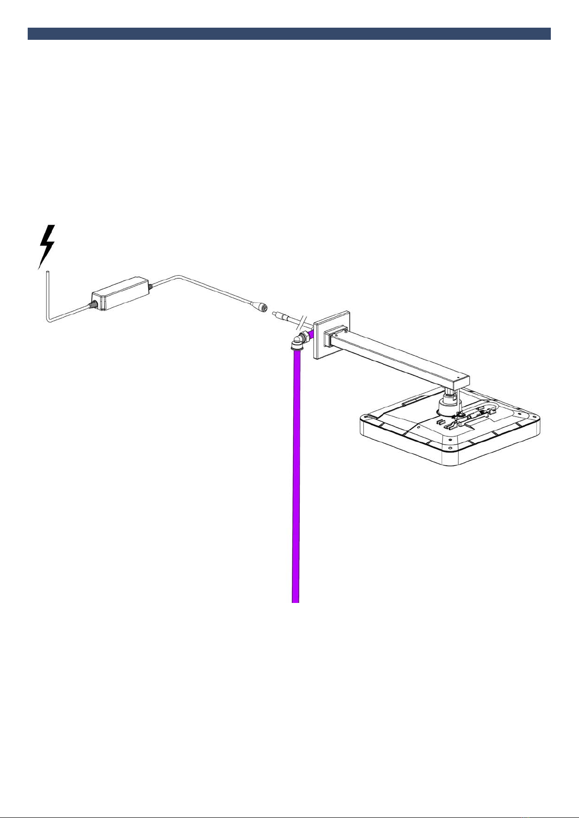
4. All plumbing connections must be completed before making
the electrical connections.
5.
a minimum at the valve output. If using a low pressure
(gravity fed) system a suitable pump will be required. Your
1.
local electrical supply company.
2.
mains system.
3.
circuits. This may be part of the consumer unit or a separate
unit.
4.
for maintenance or if not in use for extended periods. This
is a safety procedure recommended with all electrical
appliances.
5. Make sure all electrical connections are tight to prevent
overheating.
6. As with all electrical appliances, it is recommended to have
the shower and installation checked at least every two years
by a competent electrician to ensure there is no deterioration
due to age and usage.
Flashing Lights
To enhance the visual impact of the bubbles, this shower uses
1789-2015) and is safely above the 3-30Hz range (commonly
conditions).
ambient lighting and the environment in which it is installed (see
Anyone diagnosed with a condition which could be triggered by
3

System Diagram
10° Max tilt
of Ball Joint
Tilting of the BubbleSpa® Overhead Shower can be in any direction. All dimensions are in mm unless otherwise stated.
300
380
27+10
-8
118
300
46
78
105
1/2” BSP
10° Max tilt
of Ball Joint
300
380
27+10
-8
118
300
46
78
105
1/2” BSP
10° Max tilt
of Ball Joint
4

System Diagram
2
1
3
5
4
No. Part Qty
1 1
2 Water Path Connector 1
3 Wall Screws (Self Tapping 4.2 x 38mm) 4
4 Wall Plugs 4
5 1
5

System Diagram
10° Max tilt
of Ball Joint
*Drawing shows the lengths of the parts as supplied. The Inner Pipe can be cut down to an appropriate length if necessary.
The tilting of the BubbleSpa® Overhead Shower can be in any direction.All dimensions are in mm unless otherwise stated.
414
307 243
15
300
46
6

System Diagram
6
4
8
2
3
1
9
5
5
4
7
No. Part Qty
1 1
2 1
3Ceiling Arm Trim 1
4 Wall Screws (Self Tapping 4.2 x 38mm) 6
5 Wall Plugs 6
6Compression Nut 1
7Olive 1
8Mounting Plate 1
9 1
7

WallArm
Contents
2
Overhead Shower
Installation3
1
• x1 Wall Arm Assembly
• x1 Transformer
• x1 Water Path Connector
•
• x4 Wall Screws
• x4 Wall Plugs
•
8

Ceiling Arm
Contents
2
Overhead Shower
Installation3
1
• x1 Ceiling Arm Assembly
•
•
• x1 Transformer
• x1 Compression Nut
• x1 Olive
• x1 Mounting Plate
• x6 Screws
• x6 Wall plugs
•
Shower
9

Wall Arm Installation
10

Wall Arm Installation
the hole for the cable and outlet pipe is no bigger than 60mm
diameter.
12
3 4
Slide the WallArmTrim and Trim Sleeve to the wall. Plumbers’
in position.
that the Water Path Connector is no more than 10mm proud
of the wall tiles and is no more than 8mm inside the wall.Apply
plumber’s silicone grease onto the O-rings on the Water Path
Connector.
Feed the power cable of the Wall Arm Assembly into the wall and
supply. Then screw the Wall Arm Assembly to the wall using the
the Water Path Connector are not displaced.
O-rings
11

5 6
Wall Arm Installation
7 8
2 arrows on the connectors and then pushing the connectors
together until a click is heard. Then place the cables into the clips
on the Overhead Shower. Connect the other end of the power
cable to the Transformer. Then turn on the power supply to the
Overhead Shower from the mains.
Whilst the shower is running, check the entire installation for any
Overhead Shower. It is important that there is no water leaking as
12

• Always check for hidden pipes and cables before drilling.
•
9
10
Shower will light up. This is an indicator that power is being
supplied to the Overhead Shower. If you need to disconnect the
of the larger connector, then remove the small connector.
Wall Arm Installation
13

Ceiling Arm Installation
14

Ceiling Arm Installation
for the Wall Plugs on the ceiling of the shower cubicle.
1
Insert the Wall Plugs provided into the ceiling and screw the
Ceiling Arm Assembly using the screws provided.
2
Feed the power cable of the Ceiling Arm Assembly into the void.
Ceiling Arm Assembly will snap onto the bracket. The inner tube
supply. The inner tube may be cut to length if it is too long.
3
Plywood Sheet
Joists
Ceiling
It is recommended to use a sheet of plywood supported by joists
installing, make sure the inner pipe of the Ceiling Arm Assembly
is long enough to reach above the plywood sheet– cut the inner
pipe if it is too long. Once the position of the shower has been
determined, drill a hole that is bigger than 17mm but no larger
than 60mm diameter in the ceiling.
15

6
Ceiling Arm Installation
In the ceiling void, place the Mounting Plate over the inner tube.
Attach the Mounting Plate to the plywood with Wall Plugs and Wall
Screws provided. Then place the Olive and Compression Nut over
the inner tube and tighten the nut.
5
7 8
and slide on the CeilingArm Trim. The CeilingArm Trim should
stick to the tape. Silicone may be added on the back of the
Ceiling Arm Trim to help it stick.
Whilst the shower is running, check the entire installation for any
Overhead Shower. It is important that there is no water leaking as
16

109
Ceiling Arm Installation
Shower will light up. This is an indicator that power is being
supplied to the shower. If you need to disconnect the power cable,
connector then remove the small connector.
11
• Always check for hidden pipes and
cables before drilling.
•
pipes to clear debris from pipework
before connecting the Kelda
2 arrows on the connectors and then pushing the connectors
together until a click is heard. Then place the cables into the clips
on the Overhead Shower. Connect the other end of the power
cable to the Transformer. Then turn on the power supply to the
Overhead Shower from the mains.
17

standards, or the appropriate regulations in the country of installation.
~~
~~
3A Switched Fused Spur
(Supplied)
Overhead Shower
Connection
Waterproof DC
Connection
The BubbleSpa® Overhead Shower does not require its own [electrical port] on the RCB. Since the BubbleSpa® can be run from a port being used, eg.
a kitchen port or lighting. See next page for full details.
18

Output
1.05A
25.2W
Input
AC Current
Protection
Over Current 95-108%
Constant current limiting, recovers automatically after fault condition is
removed
Short Circuit Hiccup mode, recovers automatically after fault condition is removed
Over Temperature
Working Temp.
Max. Case Temp.
Working Humidity
Storage Temp. Humidity
Safety Standards
19

Low 1 2 3
Medium 1 2 3
High 1 2 3
Wet Mode
*Visual representation of how bubbles LOOK at dierent settings. Pressing the Button does not change the frequency of bubbles or ow rate of the BubbleSpa® shower.
is “1 Low” (see table below). The Overhead Shower will return to this setting in the event of the power being disconnected.
•
•
selected.
•
•
20
Other manuals for 95001000
1
This manual suits for next models
2
Table of contents
Other kelda Bathroom Fixture manuals
Popular Bathroom Fixture manuals by other brands

OPHARDT HYGIENE
OPHARDT HYGIENE SanTRAL Plus SMART UDU 5 M instruction manual

decina
decina SOFIA SHOWER PANEL installation instructions

Tassili Supra
Tassili Supra NEO-ROUND installation guide

Hans Grohe
Hans Grohe Pulsify 100 1jet EcoSmart 24320 Series Assembly instructions

PALAZZANI
PALAZZANI CROMOTERAPIA 995807 Assembly and maintenance instructions

ALT
ALT 1840 Series Installation & Care Guide