Important Safety Information
This product requires hot and cold water supply plus an
electrical connection (see “Electrical Installation” on page
11 for details). This product is not an electric shower.
Products manufactured by Kelda Showers are safe
and without risk provided they are installed, used and
maintained in good working order in accordance with
instructions and recommendations.
IMPORTANT! DO NOT operate the unit if the shower
head becomes damaged.
IMPORTANT! DO NOT restrict flow out of shower by
placing an obstruction in front of the shower head
nozzles.
GENERAL
1. Read all of these instructions and retain them for
later use.
2. DO NOT take risks with plumbing or electrical
equipment
3. Isolate electrical and water supplies before
proceeding with the installation.
4. The shower head must be cleaned regularly
with descalant to remove scale and debris.
The Air hoses must be cleaned periodically to
maintain performance and hygiene. PLEASE SEE
MAINTENANCE SECTION.
5. This product is not suitable for mounting into steam
rooms or steam cubicles.
6. The shower should not be installed in an outdoor
environment, including sheltered areas.
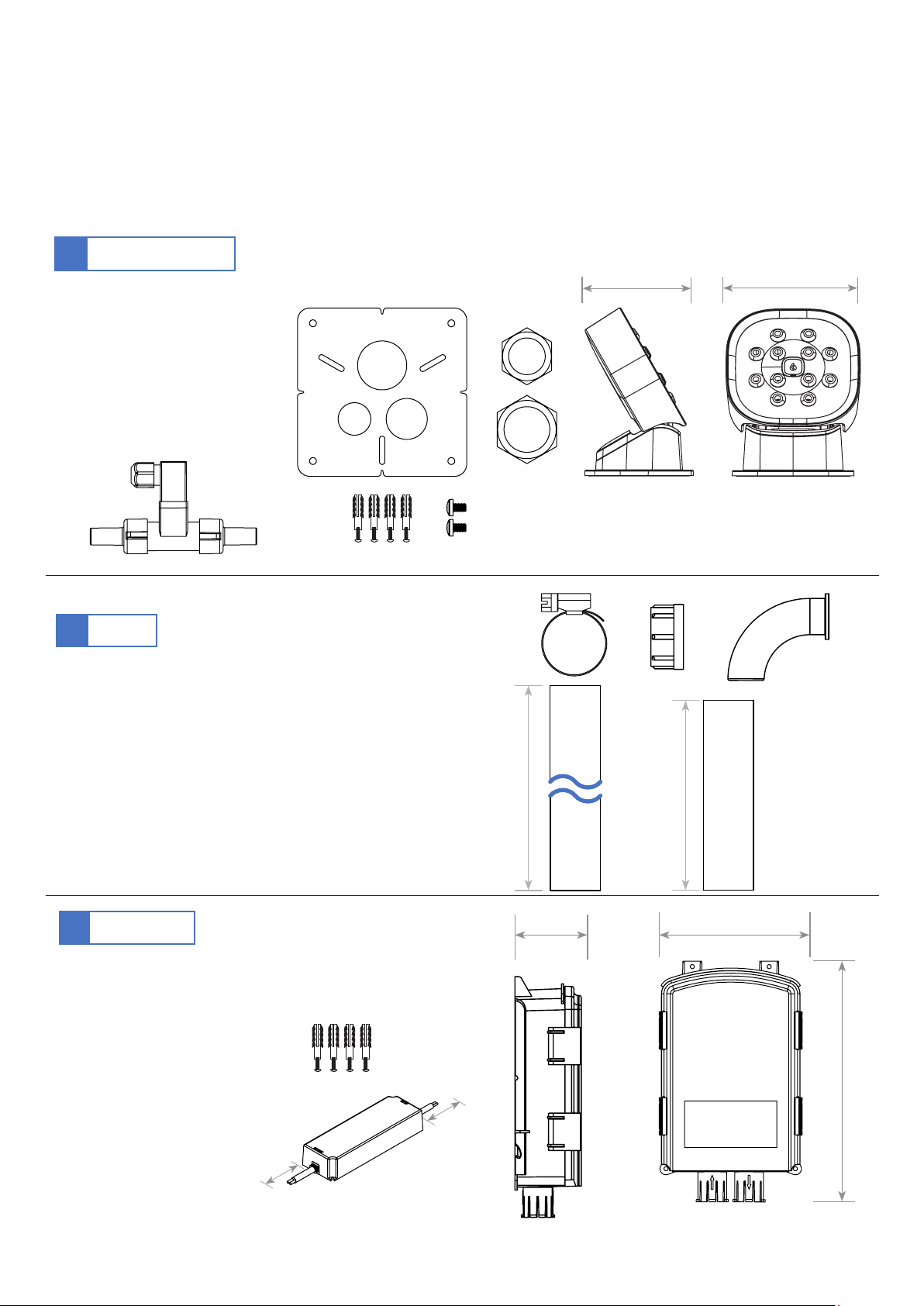
PLUMBING
1. The plumbing installation must comply with water
regulations, building regulations or any particular
regulations as specified by local water company or
water undertakers and should be in accordance with
BS EN 806 (Specifications for installations inside
buildings conveying water for human consumption.
Operation and maintenance).
2. IMPORTANT! The hot and cold water supply
pipes must be flushed to clear debris from before
connecting to water inlets on shower.
3. DO NOT solder pipes or fittings within 300mm of
the supplied hoses, as heat can transfer along the
pipework and damage components.
4. DO NOT use excessive force when making
connections to the flexible hose, solenoid or mixer.
5. All plumbing connections must be completed before
making the electrical connections.
6. Kelda products are designed to operate between
1 bar (0.1 MPa) and 5 bar (0.5 MPa). If you wish to
operate outside of this please discuss with a Kelda
Engineer.
ELECTRICAL
1. The installation must comply with BS 7671
‘Requirements for electrical installations’ (IET wiring
regulations), building regulations or any particular
regulations as specified by the local electrical supply
company.
2. In accordance with ‘The Plugs and Sockets etc.
(Safety) Regulations 1994’, this appliance is intended
to be permanently connected to the fixed wiring of
the electrical mains system.
3. Make sure all electrical connections are tight to
prevent overheating.
4. A 32A 30 mA Residual Current Circuit Breaker
Operator (RCBO) with over current protection MUST
be installed in all UK electric and pumped shower
circuits. This may be part of the consumer unit or a
separate unit.
5. Each shower must be connected to a 3A switched
fused spur which is easily accessible. Switch off
at fused spur for maintenance or if not in use
for extended periods. This is a safety procedure
recommended with all electrical appliances.
6. Make sure all electrical connections are tight to
prevent overheating.
7. As with all electrical appliances it is recommended
to have the shower and installation checked at least
every two years by a competent electrician to ensure
there is no deterioration due to age and usage.
3