Keller K2012 User manual

© Keller International, LLC. 1-800-578-8772 1
K2012 Traditional Barber Chair Assembly Directions
This is the K2012 Traditional Barber Chair from Keller International. This chair is
assembled by the purchaser which ma es it simple to disassemble whenever parts
need to be replaced.
NOTE: THESE DIRECTIONS SUPERCEDE
ANY FACTORY DIRECTIONS FOUND
INSIDE THE K2012 BARBER CHAIR
SHIPPING CONTAINER. USE THESE
DIRECTIONS TO ASSEMBLE YOUR K2012
TRADITIONAL BARBER CHAIR.

© Keller International, LLC. 1-800-578-8772 2
Factory Part # Part Name
34 & 40 & wood Armrest part 34, 40 plus wood arm complete assembly (each)
40 Armrest Cover (each)
9 Armrest Chromed Supports Left or Ri ht
38 and 36
Chair Back (
Cushion) New Style Sin le post. P
art
s 38 and 36
installed
21 Footrest Plate New style- Molded Rubber
21 Footrest Plate Old style - Cast Iron
22 Footrest – Cast Iron Rubber Cover
31 Footrest Pe Le
32 Footrest Pe Le HG4 Foot
14 Gas Piston
35 Headrest, CUSHION Only for Sin le Post
35,33 plus
Headrest, Complete with Sin le Post includes steel rod and
lockin (new style)
19,21,23,41 Le Rest Complete Assembly
19 Le Rest Chromed Side bars (each) ri ht or left
21 Footrest Plate - Molded Rubber or Cast Iron (with part 22)
23 Kick plate
41 Le Rest Pad
45 Reclinin Handle, Plastic
39 Seat Cushion
24 NG1-N Hydraulic Pump
25 NG1-N Foot Bail
27 660mm diameter Circle Plate

© Keller International, LLC. 1-800-578-8772 3
Remove All Parts from the Shipping Container
Assemble the Hydraulic Base - First
NOTE: DO NOT USE THE
BOLTS HOLDING THE PUMP
TO ITS SHIPPING BOARD.
Use the 4 – 8mm bolts & the 6mm
allen wrench to attach the pump to
the plate. Bolts should be tightened
until there is no gap between the
bolt heads & the plate bottom.
Foot
Pumper
BAIL

© Keller International, LLC. 1-800-578-8772 4
Attach the foot pumper bail as shown in the picture above.
NOTE: There is no longer a decorative rubber ring to mas the Pump to Plate
joint. The 3rd generation NG1-N Hydraulic pumps are now chromed all the way to
the bottom of the pump housing.
NOTE: If the foot pumper bail is attached to the wrong side – your hydraulic
pump will wor bac wards (pushing UP on the Bail will raise the barber chair
and pushing DOWN on the bail will loc the pump in that position).
NOTE: If you notice the foot pumper bail is attached to the wrong side – detach –
go 180º around to the other side of the pump and reattach properly.
Foot
Pumper
BAIL

© Keller International, LLC. 1-800-578-8772 5
Put the chair top onto the base and loc
it down with the M10 bolt provided
(tighten with a 17mm wrench). This
step is HEAVY. At least two people
should be available to perform this
operation.
Note: The chair pump brac et (or TOP
PLATE) is pre-bolted onto the bottom
of the chair and has a tapered hole & a
5-degree bac wards tilt.
This bolt
controls
the leg
rest and
footplate
tilt.
FRONT
OF
CHAIR
REAR
OF
CHAIR
Attach the Chair
to the Top of the
Hydraulic Base.

© Keller International, LLC. 1-800-578-8772 6
Front view of the padded
legrest / footrest assembly.
Tread Plate may be Molded Rubber
or Cast Iron with a Rubber Cover
M10 by 45mm

© Keller International, LLC. 1-800-578-8772 7
Install the padded legrest / footrest assembly onto the front of the
chair frame with the two M10 by 45mm Allen bolts.
NOTE: The chromed side legs go on the outside of the chair frame
tabs. Pass the 10mm bolts through the chromed legs and screw them
into the threaded holes on the chair frame tabs.
The foot
pegs are
adjustable.
The
foot
pegs
can be
lengthened
or shortened
to just miss
the floor.

© Keller International, LLC. 1-800-578-8772 8
Connect the joint lever flat bar
to the brac et on the bac side of
the footrest tread-plate.
NOTE: After assembly, pull the
reclining lever and recline the
chair enough to install the seat
cushion (the seat clip should
snap over the chair frame).
PLEASE SAVE THESE
DIRECTIONS.
Joint Lever Flat Bar
Brac et
Connect
Here

© Keller International, LLC. 1-800-578-8772 9
K2012 Seat Cushion Installation
Recline the chair a little to ma e it easier to install the seat cushion.
Place seat cushion on to the seat cushion metal frame – push cushion
bac towards the bac cushion and the “J” hoo should snap over
the seat cushion metal frame.
Remove the protective WHITE plastic sheet from the ic plate on
the front of the legrest / footrest assembly – to reveal the chrome.
All nuts and bolts should occasionally be chec ed to ma e sure they
are tight – especially the pump bolts underneath the circle plate.
Always leave your chair completely lowered at the end of each day.
NEVER pic the chair UP or MOVE it by the ARMS
unless the foot bail is PULLED UP and LOCKED.
Foot
Pumper
BAIL

© Keller International, LLC. 1-800-578-8772 10
PUMP OPERATING INSTRUCTIONS:
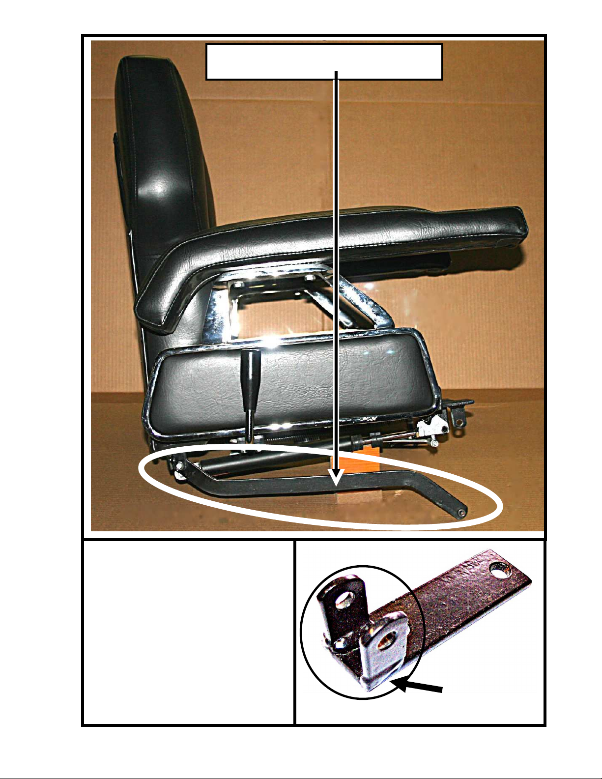
1. To raise the chair, pump the foot bail DOWN with short stro es until the chair reaches
the desired height. Pushing the foot bail to the bottom of your foot stro e will decrease
the amount of lift per stro e.
2. To lower the chair, push down the foot bail all the way DOWN and hold.
3. To loc the chair rotation, lift UP on the bail after reaching the desired height.
IMPORTANT PUMP MAINTENANCE:
All hydraulic pumps must have air removed from the pump before use.
Pump the chair all the way up and down (three times) with a person in the chair.
This will circulate the hydraulic fluid throughout the pump, eliminating the air.
The client must enter and leave the chair in the “ALL THE WAY DOWN” position.
Always leave the chair in the lowest position every night.
These steps must be performed due to tipping and movement of the base during shipping
and everyday use.
TROUBLE-SHOOTING GUIDE:
Q. Why does my chair go down very slowly with a person pumped up in the chair?
A. There may be air in the hydraulic oil - in the pump. See pump maintenance.
Q. Why does my chair rotate hard?
A. Hydraulic oil needs to wor its way into the bra e assembly. This should go
away after a wee or two.
A. The bra e is set at the factory and can be adjusted. Call Keller International for
directions.
Q. Why does the seat cushion move around / eep coming loose?
A. The seat clip under the cushion (on the bac edge) is bro en or bent. Call Keller
International for parts.
Q. Why does my chair bac recline by itself or drift bac wards?
A. Chair bac gas assist piston needs adjustment. Call Keller International for
directions.
Q. Why won’t my headrest stay UP?
A. The headrest needs adjustment. Call Keller International for directions.
NOTE: The vinyl should be cleaned with a general all-purpose household
cleaner and occasionally treated with a vinyl cleaner / conditioner

© Keller International, LLC. 1-800-578-8772 1
K2012 Economic Barber Chair
30 Minutes to Assemble
Five (5) Major Components
Instructions & Tools Included
Factory Safe Weight
Specification
400 to 450 pounds
Total Weight
Assembled
210 pounds

© Keller International, LLC. 1-800-578-8772 2
See more details on these bases at www.kellerinternational.com – on the parts page.

© Keller International, LLC. 1-800-578-8772 3

© Keller International, LLC. 1-800-578-8772 4
The headrest has an “infinite”
number of positions because of
the wedging rollers at the
bottom of the rectangular shaft.
Just pull UP on the headrest to
whatever height is desired and
let go – the headrest will stay in
that position until a lever is
lifted to lower the headrest.
The headrest can also be
completely removed from the
Barber Chair.
The maximum recline (see the
picture below) is around 50º to
facilitate shaving.
The footrest rises as the Barber
Chair is reclined.

© Keller International, LLC. 1-800-578-8772 1
K2012 Traditional Barber Chair Assembly Directions
This is the K2012 Traditional Barber Chair from Keller International. This chair is
assembled by the purchaser which ma es it simple to disassemble whenever parts
need to be replaced.
NOTE: THESE DIRECTIONS SUPERCEDE
ANY FACTORY DIRECTIONS FOUND
INSIDE THE K2012 BARBER CHAIR
SHIPPING CONTAINER. USE THESE
DIRECTIONS TO ASSEMBLE YOUR K2012
TRADITIONAL BARBER CHAIR.

© Keller International, LLC. 1-800-578-8772 2
Factory Part # Part Name
34 & 40 & wood Armrest part 34, 40 plus wood arm complete assembly (each)
40 Armrest Cover (each)
9 Armrest Chromed Supports Left or Ri ht
38 and 36
Chair Back (
Cushion) New Style Sin le post. P
art
s 38 and 36
installed
21 Footrest Plate New style- Molded Rubber
21 Footrest Plate Old style - Cast Iron
22 Footrest – Cast Iron Rubber Cover
31 Footrest Pe Le
32 Footrest Pe Le HG4 Foot
14 Gas Piston
35 Headrest, CUSHION Only for Sin le Post
35,33 plus
Headrest, Complete with Sin le Post includes steel rod and
lockin (new style)
19,21,23,41 Le Rest Complete Assembly
19 Le Rest Chromed Side bars (each) ri ht or left
21 Footrest Plate - Molded Rubber or Cast Iron (with part 22)
23 Kick plate
41 Le Rest Pad
45 Reclinin Handle, Plastic
39 Seat Cushion
24 NG1-N Hydraulic Pump
25 NG1-N Foot Bail
27 660mm diameter Circle Plate

© Keller International, LLC. 1-800-578-8772 3
Remove All Parts from the Shipping Container
Assemble the Hydraulic Base - First
NOTE: DO NOT USE THE
BOLTS HOLDING THE PUMP
TO ITS SHIPPING BOARD.
Use the 4 – 8mm bolts & the 6mm
allen wrench to attach the pump to
the plate. Bolts should be tightened
until there is no gap between the
bolt heads & the plate bottom.
Foot
Pumper
BAIL

© Keller International, LLC. 1-800-578-8772 4
Attach the foot pumper bail as shown in the picture above.
NOTE: There is no longer a decorative rubber ring to mas the Pump to Plate
joint. The 3rd generation NG1-N Hydraulic pumps are now chromed all the way to
the bottom of the pump housing.
NOTE: If the foot pumper bail is attached to the wrong side – your hydraulic
pump will wor bac wards (pushing UP on the Bail will raise the barber chair
and pushing DOWN on the bail will loc the pump in that position).
NOTE: If you notice the foot pumper bail is attached to the wrong side – detach –
go 180º around to the other side of the pump and reattach properly.
Foot
Pumper
BAIL

© Keller International, LLC. 1-800-578-8772 5
Put the chair top onto the base and loc
it down with the M10 bolt provided
(tighten with a 17mm wrench). This
step is HEAVY. At least two people
should be available to perform this
operation.
Note: The chair pump brac et (or TOP
PLATE) is pre-bolted onto the bottom
of the chair and has a tapered hole & a
5-degree bac wards tilt.
This bolt
controls
the leg
rest and
footplate
tilt.
FRONT
OF
CHAIR
REAR
OF
CHAIR
Attach the Chair
to the Top of the
Hydraulic Base.

© Keller International, LLC. 1-800-578-8772 6
Front view of the padded
legrest / footrest assembly.
Tread Plate may be Molded Rubber
or Cast Iron with a Rubber Cover
M10 by 45mm
Table of contents
Other Keller Indoor Furnishing manuals
Popular Indoor Furnishing manuals by other brands

Unfinished Furniture of Wilmington
Unfinished Furniture of Wilmington BD-2033A Assembly instructions

Songmics
Songmics OBG62 manual

RST
RST Milo OP-PECT4040-MILO Assembly instructions

VECELO
VECELO KHD-HD-NS14-BLK Assembly instructions

Jysk
Jysk HEBY 711-18-1011 manual

Habitat
Habitat Set of 2 Book Shelves 331/6636 Assembly instructions

Target
Target room essentials 249-05-0297 Assembly instructions

Systembuild Evolution
Systembuild Evolution 6777015COM manual

Alice's Home
Alice's Home CAHYA IRAWCHRX2 Assembly

PG BISON
PG BISON KINETIC FLATPAX Series Assembly guide

HOMCOM
HOMCOM 850-172 Assembly & instruction manual

Argos
Argos 906/4023 Assembly instructions